Appendix G
Standard Values of Resistors, Capacitors, and Inductors
G.1 Color Code of Resistors
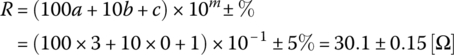
Except for wire‐wound/cermet/high‐power/precision resistors, most common resistors do not have their resistance value printed on them, but rather have a color code representing their resistance value as illustrated in Figure G.1. Table G.1 shows the numerical value or tolerance (manufacturer’s reliability rating) represented by each color. For example, the resistance value of a resistor with the four‐color band of yellow‐violet‐red‐silver is
and that of a resistor with the five‐color band of orange–black–white–gold–gold is
- (cf.) Visit the web site http://xtronics.com/kits/rcode.htm for more details about the color code.
G.2 Standard Values of Resistors
Discrete resistors are commercially available only in standard values depending on their tolerance as listed in Table G.2. Consequently, when the designed value of a resistor is 3.1 kΩ, we should use 30×102 ± 5%[Ω] or 309×101 ± 1%[Ω] unless we somehow have a resistor of 3.1 kΩ fabricated.
Figure G.1 Color code for resistors. (See insert for color representation of the figure.)
Table G.1 Color code of resistors.
| Color | Digit | Color | Digit | Color | Tolerance (%) |
| Black | 0 | Blue | 6 | Brown | 1 |
| Brown | 1 | Violet | 7 | Red | 2 |
| Red | 2 | Gray | 8 | Gold | 5 |
| Orange | 3 | White | 9 | Silver | 10 |
| Yellow | 4 | Gold | ‐1 (applied only to multiplier m) | None | 20 |
| Green | 5 | Silver | ‐2 (applied only to multiplier m) |
- (cf.) The commercially available resistors have the power (wattage) ratings of 1/8, 1/4, 1/2, 1, and 2W depending on their physical sizes.
- (cf.) Some resistors may exhibit parasitic effects of series inductance and parallel capacitance especially if the circuit containing them operates at very high frequency.
G.3 Standard Values of Capacitors
Discrete capacitors are commercially available only in standard values depending on their physical material/shape as listed in Tables G.3.1 and G.3.2. Table G.3.3 shows the letter tolerance code of capacitors. Most of them have their value (like 22 μF) printed on their body together with their breakdown voltage, while the capacitance value of ceramic condenser is printed as, say, 104, which means the capacity of
Table G.2 Standard values of resistors.
| 1% tolerance | 5% tolerance | 10% tolerance | 20% tolerance | |||||||||||||||
| 100 | 121 | 147 | 178 | 215 | 261 | 316 | 383 | 464 | 562 | 681 | 825 | 10 | 18 | 33 | 56 | 10 | 33 | 10 |
| 102 | 124 | 150 | 182 | 221 | 267 | 324 | 392 | 475 | 576 | 698 | 845 | 11 | 20 | 36 | 62 | 12 | 39 | 15 |
| 105 | 127 | 154 | 187 | 226 | 274 | 332 | 402 | 487 | 590 | 715 | 866 | 12 | 22 | 39 | 68 | 15 | 47 | 22 |
| 107 | 130 | 158 | 191 | 232 | 280 | 340 | 412 | 499 | 604 | 732 | 887 | 13 | 24 | 43 | 75 | 18 | 56 | 33 |
| 110 | 133 | 162 | 196 | 237 | 287 | 348 | 422 | 511 | 619 | 750 | 909 | 15 | 27 | 47 | 82 | 22 | 68 | 47 |
| 113 | 137 | 165 | 200 | 243 | 294 | 357 | 432 | 523 | 634 | 768 | 931 | 16 | 30 | 51 | 91 | 27 | 82 | 68 |
| 115 | 140 | 169 | 205 | 249 | 301 | 365 | 442 | 536 | 649 | 787 | 953 | |||||||
| 118 | 143 | 174 | 210 | 255 | 309 | 374 | 453 | 549 | 665 | 806 | 976 | |||||||
Table G.3.1 Standard values of electrolytic capacitors [μF].
| Maximum voltage 10 V | Maximum voltage 25 V | Maximum voltage 50 V | |||||||||
| 100 | 1000 | 10 000 | 10 | 100 | 1000 | 0.1 | 1.0 | 10 | 100 | 1000 | |
| 22 | 220 | 2200 | 22 | 220 | 2200 | 0.22 | 2.2 | 22 | 220 | 2200 | |
| 33 | 330 | 3300 | 33 | 330 | 3300 | 0.33 | 3.3 | 33 | 330 | ||
| 47 | 470 | 4700 | 47 | 470 | 4700 | 0.47 | 4.7 | 47 | 470 | ||
| 6800 | |||||||||||
Table G.3.2 Standard values of ceramic and mylar polyester capacitors.
| Ceramic disc capacitors [pF] with maximum voltage 200 V | Mylar polyester capacitors [μF] with maximum voltage 100 V | ||||||
| 10 | 100 | 1000 | 10 000 | 0.001 | 0.01 | 0.1 | 0.33 |
| 15 | 150 | 1500 | 15 000 | 0.0015 | 0.015 | 0.12 | 0.39 |
| 22 | 220 | 2200 | 0.0022 | 0.022 | 0.15 | 0.47 | |
| 33 | 330 | 3300 | 0.0033 | 0.033 | 0.18 | 0.56 | |
| 47 | 470 | 4700 | 0.0047 | 0.047 | 0.22 | 0.68 | |
| 68 | 680 | 6800 | 0.0068 | 0.068 | 0.27 | 0.82 | |
| 0.0082 | 0.082 | 1.0 | |||||
Table G.3.3 Letter tolerance code of capacitors.
| A | B | C | D | E | F | G | H | J | K | M | N | P | Z |
| +0.05 pF | +0.1 pF | +0.25 pF | +0.5 pF | +0.5% | +1% | +2% | +3% | +5% | +10% | +20% | +30% | +100% | +80% |
‐0.05 pF |
−0.1 pF | −0.25 pF | −0.5 pF | −0.5% | −1% | −2% | −3% | −5% | −10% | −20% | −30% | −0% | −20% |
If the tolerance is missing, it can be assumed to be ±20%. Note that electrolytic capacitors have positive/negative terminals with the positive one having longer leg, and if we are not careful to connect them in accord with the polarity they will leak or may be destroyed.
- (cf.) The commercially available capacitors have the working voltages of about 3∼1000 V.
- (cf.) Some capacitors may exhibit parasitic effects of parallel/series resistance and series inductance.
G.4 Standard Values of Inductors
Discrete inductors are commercially available only in standard values (with the tolerance of ±5%, ±10%, and ±20%) listed in Table G.4.
- (cf.) Most inductors exhibit parasitic effects of series resistance (due to the large number of turns) and parallel capacitance.
- (cf.) Visit the web site http://www.rfcafe.com/references/electrical/inductor‐values.htm for more details about the standard values of inductors.
For the desired values of the resistances, capacitances, and inductances, the standard values can easily be chosen from Tables G.2, G.3.1, G.3.2, and G.4 by using the following MATLAB routine ‘standard_value(val,RLC,glc,tol)’ where the input arguments are supposed to be given as follows:
- val: the desired value of a resistance, a capacitance, or an inductance;
- RLC: ‘R’, ‘C’, or ‘L’ for resistance, a capacitance, or an inductance;
- glc: ‘g’, ‘l’, or ‘c’ to look for the standard value slightly greater than, less than, or just close to the desired value; and
- tol: 1, 5, or 10 for 1%‐/5%‐/10%‐tolerance standard resistance value.
Table G.4 Standard values of inductors.
| 1.0 1.1 1.2 1.3 1.5 1.6 1.8 2.0 2.2 2.4 2.7 3.0 3.3 3.6 3.9 4.3 4.7 5.1 5.6 6.2 6.8 7.5 8.2 8.7 9.1 nH, μH |
| 1.0 1.1 1.2 1.3 1.5 1.6 1.8 2.0 2.2 2.4 2.7 3.0 3.3 3.6 3.9 4.3 4.7 5.1 5.6 6.2 6.8 7.5 8.2 8.7 9.1×10 nH, μH |
| 1.0 1.1 1.2 1.3 1.5 1.6 1.8 2.0 2.2 2.4 2.7 3.0 3.3 3.6 3.9 4.3 4.7 5.1 5.6 6.2 6.8 7.5 8.2 8.7 9.1×10²nH, μH |
| 1.0 1.1 1.2 1.3 1.5 1.6 1.8 2.0 2.2 2.4 2.7 3.0 3.3 3.6 3.9 4.3 4.7 5.1 5.6 6.2 6.8 7.5 8.2 8.7 9.1×10³nH, μH |
G.5 Standard Values of Zener Diode Voltage
| 2.4 2.5 2.7 2.8 3.0 3.3 3.6 3.9 4.3 4.7 5.1 5.6 6.0 6.2 6.8 7.5 8.2 8.7 9.1 |
| 10 11 12 13 14 15 16 17 18 19 20 22 |
| 24 25 27 28 30 33 36 39 43 47 51 56 60 62 68 75 82 87 91 |
| 100 110 120 130 140 150 160 170 180 190 200 |