5Secure Communication Technology Based on Chaos Synchronization
Chaotic system is sensitively dependent on the initial conditions, long-term unpredictability, and anti-interception capability. At the same time, chaotic system itself is deterministic, and it is completely determined by the equations, parameters, and initial conditions of the nonlinear system. Hence, it is easy to be produced and copied. The high randomness, unpredictability, high complexity, wide frequency band character, the deterministic parameters and initial conditions of the chaotic signal, and its easy implementation make it a hot topic in the research of chaos application.
When compared with modern communication, chaos communication has many advantages and differences. The similarities and differences between them are shown in Table 5.1 [18]. When compared with the traditional modern communication, the chaos communication has obvious advantages for its potential applications and development prospects. However, the chaotic secure communication technology, which is still in the early stages of development, needs to solve a series of key technical issues.
Chaotic secure communication is divided into chaos analogy communication and chaos digital communication. Chaos analog communication is usually achieved by nonlinear circuit systems, but it requires very high standards for electrical design and manufacture precision. In addition, it is difficult for synchronization implementation. Among the existing chaotic communication schemes, chaotic masking is used to transmit analog signals, and its disadvantage is that the fidelity and security of the scheme are still not satisfied. Chaotic digital communication has become a hot research topic because of its less dependence on the circuit element, easy implementation in hardware, convenience in computer processing, transmission with less loss of information, strong versatility, and wide application [112]. Chaotic digital communication mainly includes chaos shift keying (CSK), chaos spread spectrum, and chaos modulation.
5.1Chaotic Masking Communication
Chaotic masking is the simplest form of chaotic communication, where the information signal is superimposed on the chaotic signal directly and it is masked by the chaotic signal [113]. The principle block diagram is shown in Figure 5.1. Synchronization is achieved between the drive subsystem and the response subsystem. At the sender, message signal and chaotic signal with much larger amplitude are superposed to form a noise signal. The chaotic signal completely masks the useful information and realizes the secure communication. At the receiver, the response system is capable of reproducing the chaotic signal. If the received signal is subtracted by the chaotic signal generated by the response system, the message signal can be recovered correctly.
Table 5.1: Comparison between modern communication and chaotic communication.
| Content | Modern communication | Chaotic communication |
| History | Matured technology for over 100 years | Emerging information technology for over 20 years |
| Industrial base | Has become the core of the field of information technology | Research hot spot |
| Emission bandwidth | Information bandwidth and broadband emission | Broadband spectral emission |
| Relationship between theory and technology | Category obviously, system integrity (from information theory to communication technology, from communication software to circuit hardware, etc.) | Selection of new methods and new schemes to seek a breakthrough. Some approved communication schemes, such as circuit, laser, and computer network, have been proposed |
| Security technology foundation Key security technology | Mathematical methods, involving complex mathematical knowledge DES, IDEA, 3DES, RSA | Physical methods, involving chaos characteristics Chaos masking, chaos switching, chaos modulation |
| Confidentiality | Good performance, but there are loophole due to the period of the larger random number. It can be decoded, but it is very time-consuming, and high cost. | aperiodic, unpredictable, fast fading correlation function, and broadband characteristics. Stronger confidentiality |
| Robustness | Achieved certain robustness | Application of spatiotemporal chaos and hyperchaos can enhance the robustness. Difficult to be attacked |
| Capacity | Bulk can be achieved, but there are still restrictions | Dynamic storage capability with high capacity |
| Power | High | Low power and observational ability |
| Equipment cost The main safety issues of security system | High The fatal vulnerabilities of software, inefficient attack protection, and poor random number generator | Relatively low It is studying and is expected to address key issues, such as noise, channel distortion, and multichannel and multiuser problems |
Chaotic masking is realized by utilizing the chaos randomness and broadband power spectrum characteristics. Taking the low-dimensional chaotic synchronization signal as a modulation signal, the transmitted message is superposed on the chaotic signal. From the observation of power spectrum or chaotic time series, the transmitted message is not easy to be detected directly. To accurately extract the message signal, this method requires the sender and receiver chaotic circuit parameters to match exactly. That is, it requires the same initial state and the parameters. Synchronization will be failed for tiny difference. Therefore, it is very difficult for the attacker to analyze the key parameters. On the other hand, the parameters that match exactly put forward very high requirements to the design of the circuit.

Figure 5.1: Double-channel chaotic secure communication scheme based on drive–response synchronization.
At the sender, taking Lorenz chaotic system as an example, the mathematical model of the modulator is described as

where k is a compression ratio constant, which ensures that the useful signal m(t) is much less than the chaotic signal. x1 is the masking signal, and x2 is the synchronous driving signal.
At the receiver, the mathematical model of the demodulator is defined as

Obviously, as long as the synchronization between the response system and drive system is achieved completely, the useful information can be demodulated correctly. In order to save the channel resources, this scheme is improved, and the principle is shown in Figure 5.2. In this scheme, the driving signal consists of useful signal and chaotic signal, that is, the drive signal is the sum of the useful signal and chaotic signal, so only one channel is required to realize the secure communication. Here, taking Lorenz chaotic system as an example, the chaotic system equations for the sender and the receiver are given by, respectively,

Figure 5.2: Single-channel chaotic secure communication scheme based on drive–response synchronization.


In this scheme, the channel resource is saved. However, one of the obvious characteristics is that the drive signal is disturbed by the message signal, and synchronization cannot be accurately realized, which leads to the fact that the information signal cannot be fully recovered. Another notable feature is that the information signal doesn’t have any impact on the dynamic characteristics of the driving system, so the security of the secure communication system is not high enough, and it cannot effectively resist the third-party attack. To improve the security further, an improved scheme was proposed in Ref. [114] as shown in Figure 5.3. In this scheme, the sum of the information signal and the chaotic signal feedbacks to the drive system, so that the drive system and the response system have the same dynamic characteristics, so it can realize the complete synchronization, and the receiving signal can be demodulated completely. As the information signal is integrated into the chaotic system, it is more difficult for the attacker to obtain useful information from the channel. Here, taking Lorenz chaotic system as an example, the chaotic system equations for the sender and the receiver is written as, respectively,

Figure 5.3: Improved single-channel chaotic secure communication scheme based on drive–response synchronization.


To improve the secure performance of chaotic masking communication further, Carroll et al. [115] spread this improved chaotic masking scheme to the high-order-linked synchronization system, and its synchronization principle and secure communication scheme are shown in Figure 5.4. In this scheme, the receiver and the sender are composed of two cascaded chaotic systems. Taking Lorenz chaotic system as an example, the equations for the sender and the receiver are presented as, respectively,


Figure 5.4: Improved single-channel cascade chaotic secure communication based on drive–response synchronization.

5.2Chaos Shift Keying Communication
First, in 1993, Parlitz et al. [116] and Dedieu et al. [41] proposed the digital modulation method of CSK. Soon, Kolumban et al. [117, 118] successively put forward the improved CSK digital communication system, which mainly includes chaotic on–off keying (COOK), differential chaos shift keying (DCSK), frequency modulation differential chaos shift keying (FM-DCSK), quadrature chaos shift keying (QCSK) [119], and so on. Among these schemes, DCSK and FM-DCSK have better antinoise performance [120]. FM-DCSK was listed as a long-term research program by European Commission. In 2000, IEEE Transactions on CAS-I published the 12th special issue about chaos to discuss the performance of a class of digital modulation schemes. Compared with DCSK, QCSK has the same bandwidth and bit error rate (BER) performance, but the data transmission rate is higher. There are two demodulation methods, such as coherent demodulation and noncoherent demodulation.
CSK is a kind of chaotic modulation technology for transmitting digital information. The basic idea is to map the different information code of binary (or multinary) digital signal to the piecewise chaotic waveform. The modulated signal is detected in the receiver based on the correlation reception theory. It needs a chaotic basis function or multiple chaotic basis functions for CSK modulation. A basis function of CSK has two types at least, such as COOK and CSK. The antinoise performance of bipolar coherent demodulation of CSK is better than that of COOK. If the bit energy remains constant and the chaotic basis function is recovered accurately at the receiver, the antinoise performance of the CSK is equivalent to that of Binary Phase Shift Keying (BPSK). The noncoherent detection cannot detect the bipolar CSK, and the antinoise performance of the noncoherent COOK is worse than that of the coherent COOK, but the COOK can achieve the best antinoise performance when the bit energy keeps constant. The decision threshold of the demodulation of reverse-phase CSK and COOK depends on the signal-to-noise ratio (SNR). When two basis functions are adopted, this problem can be solved. When symbols “0” and “1” are mapped to two different chaotic waveforms, the CSK of the two basis functions is formed, and the antinoise performance of coherent demodulation is better than that of the noncoherent demodulation. Especially, through choice of orthonormal basis functions, the decision threshold level becomes zero, and the performance has nothing to do with the SNR, and its performance is similar with that of coherent Frequency Shift Keying (FSK).
5.2.1COOK Communication
COOK is the most simple CSK communication, and the structure of basic principle is shown in Figure 5.5. {bi} is a binary information signal with “1” and “–1.” When bi = 1, the switch is turned on. When bi = –1, the switch is turned off. At the receiver, the information signal is recovered by employing the correlation algorithm. If the input signal is of equal probability distribution, and the average bit energy for a single symbol to E b, then the code energies of “1” and “–1” are 2Eb and 0, respectively. Obviously, the larger the bit energy gap, the better the antinoise performance of the signal. The structure of this scheme is simple. For example, it only needs a chaotic oscillator, but the security of the system is not high.

Figure 5.5: System principle block diagram of noncoherent COOK modulation/demodulation.
5.2.2CSK Communication
Next, we introduce the principle of CSK communication based on two chaotic signal generators. The structure of the transmitter is shown in Figure 5.6. {bi} is a binary sequence of information signal, which only includes “1” and “–1”. After modulated by the modulator, the signal transmitted in the channel is a noise-like chaotic signal, whose mathematical description is
In the receiver, coherent or noncoherent mode is used to recover the information signal, and the principle of coherent demodulation is shown in Figure 5.7. The output of the correlator is
Obviously, if bi = 1, then si(t) = g1(t), ri(t) = g1(t) + n(t). We obtain zi1 > zi2, and the recovered signal is bi = 1. If bi = –1, then si(t) = g2(t), ri(t) = g2(t) + n(t). We have zi1 < zi2, and the recovered signal is bi = –1.

Figure 5.6: Block diagram of CSK modulator.


By using the noncoherent demodulation, the demodulation principle is shown in Figure 5.8, and the output of the correlator is
For the CSK noncoherent demodulation, the receiver need not recover the chaotic carrier, and the detector is based on the bit energy of the transmission signal. If the decision threshold is set to the median of the two bit energies, then the received signal can be demodulated correctly. Obviously, the selection of the optimal threshold is closely related to the SNR of the system. So the threshold shift is the main defect of the noncoherent demodulation.
Next, we take CSK digital secure communication system based on the unified chaotic system as an example to illustrate, and the system structure is shown in Figure 5.9. The chaotic systems of the transmitter and receiver are unified chaotic system. The chaotic system 11 in the transmitting end and the chaotic system 21 in the receiving end have the same parameter α1, and the chaotic signal generated by them are x11(t) and x21(t), respectively. The chaotic system 12 in the transmitting end and the chaotic system 22 in the receiving end have the same parameter α2, and the chaotic signals generated by them are x12(t) and x22(t), respectively. By employing the synchronization strategy, the unified chaotic systems 11 and 12 at the sending end are synchronized with the unified chaotic systems 21 and 22 at the receiving end, respectively, then we have x11(t) = x21(t), x12(t) = x22(t). The binary digital signal a(t) = {an} is used to control the chaotic signal. When a(t) is of high voltage, x11(t) is sent. When a(t) is of low voltage, x12(t) is sent. The transmitted signal in the channel is expressed as
Obviously, the signal transmitted in the channel is chaotic. If the noise in the channel is Gaussian white noise n(t), then the signal at the receiving end is expressed as

Figure 5.9: Principle block diagram of CSK digital secure communication system based on unified chaotic system.
For bipolar CSK, due to the correlation integral, two signal energies cannot be distinguished, so we can only use coherent demodulation method to demodulate the signal.
The chaotic signals are broadband nonperiodic signals, so the chaotic signals obtained by the same chaotic system with different initial conditions or generated by the same system with different system parameters are almost orthogonal. The correlation properties of chaotic signals are similar to those of Gauss white noise. Generally, the cross-correlation of the chaotic signal approximates to zero, and the autocorrelation approximates to the impulse function. The correlation properties of chaotic signals generated by the unified chaotic system are shown in Figure 5.10.
The receiver is composed of a chaotic synchronization system, a correlator (including multiplier and integrator), and a sampling decision device. If the outputs of correlator 1 and correlator 2 are z1 and z2, respectively, and their outputs are

Figure 5.10: Correlation characteristic of chaotic signals generated by the unified chaotic system: (a) autocorrelation and (b) cross-correlation.
where ρ = x11(t)x12(t)dt/Eb is the correlation coefficient of chaotic signals. When T the two signals are completely orthogonal, ρ = 0![]() is the bit energy of the chaotic signal. Obviously, if the correlator output signals, z1 and z2, are sampled to be decided, then the original signals can be recovered by the decision rules
is the bit energy of the chaotic signal. Obviously, if the correlator output signals, z1 and z2, are sampled to be decided, then the original signals can be recovered by the decision rules
Obviously, ignoring the effect of noise, the noise tolerance of coherent demodulation in the receiver system is Nc = (1 – ρ)Eb. The output signal of the decision device is b(t). It can be seen that the demodulation performance of the system is related to the characteristics of the chaotic signal. Because the autocorrelation of the chaotic signal generated by the unified chaotic system with different parameters is close to δ(t), and its cross-correlation is very weak, the system has a good correlation demodulation performance and the original signal can be recovered, that is b(t) = a(t).
Next, we discuss the BER performance and security performance of CSK secure communication based on unified chaotic system. Let the two possible deterministic signals arriving at the receiver be x1(t) and x2(t), respectively, and their durations are (0, T), and have the same energy Eb. The noise n(t) at the input of the receiver is Gauss white noise with zero mean, and its unilateral power spectral density is n0. According to the principle of the best reception, in the case of equal priori probabilities, the limit BER performance is

where erf(x) is the error function, and ρ is the cross-correlation coefficient between signals x1(t) and x2(t), and its range is (–1, 1). Because x1(t) and x2(t) are orthogonal signals, the cross-correlation coefficient is zero. The BER performance of the system is rewritten as

The BER simulation result of the CSK system is shown in Figure 5.11. When the SNR is greater than 10 dB, the BER is less than 10–6.

Figure 5.11: BER performance of the CSK system.
The security of CSK communication system is good, and it is mainly manifested in the following aspects. First, the system has strong anticrack ability, because the signal transmitted in channel is chaotic. With the evolution of the chaotic system, different chaotic signals represent the same two value signals. It is equal to “one time pad,” so it is unbreakable. From the view of cryptography, the system has a huge key space. The chaotic system is sensitively dependent on initial conditions. The unified chaotic systems with different parameters and different initial conditions can produce different chaotic signals, so chaotic system parameters and initial value can be used as keys. Different chaotic dynamical equations can produce different chaotic signals, and different chaotic variables also can be modulated. In addition, different synchronous mode also affects the demodulated signal. So the key space of the system is composed of parameters, initial values, chaotic systems, chaotic variables, and synchronization modes. The larger the key space is, the higher the security performance is.
It is worth noting that the good anti-interference and security of the system is at the cost of the complexity of the system. In practice, we should consider the trade-off between these two aspects. Because chaotic signal is nonperiodic, the bit energy of output information signal is not entirely consistent. Even in the noise-free case, there is also a deviation for the results related to the estimation, so it will affect the BER performance of the system. To solve this problem, we can use the frequency modulation (FM) to modulate CSK, namely FM-DCSK modulation.
According to the principle shown in Figure 5.9, the simulation model is obtained as shown in Figure 5.12. If the parameter α = 1 for the chaotic system 11 and the chaotic system 21, then initial values are (–5, –5, –5). At the same time, if the parameter α = 0.3 for the chaotic system 12 and the chaotic system 22, then initial values are (10, 10, 10). The chaotic variable x is modulated by the information signal a(t). When a(t) = 1, the modulated signal s(t) transmitted in the channel is the chaotic signal x11 generated by the unified system 11. When a(t) = 0, the modulated signal s(t) transmitted in the channel is the chaotic signal x12 generated by the unified system 12. By using the chaos synchronization control strategy, the synchronization between the unified chaotic systems is achieved as shown in Figure 5.13. Bernoulli random binary sequence is used as the information source. The integrator is triggered by the rising edge of external clock pulse. The sampling–holder is triggered by the falling edge of external clock. Decision is realized by the relevant logic comparator. The simulation results are shown in Figure 5.14, where T(t) is the system clock signal; a(t) is the modulation signal; s(t) is the modulated signal transmitted in channel; and b(t) is the recovered information signal at the receiver. Obviously, b(t) = a(t), that is, chaos signal demodulates correctly. Simulation results show that the original binary digital signal can be demodulated in this CSK secure communication scheme correctly.


Figure 5.13: Synchronization phase diagram of the variables between the sender and receiver: (a) x11(t)–x21(t) and (b) x11(t)–x22(t).
5.2.3DCSK Communication
In 1996, Kolumban et al. [117] proposed the DCSK scheme, and it solved the problem of CSK decision threshold value depending on the SNR. The basic principle is that each digital symbol is represented by two chaotic segments signal. The first segment is called “reference signal,” and the second segment is named “useful signal.” When we send “1,” two same segments are sent (same phase). When we send “0,” the two inverse phase segments are sent (inverse phase). In the receiver, the correlation of these two segments is calculated, and the information signal is recovered according to the correlation value. When the output of the correlator is more than 1, the output signal is “1.” When the output of the correlator is less than 1, the output signal is “0.” The principle of DCSK modulator is shown in Figure 5.15.


From Figure 5.15, the signal transmitted in channel is presented as
Because each bit is mapped to two continuous segments with the length T/2, the information signal at the receiver can be recovered by coherent demodulation. The demodulation principle of the DCSK scheme is shown in Figure 5.16. In this demodulation scheme, the output signal of the correlator is

Compared with CSK and COOK, the advantage of the DCSK scheme is that the decision threshold is zero whether there is noise or not. The reference signal and carrying information signal go through the same channel, so it is not sensitive to channel distortion, and it has a good antinoise performance. The shortage of DCSK is that it can only be used in the chaotic digital communication with low bit rate. To solve this problem, in 1998, Kolumban et al. proposed a DCSK scheme based on FM-DCSK [118].
5.2.4FM-DCSK Communication
FM-DCSK is constituted by DCSK and a frequency modulator. The output of FM is a chaotic signal with band-limited and uniform power spectrum density. The structure of FM-DCSK modulator is shown in Figure 5.17. It employs the chaotic analog phase-locked loop (APLL) to generate band-pass chaotic signal, and then FM is applied for chaotic signals. The subsequent parts are consistent with DCSK, which transmitsreference signal in [0, T/2] and transmits same phase chaotic FM signal or inverse phase chaotic FM signal in [T/2, T].

Figure 5.17: Principle block diagram of FM-DCSK modulation.
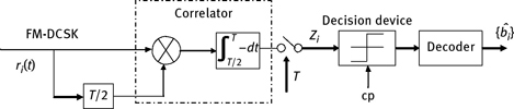
The demodulation principle of the FM-DCSK is shown in Figure 5.18. Similarly with that of DCSK, it employs the correlation receiving principle to demodulate the received information {bi}. For noise channel, the output of the FM-DCSK correlator has zero variance. Its data rate is not limited by the characteristics of the chaotic signal, and its decision threshold is identically zero. Thus, FM-DCSK can improve the symbol rate and reduce errors. When APLL is designed correctly, we can obtain the chaotic band-limited signal with uniform power density, which makes the output (bit energy) of the receiver is constant, regardless of the data rate. Thus, FM-DCSK has higher data rates, and its antinoise performance is the same with that of DCSK.
When compared with other chaotic modulation schemes, FM-DCSK and DCSK have better robustness to multipath interference and nonideal channel. FM-DCSK modulation is suitable for wireless local area networks, indoor wireless communications, mobile communications, and others which are sensitive to multipath interference.
5.2.5QCSK Communication
QCSK is a kind of chaotic communication scheme, which is similar to the conventional quadrature phase modulation. When compared with DCSK, it has the same bandwidth, approximate BER characteristics, but higher data transmission rate. The basic principle of QCSK is to generate the orthogonal chaotic signal at the specified time interval. In QCSK, the linear combination of two chaotic basis functions is usedfor coding four symbols. QCSK can be regarded as a combination of two DCSK systems. A double data rate is obtained by increasing complexity of the QCSK.
To explain the principle of QCSK, first, the concept of orthogonal chaotic signal is presented. If two independent chaotic signals c1(t) and c2(t) (or even different segments of the same chaotic signal) exhibit very low cross-correlation, they are orthogonal in a time interval [0, τ], namely
If x(t) is a chaotic reference signal defined in the interval t ∈ [0, τ], and it has a zero mean. In the interval t ∈ [0, τ], x(t) can be expanded as follows by Fourier series (A0 = 0):
where ω = 2π/τ. Correspondingly, the average power of x(t) in the interval t ∈ [0, τ] is
The orthogonal signal y(t), in the interval t ∈[0, τ], can be obtained by each Fourier frequency component of x(t) with the phase shift π/2, namely
Then the signals x(t) and y(t) are orthogonal over the interval t ∈ [0, τ] and their power is equal, i.e.

The above properties are equivalent to
According to definition formula (5.26) of the reference quadrature signal y(t), the x(t) and y(t) are extended into the periodic signal with the periodic τ. It is found that y(t)is the Hilbert transform of x(t), and the Hilbert transform of the given signal can be calculated by the following methods:
- Frequency domain method: It is basically the same as the method of generating Hilbert transform in Amplitude Modulation - Single Side Band modulation. A fast Fourier transform (FFT) is applied to a chaotic sequence with length k, and then remove the negative frequency (signal energy) corresponding to FFT coefficients. It is obtained by inverse FFT transformation. At present, the algorithm can be realized by a special digital signal processing (DSP) chip.
- Time domain method: It is achieved by the design of digital Hilbert converter with finite impulse response (FIR) or infinite impulse response (IIR). A simple method for calculating the Hilbert transformation of a given discrete signal is to design an FIR filter which is approximated by Hilbert transform. The FIR filter can be implemented by the ideal impulse response with appropriate width:
In the interval I = [0, τ], a chaotic sampling orthogonal base function is defined as
where E4 = Pxτ is the energy of x or y over the interval I. So we have
The orthogonal condition (5.32) indicates that the energy of cx and cy is constant at each interval I. The constant is one in special case. The chaotic signal can be represented by a linear combination of cx and cy, namely ms(t) = ascx(t) + bscy(t), where s represents a signal space symbol. Equivalently, the symbol s can be expressed in plural form, namely, ![]()
Being similar to DCSK and QCSK, the modulator structure is shown in Figure 5.19. It includes a chaotic generator, which generates the signal cx at each interval [0, T/2], and the corresponding quadrature signal cy is generated by the filter. For simplicity, it is assumed that the system has no time delay. According to the symbol s, the encoder generates a linear combination of cx and cy. Information symbol is provided by a bit/symbol converter, and the converter maps each pair of information bits into a symbol. Thus, each symbol period transmits 2 bits information. Then, the QCSK signal is formed by the two-channel analog multiplexer with the switching time T/2. Note that although there is no filter in the figure, the QCSK scheme must contain a low-pass band-limiting filter to limit the bandwidth of transmission signal. The chaotic reference signal segment r(t) = Ebcx(t) is transmitted in the first half symbol period of the transmission symbol s, and the information segment i(t) = Ebms(t) is transmitted in the second half of the symbol period, where s represents the symbol that needs to be transmitted, while Eb represents the energy per bit. The orthogonal condition (5.32) shows that the energy per transmitted bit is a constant. If the symbol period is T = 24, then the QCSK signal is

Figure 5.19: Principle block diagram of QCSK modulator.
where s = 0, 1, 2, 3.
The simplified block diagram of QCSK demodulator is shown in Figure 5.20. QCSK signal may be demodulated by the method of differential coherent detection. During the process of demodulation, the symbol period is assumed to be synchronized. That is, the beginning of each symbol is taken as the starting of the coherent process at the receiver.

Figure 5.20: Principle block diagram of QCSK demodulation.
In theory, by using the chaos basis signals cx and cy, carrier information segment i(t) = Ebms(t) is processed in the interval [T/2, T], and we can recover the plural ms = as+jbs. In fact, according to formulas (5.27) and (5.28), we can obtain
At the receiver, we can observe noise, filtered reference signal r(t), and information segment i(t). If the signal is only affected by the additive Gaussian white noise, then the input of the correlator A in Figure 5.20 is
The estimated value of the quadrature signal H[r̃] is generated by the disturbed chaotic reference signal, where H is the Hilbert transform operator:
where n′(t) = H [n(t)]. With the ideal Hilbert transform, the statistical properties of n′(t) are the same as that of n(t).
Considering the orthogonality of cx and cy, the output of the correlator is


CSK belongs to chaotic digital secure communication. When the basis function is strictly recovered, the noise performance of the coherent reception is better than that of the noncoherent reception. If the orthogonal basis function is chosen, the chaotic keying and the traditional digital modulation can achieve similar noise performance. However, at present, it is difficult to meet the requirements of the strict recovery basis function, and it is more difficult to regenerate the chaotic basis function than to regenerate the periodic basis function. As a result, the performance of the coherent chaotic keying communication is slightly less than that of the same kind of traditional digital communication. But CSK belongs to broadband communication, and the performance of chaos communication shows more superiority in multipath communication environment. Among CSK communication schemes, QCSK and FM-DCSK have better performance and application prospect.
5.3Chaos Parameter Modulation
Chaos parameter modulation is also known as wide spectrum transmission. The basic idea is that an information signal is injected into the transmitter, and thus it changes the dynamic characteristics of the original chaotic system. So the information signal is modulated. Compared with CSK and chaotic masking, chaos parameter modulation has the following advantages. First, it employs the whole range of the chaotic signal spectrum to hide information. Second, it increases the sensitivity to parameter variation, thereby enhancing confidentiality.
For CSK technology, no matter when the value of binary information signal changed, there is always a synchronization waiting time because of the difference of both initial conditions. While for chaos parameter modulation, receiver tracks transmitter continuously, and two chaotic system states would surely be the same. Compared with chaotic shift keying, it is expected to get a higher bit rate. In addition, with further development of chaos modulation technology, the direct chaotic spectrum expansion technique is also used as a chaos modulation technique.
Research results show that the main drawback of chaos communication scheme is being susceptible to channel noise and distortion. The traditional masking communication requirements of the power information signal are far lower than that of chaotic signal, which makes chaotic masking communication more difficult to be used in practice. A new method of chaotic pulse position modulation (CPPM) is proposed in Ref. [121], which shows good performance in the case of channel distortion. This scheme is based on the chaotic pulse sequence, and the interval between the pulses is determined by the chaotic characteristics of the nonlinear function. The pulse sequence of chaotic pulse interval modulation is used as a carrier. Binary information is modulated onto a carrier by pulse position modulation (PPM). As a result, each pulse is unchanged or delayed some time depending on the transmission information “0” or “1.” The pulse duration of “0” or “1” is estimated by chaotic pulse sequence synchronization at the receiver, and thus the transmission information is demodulated in this way.
The block diagram of chaotic pulse position modulator is shown in Figure 5.21. The chaotic pulse signal generated by chaotic pulse generator is expressed as

Figure 5.21: Principle block diagram of chaotic pulse position modulator.
where W(t – tj) represents a pulse waveform generated at time tj, and tj is expressed as
where Tn is the time interval between the nth pulse and the (n–1)th pulse. The time interval sequence Ti represents the iteration of the chaotic process. For the design convenience, we consider the chaos is generated by a one-dimensional map Tn = F (Tn–1), where F (⋅) is a nonlinear function.
The information is encoded in the chaotic pulse signal by adding the delay time in the pulse interval Tn. Thus, the resulting pulse sequence can be defined as
where Sn is the information signal. Only binary information is considered here, so Sn is equal to 0 or 1. m represents the modulation degree, and the parameter d is the time delay constant for the modulation and demodulation. When we design chaotic pulse generator, the choice of the nonlinear function F (⋅), and parameters d and m should ensure the chaotic performance of the map.
The transmission signal is a CPPM signal in the channel, which is denoted by

where Tn is generated by formula (5.43), and we assume that the duration of each pulse W(t) of the pulse sequence is much less than the minimum value of the pulse interval Tn. When detecting information at the receiver, the demodulator is triggered by receiving pulse U(t). After measuring successive time intervals Tn and Tn–1, the information signal is recovered as
If the nonlinear function F (⋅), parameters d and m at the receiver are same with those of the sender, then the encrypted information Sn can be easily recovered. When the matching accuracy of nonlinear functions is not sufficient, large decoding error occurs.
The demodulator principle is shown in Figure 5.22. When the demodulator is synchronized with the pulse modulator, to detect a single bit of the transmission information, the demodulator must simply determine whether the desired position of the transmitted pulse is delayed. In the figure, the integrator, sample and hold circuit, and a nonlinear threshold function module are reset or triggered by the pulse from the transmitter, not by the feedback loop within the receiver. To be exact, only when the input signal U(t) from the input channel exceeds the threshold, they are triggered. For each received pulse, the result of V(tn+1) – F(vn) is calculated and used to determine whether the pulse is delayed. Assuming that the difference is less than the reference value β(d + m/2), the data bit Sn+1 is determined to be “1,” otherwise, it is determined to be “0.”
Another important part of the receiver is the window selection module. Once the receiver has correctly received two consecutive pulses, the receiver can predict the fastest time to receive the next pulse. It means that the input of the demodulator can be masked at this time, which is done by the window selection module. In the experiment circuit, the input of the receiver is opened by a window control pulse generated by the comparator at the moment ![]() and the input end is turned on until the demodulator is triggered by the first received pulse. So the window selection module greatly reduces the probability of the receiver triggered by the noise, interference, or the pulse of other users.
and the input end is turned on until the demodulator is triggered by the first received pulse. So the window selection module greatly reduces the probability of the receiver triggered by the noise, interference, or the pulse of other users.

Figure 5.22: Principle block diagram of the chaotic pulse position demodulator.
Although the performance of CPPM is slightly worse than that of BPSK, noncoherent FSK, and ideal PPM, it has the following characteristics:
- Low probability intercept and low probability decoding ability.
- Although the complexity of the circuit is increased slightly, the security of communication system is improved.
- Compared with the majority of the communication schemes based on chaotic transformation, the system presents very good performance.
- CPPM can be used for multiuser communication.
- Compared with other pulse system, it eliminates any traces of periodicity of the transmission signal spectrum due to its independent period clock.
5.4Chaotic Spread Spectrum Communication
Chaotic spread spectrum communication is divided into direct sequence spread spectrum (DS/SS) and frequency hopping spread spectrum (FH/SS). The principle is to use the chaotic sequence as the pseudorandom sequence. Common pseudorandom sequences include msequence, Gold sequence, and Bent function sequence, but these sequences have a certain periodicity, limit numbers, and poor anti-interception ability. Chaotic sequences are nonperiodic sequences, which have the statistical properties of approaching Gauss white noise. The chaotic sequences generated by different systems or with different phases are different sequences.
5.4.1Principle of Chaotic DS/SS Communication
A chaotic DS/SS communication system is built instead of pseudorandom codes with the chaotic sequences [122], and its principle diagram is shown in Figure 5.23.
Here, assume each user is synchronized, spread spectrum codes are synchronized, and the signal power of each user is same. If there are M users working at the same time totally, and the message data of each user is ai(k) (i = 1,2,. . . ,M), the original data signal of the ith user is expressed as
where di(n) is the information bit value of the ith user, di(n) ∈ { – 1, 1}. Let xi(n) be the chaotic spread spectrum sequence of the sender of the ith user, and its expression is![]() where gi(n) is the spread spectrum characteristic sequence of
where gi(n) is the spread spectrum characteristic sequence of

Figure 5.23: Principle block diagram of multiuser chaotic sequence spread spectrum communication system. the ith user.
The input signal r(n) of the receiver is expressed as
where Ai(n) is the carrier signal amplitude of the ith user. N (n) is the zero mean Gauss white noise. So, the output of the correlator of the receiver of the ith user is
where ![]() is the chaotic spread spectrum sequence of the receiver of the ith user, and the system synchronizes between the sender and the receiver, that is,
is the chaotic spread spectrum sequence of the receiver of the ith user, and the system synchronizes between the sender and the receiver, that is, ![]() Let Tb be the time width of each original information bit, then
Let Tb be the time width of each original information bit, then

For formula (5.49), the first item is the desired information component. The second item is the recovery data obtained by the received signal with the kth signal itself, and multiple access interference (MAI) caused by other users. Obviously, the MAI term is related to the user number k, the amplitude of the signal of other user, and the cross-correlation coefficient ρi,k, where ![]() The third item is noise interference.
The third item is noise interference.
After the integral (correlation operation) of the receiver for the ith user, the signal is decided by the decision threshold, which is zero. The data is demodulated by the ith user at the receiver according to
To sum up, whether the user information is correctly recovered is greatly related with the characteristics of the spread spectrum code.
5.4.2Generation of Chaotic Spread Spectrum Code
Taking three typical chaotic maps, including logistic, Chebyshev, and Tent map as examples, the binary chaotic spread spectrum sequence is generated [123]. In the multiuser chaotic sequence spread spectrum communication system, spread spectrum sequence is a binary sequence with value ±1, namely, the real values of chaotic map sequences are quantized into binary to generate spread spectrum sequence.
5.4.2.1Logistic Chaotic Map
Logistic map equation is
where r is the system parameter, and r ∈ (0, 4]. When 3.5699 . . . < r ≤ 4, the system is chaotic. The mean value of the sequence is 0.5.
5.4.2.2Chebyshev Chaotic Map
The ω-order Chebyshev chaotic map is defined as
where ω is usually taken as an integer power of 2, and the mean value of the sequence is 0.
5.4.2.3Tent Chaotic Map
The Tent chaotic map is defined as
where 0 < a < 1, and the mean value of the sequence is 0.5.
Next, we discuss the balance and correlation of the three kinds of chaotic sequences.
5.4.2.3.1 Balance of the Sequences
The balance of a sequence is determined by the statistical distribution about “1” and “–1” in the sequence. If P and Q denote the number of “1” and “–1” in the chaotic sequence, respectively, then the balance degree of the sequence E is defined as
where N is the total number of symbol sequence. The sequence balance is related with the carrier suppression degree of the DS/SS system. The imbalance of spread spectrum sequence will lead the leakage of carrier information, or be prone to error or lost. Thus, it is important to study the balance of the direct spread spectrum system (DS/SS).
Applying formula (5.54) to analyze the impact of the initial value of three kinds of chaotic maps, the results are shown in Figure 5.24. When r = 4 for the logistic map, the initial value x0 is one of the 9,999 different numbers between 0 and 1. From Figure 5.24(a), we can obtain that the effect of x0 on the balance is small, but there are three peaks, and the initial value x0 = 0.25, 0.5, and 0.75, respectively. When ω = 20 for the Chebyshev map, the initial value x0 belongs to one of the 9,999 different numbers between 0 and 1. From Figure 5.24(b), we found that the effect of x0 on the balance is very small, and there are no peaks. When a = 0.49 for the Tent map, the initial value x0 forms the 9,999 different numbers between 0 and 1. From Figure 5.24(c), we find that the effect of x0 on the balance is small, and there are three peaks, and the initial value x0 = 0.2401, 0.49, and 0.7501, respectively. It is worth pointing out that the peak point of Tent map is related with the initial value selection. If the accuracy of the initial value is not enough, the peak of this map may be missed.
5.4.2.3.2 Correlation of the Sequence
From formula (5.49), in the case of same SNR, and without consideration of multipath interference, MAI becomes the major factor in the transmission performance of the system. Root mean square (RMS) of cross-correlation of the sequence characterizes the size of the MAI of the spreading sequence, so RMS of a sequence is important for analyzing the transmission performance. As a result, the actual simulation of the chaotic sequence has a deviation with the theoretical value. Here, we change the length of the chaotic sequence N and maintain the relevant range M, to study the effect of the length of the sequence on the deviation. The RMS 3R12 is defined as

Figure 5.24: Relationship between the balance E and the initial value x0, for different maps: (a) Logistic map; (b) Chebyshev map; and (c) Tent map.

Here, we use formula (5.55) to calculate the RMS values of the cross-correlation of the sequence with length N = 2,000 generated by the above three kinds of chaotic maps. The results are shown in Table 5.2.
From Table 5.2, after the frame processing, RMS value of cross-correlation for each chaotic sequence has been greatly affected, and its change is different. Besides, different frame lengths correspond to different RMS values, which destroy the original relevant characteristics. From Table 5.2, after the frame processing, the crosscorrelation of three chaotic sequences becomes smaller, and it also shows that the chaotic sequence with a certain length has a better cross-correlation compared with the original sequence. But there is no fixed relationship between the frame length and the RMS value, that is to say, after the frame processing, chaotic sequence destroys the original conclusion. That is, the longer the sequence, the smaller the deviations of correlation.
5.4.3Simulation Module Design of Multiuser Chaotic Spread Spectrum System
Multiuser chaotic spread spectrum system involves the design of multiple modules, including the spread spectrum sequence generator module, the correlation receiving module, the multipath channel module, the polarity transformation module, and the frame sampling module. The next sections introduce each of these.
5.4.3.1Spread Spectrum Sequence Generator Module
The chaotic spread spectrum code is generated by Chebyshev, improved logistic, logistic, Tent, and other iterative chaotic maps. In addition, the real value is transformed into the binary sequence by setting a decision threshold ξ, and the real value is converted by the decision function T(x) = [1 + sgn(x – ξ)]/2. Here, two design methods of the chaotic sequence generator module are introduced. One is the design of spread spectrum sequence generator based on Tent sequence, and the other is the design of spread spectrum sequence generator module based on series chaotic map.
Table 5.2: RMS values of three chaotic sequences.


Figure 5.25: Simulation model of chaotic sequence generator based on Tent map.
The simulation model of the spread spectrum sequence generator module based on Tent chaotic sequence is shown in Figure 5.25. In the figure, the initial value and the sampling time of the whole sequence generator are controlled by the initial value and the sampling time of the unit delay module, respectively. The value of the constant module corresponds to the bifurcation parameter of the Tent chaotic map. The parameter of the Fcn module indicates the chaotic map, and finally the chaotic sequence is converted to binary sequence by the sign quantization module. It is worth noting that the Tent map from the mathematical model to the computer simulation model is more difficult to achieve, because the expression of the chaotic map is a piecewise function, and the bifurcation parameters are divided into two segments. Therefore, the expression Fcn is
where u(1) represents xn, and u(2) represents the bifurcation parameter a.
The simulation model of the spread spectrum sequence generator module based on series chaotic map is shown in Figure 5.26. The first chaotic sequence of series sequence adopts improved logistic map, and the second chaotic sequence uses Chebyshev map. Generally, the sampling time of the first chaotic sequence is 1/n times the sampling time of the second chaotic sequence. In this system, we set the sampling time of the first chaotic sequence as 1/192 s, and then the sampling time of the second chaotic sequence is 1/192,000 s. Let the sampling time be 1 s, namely x1 = y1, x2 = y1,000, . . . , x192 = y191,000, that is, the first chaotic sequence should control the second chaotic sequence to generate 1,000 chaotic sequences per second. For simulation, the initial values of the two chaotic sequences are set first. Because x1 = y1, the two chaotic sequences must be set to the same initial value in the series simulation, namely, the initial values of two unit delay modules are the same. Multiple n of the sampling time of the two-stage sequence is controlled by a periodic sequence generator, and the sampling time of the periodic sequence generator can be the same as the sampling time of a chaotic sequence generator. In the multiuser chaotic spread spectrum communication system, when the frames are sampled, it is required that the values of chaotic sequences are discrete. So when the 192nd value controlled by clock arrives, we obtain the chaotic sequence yn, rather than yn+1, and at this moment yn = y192,000. Otherwise chaotic sequence generator cannot work due to the value of the continuous chaotic sequence. Fcn1 in Figure 5.26 is expressed as

Figure 5.26: Simulation model of spread spectrum sequence generator based on series chaotic map.
where u(1) represents xn of the Chebyshev map, u(2) is the bifurcation parameter q of the Chebyshev map, u(3) represents xn+1 of improved logistic map which belongs to the first chaotic sequence, and u(4) is the sampling time of multiple n.
5.4.3.2Correlation Receiving Module
The block diagram of traditional correlation detection at receiver is shown in Figure 5.27. The dashed box in the figure corresponds to a match filter.
Integral module is the core part of the spread spectrum system, which consists of unbuffer module, integral sampling module, zero-order hold module, and frame sampling module, as shown in Figure 5.28. It works as follows. Each frame data (N ∗ 1) from In1 module is decomposed to (1 ∗ N) sequences by unbuffer module, and then do sampling integral. The zero-order hold module makes the time duration, hold time, and information code sampling time of each binary symbol to be the same after the integration. Finally, they are converted into frame format by the sampling module. The integrator parameter settings are as follows: Output sampling time is the sampling time of information code, and it is the same with simulation step. The sampling number of the buffer module is N.

Figure 5.27: Principle block diagram of the detector of the traditional DS-Code Division Multiple Access system.

Figure 5.28: Simulation block diagram of correlation receiver.
5.4.3.3Rake Receiving Module
In the environment of multipath transmission, the performance of the conventional correlation receiver is not ideal, while the rake receiver is a good choice. Rake receiver technology is a multipath diversity reception technology. It collects all the delay components (multipath components) of the original transmitted signals by the relevant receiving for each multipath signal. Therefore, multipath diversity is also known as code diversity.
The principle of rake receiver is that the relevant receiving units are applied to a correlation receiver for each path, where the relevant receiver is relevant to a delayed version of the signal (that is the multipath components of desired signal) with the same expectations (received). Then it is weighted based on the relative intensity of output (called rake tooth output) of these correlation receivers, and all the weighted outputs from various quarters are synthesized into a single output. The selection principle of weighted coefficient is to make the output SNR maximum. The theoretical basis is that when the multipath time delay exceeds a chip period, multipath signal is taken as uncorrelated.
More specifically, we assume that the L correlators in the CDMA receiver are used to capture the L strongest multipath components of the desired codes, and then a weighted network is used to obtain the combination of the outputs of the L correlators, which is applied as bits detection of the desired codes as shown in Figure 5.29.
From Figure 5.29, the outputs ci(t) of L correlators are multiplied by weighted coefficients di(t) (where i = 1,2,. . . , L), respectively, and they are summed to obtain the total output signal, which is denoted as
where the weighted coefficients di(t) are defined as
Obviously, when the correlator (e.g. correlator i) fades, the energy of output ci is small, and the corresponding weighted coefficients di also decrease automatically, and it leads the component in formula (5.59) to decrease.
The simulation model of the Rake receiver is shown in Figure 5.30. Assuming that the data transmitted in channel appears four multipath transmissions, and the time delay is 0, 2, 6, and 7, respectively. At the receiver, these multipath signals are done in the time period corresponding 0, 2, 6, and 7 in advance, and then sum them. Finally, the equal-gain combining will decrease the BER significantly. The equal-gain combining means that the various branch signals are summed in the same phase, and the weighted factors of each branch are equal.

Figure 5.29: Structure block diagram of rake receiver with L channels.

5.4.3.4Multipath Channel Module
The tapped delay line model is adopted for the multipath fading channel, and its impulse response is
where L is the number of decomposable paths in the multipath channel. αl, ϕl, τl are the gain, the phase, and the time delay of the lth decomposable channel, respectively. δ(t) is the delta function. Under the condition of Rayleigh channel, αl obeys the Rayleigh distribution, and ϕl obeys the uniform distribution in [0, 20).
The simulation model of multipath channel is shown in Figure 5.31. Through the multipath channel, signal becomes four columns delayed signal, of which the time delay is 0, 2, 6, and 7, respectively, and the frame sampling format is used. Note that the sampling time of multipath channel should be the same as that of information code.
5.4.3.5Polarity Transformation Module
The operator of spreading spectrum and de-spreading spectrum can be realized by the XOR operator of the unipolar binary code, but it is difficult to process when the result is zero sometimes. When the signal is superimposed noise, it is no longer a binary code, and we cannot use XOR operator at this time. Employing multiplication of bipolar binary symbols can also realize spreading and de-spreading operation, and can overcome the shortcomings of the above-mentioned method. During simulation, the polarity conversion is realized by bipolar to unipolar converter module and unipolar to bipolar converter module.

Figure 5.31: Multipath channel simulation model.
5.4.3.6Frame Sampling Module
Taking into account the inherent requirements of the DSP and data communication expenses, the frame-based processing is needed. Obviously, the signal processing based on frame is much more complex than that based on sampling. The sampled signal processes a sampled point at each time step, while a frame-based signal processes one frame with N sample points at each time step. But by using the matrix feature of MATLAB, Simulink greatly improves the processing efficiency. The communication between the blocks is reduced by using the frame-based processing, and the simulation is much faster than that of the signal based on the sampling. In short, the simulation speed is improved by using the frame-based signal. Therefore, we employ the frame-based method.
In Simulink, the conversion between the sampled signal and the frame signal is achieved by the buffer module (buffer). There are two functions in buffer module. The first is to accept the sampling signal input and generate a frame input with certain frame size. The second is to accept the frame input and modify the size of the frame, and the buffer module must be used in this situation. Both cases involve the overlap between frames, and the problem of setting the initial value of the frame. When a frame is generated by sampling, the buffer will use the input scalar to generate a column vector. If you need to generate a sample from a frame signal, you should use the unbuffer module.
5.4.4Design and Simulation of Multiuser Chaotic Spread Spectrum System Based on Rake Receiver
According to Figure 5.23, multiuser chaotic spread spectrum communication simulation system with five users is built based on the rake receiver as shown in Figure 5.32. In the figure, the subsystem of users 2–5 at the sender is formed by multiplication of user information with spread spectrum code. There are corresponding subsystems of users 2–5 at the receiver. User 1 and receiver 1 within the dotted line are composed of unpackaged modules.
In addition, according to the setting of the parameters for the multiple paths module, the type of spread spectrum communication can be changed flexibly. Setting parameters are shown in Table 5.3.
All the initial value of Chebyshev, improved logistic, logistic, tent, and series chaotic sequence is set to 0.63. Parameters r, q, and a are equal to 4, 8, and 0.49 , respectively. The output range of the random integer generator is 2, and sampling time is 1/192 s, and the sampling number for each frame is 1. The sampling time of chaotic spread spectrum code is 1/192,000 s, and the sampling number for each frame is 1,000. The multipath number is 3, and the delay time is 0, 3, and 5, respectively, and the symbol period time is 1/192 s. The symbol period of additive white Gaussian noise channel is 1/192 s, and the delay number in the receiver is 1. The number of users is 5, and the simulation time is 10 s. By simulation of the chaotic spread spectrum communication system, the results are shown in Figure 5.33.

Table 5.3: Setting parameter of the multiple paths module.
| Number of paths | Path delays | Types of spread spectrum communication system |
| 0 | 0 | Synchronous chaotic spread spectrum communication system |
| 3 | [0, 3, 5] | Asynchronous chaotic spread spectrum communication system |
In Figure 5.33, the transmitted signal (a) and received signal (b) are almost identical, except a little bit delay for the received signal. It is shown that the simulation system can receive signal correctly.
5.4.5Performance Analysis of Multiuser Chaotic Spread Spectrum System Based on Rake Receiver
Next, we analyze the performance of the multiuser spread spectrum communication system from the aspects of the initial value, the SNR, the number of users, the length of the spreading sequence, and so on.


Figure 5.34: Relationship curves between the BER of spread spectrum system and the initial value x0 of different maps.
5.4.5.1Influence of Initial Value x0 of Chaotic Map on System Error Rate
Without loss of generality, we set SNR Es /E0 to 1 dB. The initial value changes between 0.0001 and 0.9999 as shown in Figure 5.34. For Chebyshev chaotic map, the error rate is less affected by the initial value, and there is no peak point.
The peak value of the balance degree of the Logistic chaotic map (corresponding to the initial values are 0.25, 0.5, and 0.75, respectively) results in the peak value of BER of the system. When the other initial values are selected, the change of the BER is relatively flat. Thus, when we choose the initial value, the three initial values of 0.25, 0.5, and 0.75 should be avoided.
From Figure 5.34, we find that there are three peak values of the balance degree of the tent chaotic map, and the corresponding initial values are 0.2401, 0.49, and 0.7501, respectively. When x0 = 0.49, the fractal parameter is also 0.49. If the value 0.49 is substituted into formula (5.53), we find all the elements are zeros except the first element 1 in the real value sequence. In this case, the result of formula (5.54) is E = –0.998. It means there is a peak point at the initial value 0.49, which has a great impact on the balance degree, as shown in Figure 5.24(c). But we cannot simply say that the element of a sequence should avoid this point when constructing the sequence. From eq. (5.53), it can be seen that the range of sequence element is (0, 1], namely the sequence element of the tent chaotic map cannot be zero. Obviously, the obtained binary sequence is meaningless at x0 = 0.49, so we do not discuss the case of x0 = 0.49. However, when the initial value x0 = 0.2401 and x0 = 0.7501, there are peaks that show that the tent map does have a balance degree peak point and it verifies the conclusion in Figure 5.24(c). So when the initial value of the sequence is selected, the two values 0.2401 and 0.7501 should be avoided.
5.4.5.2Influence of SNR on BER
Relationship between BER and SNR of spread spectrum system with five kinds of spreading codes is shown in Figure 5.35. Obviously, when the value of SNR Es/E0 varies from 0 to 8, the BER performance of multiuser logistic, Chebyshev, and tent chaotic spread spectrum communication system is similar, and is better than that of m sequence and Gold sequence. It indicates that the capability of the anti-MAI of chaotic spread spectrum signal is better than that of the msequence and Gold sequence. When the SNR is smaller, the system exhibits mainly noise interference. At this time, the BER performance of Chebyshev map is the best, and it possesses good antinoise performance. When the SNR is larger, the system exhibits mainly MAI. Then, logistic map has good resistance to MAI.
5.4.5.3Influence of User Number i on BER
Without loss of generality, the user number i=1–10, and we set the SNR Es/E0 1 dB. From Figure 5.36, it can be seen that the BER of chaotic spread spectrum system with three kinds of spreading codes has little change with the increase in the number of users. Where the BER of spread spectrum system of Chebyshev map is minimum, the BER of tent map is maximum. It indicates that the system based on Chebyshev map has good antinoise and anti-MAI.


5.4.5.4Influence of the Sequence Length N on BER
Without loss of generality, the SNR is 8 dB and the sequence length N varies from 100 to 3,500. The other conditions remain the same. When N varies from 0 to 1,050, Figure 5.37 shows that the effect of logistic map on the BER of the system is better than that of Chebyshev map or tent map. When N varies from 1,050 to 3,500, the BER of Chebyshev map is the best, and logistic map follows, while tent map is the worst. Also, from Figure 5.37, it is easy to see that the BER of the logistic map changes suddenly at N = 1, 100. The main reason is that the correlation properties of chaotic maps may be destroyed after the sequence is truncated, which also confirms the conclusion of Table 5.2.

The simulation results show that the multiuser chaotic spread spectrum communication system based on rake receiver has the characteristics of strong anti-interference ability, low BER, high subscriber capacity, good security and easy to implement, and it is flexible for model transformation.
The BER performance of the chaotic spread spectrum communication system in series chaotic map is better than that of a single chaotic sequence and m sequence of IS-95 standard. Further, the generation of series chaotic sequence is simple, and it has rich source codes, high security, strong antijamming performance, and similar random states, which are good to increase the system capacity and reduce the system complexity.
Questions
- What are the key technologies in chaotic secure communication?
- What are the factors that affect the performance of chaotic secure communication?
- Try to compare the principle and characteristics of different chaotic switched communication schemes.
- Describe the construction and simulation of a multiuser chaotic spread spectrum communication system.