
4
Fortify Your Code With Structural Patterns
Recently, my wife asked a question that should have been simple to answer: “What did you do for fun when you were a little boy, say 9 or 10 years old?” I had to think about it. When I was 9 or 10, computers in the home were not possible, unless you lived in a military bunker that had a steady high voltage continuous sine wave power feed. The bunker would also have needed several thousand square feet of raised flooring, industrial-grade air conditioning, and a steady supply of clean water to use for CPU cooling. This wasn’t a normal living environment for most of my friends when we were 9 or 10. The question was difficult because as soon as I turned 12, I got my first computer. It was the Radio Shack TRS-80, complete with a level 1 8-bit Z-80 processor, 4 K (as in 4,000 bytes – just bytes - not Kilo, Mega, nor Giga) of memory, a monochrome monitor with a resolution of 128 by 48 very blocky pixels, and a cassette tape deck for loading and storing programs and data. The new computer occupied my every waking moment and since then, I’ve devoted probably far more of my life to screen time than I would care to admit. However, the question was: what did I do for fun before my computer? After a minute of thinking, I remembered that I built model rockets.
Just up the street from the house where I grew up was a hobby shop that sold model rocket kits along with engines and launchers. On Saturday mornings, I’d paw through mom’s purse, scrape together 5 USD, and walk to the shop to grab a kit. In the beginning, they were simple “level 1” kits that you could assemble and launch in a few hours. As I grew more adept, the models became more complicated with elements such as parachutes that deployed when the rocket had spent its fuel and reached its apogee. One rocket even had a single-shot camera that would take an aerial picture on its way back to Earth. The fancy kits had rockets that resembled spaceships from the Star Wars movie (there was only one back then) and Battlestar Galactica.
The rockets generally had a similar structure. However, as they became more sophisticated, more instructions were required to assemble them correctly and launch them safely. This reminds me of our next collection of patterns.
Structural patterns are designed to help you assemble objects into larger, more complex structures, thus avoiding the stovepipe monolithic structure that we’ve come to abhor. Structural patterns are to larger systems what creation patterns are to individual object instances. Structural patterns help us maintain flexibility and efficiency. There are quite a few documented structural patterns, but this chapter focuses on four of the most important patterns:
- The Decorator pattern
- The Façade pattern
- The Composite pattern
- The Bridge pattern
As in earlier chapters, these structural patterns will be demonstrated within the context of simple command-line programs. This will limit the amount of noise you would encounter with more complex, though probably more interesting, desktop, web, or gaming projects.
This chapter assumes you understand the basics of the Unified Modeling Language (UML). All patterns are diagrammed using UML class diagrams throughout the book. If UML is a new concept for you, check out Appendix 2 of this book. You don’t need to understand all of UML’s 14 diagram types. I only use class diagrams because that is all we need for our pattern work.
Technical requirements
Throughout the book, I assume you know how to create new C# projects in your favorite integrated development environment (IDE). I do not spend any time on the mechanics of setting up and running projects in this chapter. However, if you need a tutorial on IDEs or how to set up a project, check out Appendix 1 of this book. Should you decide to code along with me, you’ll need the following:
- A computer running the Windows operating system. I’m using Windows 10. Since the projects are simple command-line projects, I’m pretty sure everything here would also work on a Mac or Linux, but I haven’t tested the projects on those operating systems.
- A supported IDE such as Visual Studio, JetBrains Rider, or Visual Studio Code with C# extensions. I’m using Rider 2021.3.3.
- Some version of the .NET SDK. Again, the projects are simple enough that our code shouldn’t be reliant on any particular version. I am using the .NET Core 6 SDK.
If you’d like the code, you can find the completed project files for this chapter on GitHub at https://github.com/Kpackt/Real-World-Implementation-of-C-Design-Patterns/tree/main/chapter-4.
B2B (back to bicycles)
In our last episode, sisters Kitty and Phoebe had decided to open their own bicycle factory: Bumble Bikes. They intend to leverage Kitty’s expertise and design the most innovative bicycles on the road. Phoebe is capitalizing on her own engineering skills by designing and building robotics. Although neither sister is a professionally trained software developer, their father, a retired time-traveling software engineer, had taught the girls to code at a young age. The sisters know their way around an IDE, but they are only just learning about patterns. Therefore, the coding task at hand is to write the robotic control software that will run an automated factory.
The robotic manufacturing systems take instances of Bicycle classes and translate those into physical bicycles. The girls have mastered Creational patterns and they have settled on using the Builder pattern. The Builder pattern will be used to create any type of bicycle component needed and assemble those components into a finished bicycle.
The Decorator pattern
It was a hectic Monday morning for Kitty and Phoebe. Over the weekend, Kitty had ridden a prototype mountain bike around some of the trails near her home in the rocky desert of West Texas. She wanted a challenging test, so she chose Black Gap Road in Big Bend, a US national park. Big Bend derives its name from a large bend in the Rio Grande river, which forms the park’s border, as well as the United States’ southern border with Mexico. Black Gap Road is well known as a challenging trail. It has washouts, shallow creek crossings, and an actual gap (after which the road is named). The gap consists of a narrow passage between two large hills formed from volcanic rock. In the middle of the gap is a ledge that drops about 3 feet (about 1 meter) into the next section. Kitty had driven over the ledge in her Jeep many times, but never on a bike. She misjudged the drop and wound up flat on her back. After catching her breath, she got back on her bicycle and completed the trail. Phoebe was waiting at the trailhead for Kitty to pick her up with the Jeep.
On Monday morning, their phones started ringing. Phoebe spent almost an hour on the phone speaking with a raw material supplier. Based on the amount of material the girls were projecting, the supplier informed them they would need to set up an account on the supplier’s extranet, which is a private network available to larger customers. Bumble Bikes could get favorable pricing on raw materials. However, to take advantage of the pricing, Bumble Bikes had to commit to creating an interface between their robotic manufacturing system and the supplier’s inventory control system. Phoebe saw this as a positive because it meant that in the short term, she could leverage the inventory control system of her supplier, rather than having to create this system herself. The only downside was that Phoebe would need to modify her software, in particular the Bicycle class, to provide notifications to the supplier’s API. The Bicycle class had been internally released and was already in use. Cracking open the class to add the notifiers required by the supplier would force her to violate the open-closed principle that states: you should never modify code that is in production by changing the class. Instead, she should find a way to extend the class.
Meanwhile, Kitty was on her phone talking to the president of a company that owns a large number of bicycle dealerships across the United States. The company wants to become the exclusive dealer for Bumble Bikes in the US. The sisters had envisioned selling directly to customers as well as forming agreements with small local bicycle shops. They were surprised a big chain of stores would be interested in their nascent product line. After a long discussion with the president, Kitty learned one of the requirements for doing business with the dealerships was that each bicycle ordered would need an owner’s manual and would have to be printed with each dealership’s details scattered throughout the manual. A large-scale printing system would be provided by the company that owned the dealerships, so the girls wouldn’t have to come up with the capital for any equipment.
As fate would have it, the two hung up from their respective calls at the exact same time.
“You won’t believe this!” Phoebe exclaimed.
“No, you won’t believe this!” Kitty countered.
The two were excited as they discussed what had transpired. On Friday, they were a small bicycle start-up. The next Monday morning, they were positioned to be a serious competitor in the US bicycle market. Their dreams were coming true more quickly than they could have imagined. All they had to do was make a few modifications to their code.
“It’s simple!” said Phoebe. “We can just change the Bicycle class and add the new properties and methods to meet our new requirements.”
“Not so fast,” replied Kitty, and then she continued, “The Bicycle classes are already in production. Changing them conflicts with the open-closed principle. Besides, not every bicycle object needs the new manual printing behavior. If we force the behavior on every subclass, we’re violating the interface segregation principle. We’d be violating two SOLID principles!”
“Oh, yeah,” Phoebe said dejectedly. The two did some research and came across an idea that seemed sound. If they could create a class that wrapped or decorated the Bicycle class, they could create an extended class with new behaviors without breaking any of their existing implementations.
The Decorator pattern allows you to add properties and methods to a class without touching the original class, while still honoring any concrete implementations. You can see a generic drawing for the Decorator pattern in Figure 4.1:

Figure 4.1: The Decorator pattern.
The parts of the pattern are categorized and explained here:
- IComponent is the interface that defines the behavior we intend to wrap.
- ConcreteComponent is the original implementation. In the example presented thus far, this would be the API from the microcontroller vendor.
- Decorator is an abstract class that holds a reference to the concrete component via the interface.
- ConcreteDecorator1 is a concrete class that extends the decorator class but adds some additional state definitions in the form of properties or fields.
- ConcreteDecorator2 extends the decorator with additional operations.
Kitty and Phoebe needed to add two different behaviors to their Bicycle class. One behavior would interface with the raw material supplier’s inventory control system. The other behavior would allow customized manuals to be printed at the factory and shipped with the bicycles to hundreds of dealerships throughout the US. Ideally, there should also be a way to add both behaviors to their Bicycle objects. In other words, they really wanted their decorators to stack. Stacking would allow them to potentially modify all their Bicycle classes to work with the raw material supplier’s system, but only deal with printing manuals for bikes sold through their dealership agreement. They should be able to add these behaviors or omit them as appropriate. Kitty headed to the whiteboard and ultimately settled on the structure shown in Figure 4.2:

Figure 4.2: Kitty’s implementation of the Decorator pattern.
Let’s go over the classes in the diagram:
- This is the interface we created in Chapter 3, Getting Creative with Creational Patterns, to represent our bicycles. Nothing has changed.
- This is the abstract Bicycle class that implements the interface. Nothing has changed here either. In fact, neither the interface nor the abstract class has changed.
- This is the abstract decorator class. Strictly speaking, you don’t necessarily need the word decorator in the class name. It’s here for the sake of clarity. Note that it uses composition to include a protected property, which contains a reference to a class that implements IBicycle. This object is set by the constructor while simultaneously implementing the IBicycle interface. At first glance, this doesn’t seem very DRY. As you’ll see, it will be. This will make sense when you see it in the code.
- The Decorator classes. Here we have two: DocumentedBicycle and NotifyingBicycle. You can have as many as you need. You can stack them in your implementation, making it possible to have a Bicycle object with either a manual printer or a notifier, or both or neither. As Bumble Bikes expands and new business requirements are realized, we can potentially add and selectively stack more decorators without disturbing the original bicycle class itself.
- The IDocumentor and INotifier interfaces define the decorating behaviors. Keeping them as interfaces prevents the decorator from being tightly coupled to concrete implementation.
Decorators are used to add new properties and methods (or if you prefer, behaviors) to objects without modifying the original class. This allows you to honor the open-closed principle by cleverly extending the class. In this case, we are extending the class by wrapping it, rather than merely extending using inheritance.
There are three steps involved in decorating a class:
- Create a class with a private member containing the class you want to decorate. In our case, we’ll be decorating the AbstractBicycle class. We need a class that contains a private property of the IBicycle type, and a constructor that allows us to set this property.
- We need to implement all the properties and methods that are already in the IBicycle interface. When we implement the getter, setter, and regular methods for the decorator, we pass them through to the private instance. In effect, we’ve wrapped the class and the decorator performs exactly as in the original class.
- We add the decorating properties and methods. If you intend to stack your decorators, it is important to have a common method that can link them together. We’ll be using the Build() method.
Let’s look at Kitty’s code implementation. We’ll work from the bottom up, beginning with the two interfaces. She adds the IDocumentor interface. This allows dealership customized manuals to be printed when the bicycle is built:
public interface IDocumentor
{
  public void PrintManual();
}
And then she adds the INotifier interface, which defines a function to communicate with the raw material supplier’s inventory control system:
public interface INotifier
{
  public void Notify();
}
Next, let’s look at the AbstractBicycleDecorator class:
public abstract class AbstractBicycleDecorator : IBicycle
{
  protected readonly IBicycle UndecoratedBicycle;
The protected field to hold the original IBicyle object is crucial here. This is the original, undecorated object instance we’ll be decorating:
  protected AbstractBicycleDecorator(IBicycle bicycle)
  {
    UndecoratedBicycle = bicycle;
  }
Next, we need to implement the IBicycle interface in the decorating class. We do this by passing everything through to the private undecorated object set by the constructor. Each call to the decorator class will be passed along to the undecorated instance:
  public string ModelName
  {
    get => UndecoratedBicycle.ModelName;
    set => UndecoratedBicycle.ModelName = value;
  }
  public int Year => UndecoratedBicycle.Year;
  public string SerialNumber =>
    UndecoratedBicycle.SerialNumber;
  public BicycleGeometries Geometry
  {
    get => UndecoratedBicycle.Geometry;
    set => UndecoratedBicycle.Geometry = value;
  }
  public BicyclePaintColors Color
  {
    get => UndecoratedBicycle.Color;
    set => UndecoratedBicycle.Color = value;
  }
  public SuspensionTypes Suspension {
    get => UndecoratedBicycle.Suspension;
    set => UndecoratedBicycle.Suspension = value;
  }
  public ManufacturingStatus BuildStatus {
    get => UndecoratedBicycle.BuildStatus;
    set => UndecoratedBicycle.BuildStatus = value;
  }
Finally, we’ll implement the Build() function as abstract. In our original Bicycle class, which was also abstract, we implemented this method within the class. This is important because we’re actually making changes to the way the bicycles are built. As you’ll see, this method provides the means to stack our decorators:
 public abstract void Build();
}
Let’s finally move into the two decorator classes. Kitty’s requirement to print manuals comes first because she’s the elder sister. At least, that’s what she’s always arguing. Here, the DocumentedBicycle class is extending AbstractBicycleDecorator:
public class DocumentedBicycle : AbstractBicycleDecorator
{
There’s a private field to hold an IDocumentor object:
  private IDocumentor _documentor;
  public DocumentedBicycle(IBicycle bicycle, ManualPrinter
                           printer) : base(bicycle)
  {
    _documentor = printer;
  }
Here’s the actual decoration. The Build() method that exists on any object passed into the constructor is called. Then, the additional decorating behavior – in this case calling the PrintManual() method on the decoration – is called:
  public override void Build()
  {
    UndecoratedBicycle.Build();
    _documentor.PrintManual();
  }
}
Phoebe’s requirement to notify the supplier’s inventory control system is implemented in its own decorator class:
public class NotifyingBicycle : AbstractBicycleDecorator
{
  private readonly INotifier _notifier;
  public NotifyingBicycle(IBicycle bicycle, INotifier
                         notifier) : base(bicycle)
  {
    _notifier = notifier;
  }
  public override void Build()
  {
    UndecoratedBicycle.Build();
    _notifier.Notify();
  }
}
The structure is identical, except, of course, for the decoration. This time, we pass in an object that meets the INotifier interface. We call the appropriate method when the Build() method of the original undecorated object is called.
Now, we need some concrete classes to satisfy the INotifier and IDocumentor interfaces. We’ll keep these simple. The IDocumentor interface is realized with a class called ManualPrinter:
public class ManualPrinter : IDocumentor
{
  public void PrintManual()
  {
    Console.ForegroundColor = ConsoleColor.Cyan;
    Console.WriteLine("The manual is printing!");
    Console.ResetColor();
  }
}
The PrintManual() method is our added behavior. All this does for this example is print the line The manual is printing! Since there is a lot of text flying around in our console, I elected to make the decorator’s output cyan-colored to make it easy to spot. An implementation of the INotifier interface might look as follows:
public class MaterialsInventoryNotifier : INotifier
{
  public void Notify()
  {
    Console.ForegroundColor = ConsoleColor.Yellow;
    Console.WriteLine("The materials inventory control
      system has been notified regarding the manufacture of
        this bicycle.");
    Console.ResetColor();
  }
}
Again, I added a splash of color to the output to make it easier to spot. This time, it is yellow. It has been a while since I’ve punned, so let’s wrap this up with some code that makes use of our decorator classes!
These are the contents of the Program.cs file in the sample project files:
var regularRoadBike = new RoadBike();  //no decorators.
regularRoadBike.Build();
Console.WriteLine("+++++++++++++++++++++++++++++++++++++");
This is a normal, undecorated RoadBike object. BORING! We’ve seen that one before! Let’s decorate it with the ability to print a custom manual:
var bikeManualPrinter = new ManualPrinter();
var documentedBike = new DocumentedBicycle(new RoadBike(),
                                          bikeManualPrinter);
documentedBike.Build();
This time, we instantiated DocumentedBicycle, which is our decorator. It needs an undecorated RoadBike and a ManualPrinter. When we call the build method, the DocumentedBicycle class calls the Build() method on the RoadBike class. Then, it calls its own Build() method that adds the new manual-printing behavior.
If you didn’t pick up on it, I’m adding some separators, so when we run the example, it will be easy to see each part of the run:
Console.WriteLine("+++++++++++++++++++++++++++++++++++++");That was a blast! Let’s do another one! This time, let’s try out the NotifyingBicycle decorator. It works the same way. First, we make an instance of MaterialsInventoryNotifier, which embodies the new behavior the decorator is adding to RoadBike:
var manufacturingInventoryNotifier = new MaterialsInventory
    Notifier();
Next, we instantiate the NotifyingBicycle class, passing in a new RoadBike for decoration, along with manufacturingInventoryNotifier:
var notifierBike = new NotifyingBicycle(new RoadBike(),
    manufacturingInventoryNotifier);
Now, we call the decorator’s Build() method:
notifierBike.Build();
Console.WriteLine("+++++++++++++++++++++++++++++++++++++");
Remember how this works: the decorator (NotifyingBicycle) has a Build() method. So does the RoadBike class it decorates. The decorator calls the Build() method on RoadBike, which produces a RoadBike object. Then, the decorator calls its own Build() method, which adds the notification behavior.
The cool thing about decorators is that they stack. For the pièce de résistance, we’ll put both decorators on the RoadBike object at the same time:
var notifyingDocumentedBike = new NotifyingBicycle(new
    DocumentedBicycle(new RoadBike(), bikeManualPrinter),
        manufacturingInventoryNotifier);
notifyingDocumentedBike.Build();
Yikes! That’s hard to read. Let’s break it apart. In the middle, you’ll find a new undecorated RoadBike class:
var notifyingDocumentedBike = new NotifyingBicycle(new
    DocumentedBicycle(new RoadBike(), bikeManualPrinter),
        manufacturingInventoryNotifier);
notifyingDocumentedBike.Build();
Now, move out from there and you’ll find where we make DocumentedBicycle using this new RoadBike:
var notifyingDocumentedBike = new NotifyingBicycle(new
    DocumentedBicycle(new RoadBike(), bikeManualPrinter),
        manufacturingInventoryNotifier);
notifyingDocumentedBike.Build();
We passed in bikeManualPrinter. In real life, be careful of re-using your instances in this way. We used bikeManualPrinter before and now we’re passing it into a second bike. These are passed by reference, meaning if you change any property on bikeManualPrinter, it will affect both the value of documentedBike from the earlier example and this notifyingDocumentedBike we’re building now.
Now, let’s move all the way to the outer constructor:
var notifyingDocumentedBike = new NotifyingBicycle(new
    DocumentedBicycle(new RoadBike(), bikeManualPrinter),
        manufacturingInventoryNotifier);
notifyingDocumentedBike.Build();
The outermost constructor creates an instance of NotifyingBicycle using the new DocumentedBicycle, which uses a new RoadBike. At each level, we pass in a decorating behavior.
To put this another way, notifyingDocumentedBike is created using a new DocumentedBicycle, plus ManualPrinter. DocumentedBicycle is created using a new RoadBike.
You can see the output from the run program. Figure 4.3 shows a run of the DocumentedBicycle decorator, followed by the NotifyingBicycle decorator. The final run shows both decorators on the same object running successfully. The code indicates color coding for the output, but this book is not printed in color. Or maybe it is and you need an eye exam:
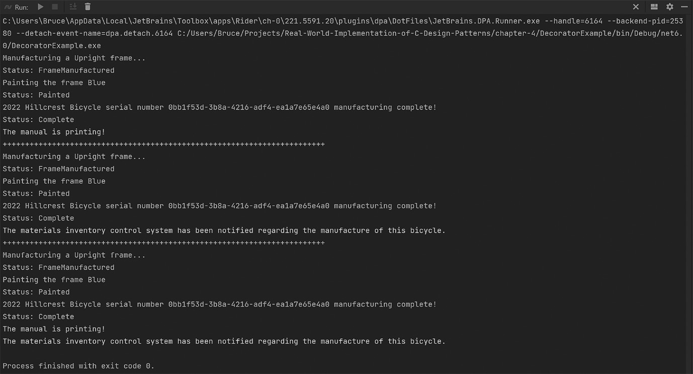
Figure 4.3: The output from the run of Program.cs for the DecoratorExample project (to save space, the output from the undecorated RoadBike is not shown).
You can see why the Decorator pattern is a crowd favorite among developers. You can use it when you need to add behaviors to an object without breaking existing implementations. Decorators can be used to create layers of business logic that can be stacked or combined as needed. For example, only bikes sold through the dealership network will need the DocumentedBicycle decorator, but all of them that use raw materials from our supplier will need the NotifyingBicycle decorator. If we make a bicycle with raw materials from another source that won’t be sold through the dealer network, then we do not need any of the decorators.
You can also use a decorator to extend classes that are awkward or impossible to extend through regular inheritance. Consider a class that is sealed, meaning it can’t be extended through inheritance. You can still extend it using a decorator! This can result in you feeling as though you’re an outlaw. This is normal and may lead you to obtaining a black cowboy hat and learning the lyrics to every song written by Johnny Cash. You’ve been warned.
The Façade pattern
“Ugh!” Phoebe exclaims. It’s 4 a.m. at Phoebe’s workshop. Her formerly white lab coat is covered in grease and she’s wading through aluminum shavings shed by an industrial lathe. She’s trying to build one of her robotic arms. She has several different designs, but this one is a heavy model that’s bolted to the floor. There are three variations of the arm. One arm is equipped with a welder used to weld the aluminum alloy bicycle frames together, another one has a buffer used to perfect the finish on the bicycles after they are painted, and the last one is equipped with a gripper used to hold the bicycle during assembly. Phoebe wanted to build several arms of each type. She was constrained by her budget and could only afford to build 10 arms. She decided the best combination for the arms would be three welders, three buffers, and four grippers. After whiteboarding the process, she realized her factory would not be able to keep up with the demand generated by the sisters’ stellar marketing campaigns. The Kickstarter alone had already generated hundreds of orders and the factory wasn’t even operational yet! Phoebe was having trouble coming up with a way to make this factory work.
Her sister Kitty had been working on the control software. The two had agreed on how the software would work in advance of creating the robotics because sometimes making the software before the hardware is practical. The software design is fluid and easy to change. It can drive the hardware design, which is less fluid and more expensive to change. This is one of those cases. On a whim, Phoebe pulls Kitty’s GitHub repo and switches to the branch where Kitty had designed the object structure for the control arms.
Phoebe finds Kitty’s implementation of the Decorator pattern and it gives her an idea. She can think of the attachments for the robot arm as decorators! This way she can make 10 arms, but the arms can perform whatever action is needed by switching the decorator. To be clear, Phoebe isn’t creating software. She’s taking inspiration from the Decorator pattern and making a robotic arm with interchangeable attachments, thus allowing the basic arm to perform many functions as needed without building a new arm for each task.

Figure 4.4: Phoebe finds inspiration in the Decorator pattern.
This is fantastic! However, there’s another problem. Each attachment will be built from components from different suppliers and each will have a different API to control the arm’s attachment.
A few weeks ago, Kitty left the s mall town of Alpine, Texas, where she was finishing up her Industrial Design degree at Sul Ross University. She drove her bright yellow Jeep Wrangler eight hours northeast to Dallas, Texas where her sister Phoebe was finishing her studies in engineering at Southern Methodist University. The purpose of Kitty’s visit, aside from the superior collegiate nightlife in Dallas, was to research and source potential parts for their factory robotics. They already had access to some of the more basic needs for manufacturing bicycles. At one point during their father’s career, he had spent a few years working for a helicopter factory in Fort Worth, Texas. Fort Worth is adjacent to Dallas and the residents refer to the area as the Dallas Fort-Worth metroplex. During their father’s time at the helicopter factory, he made many contacts that could help the girls achieve their goals. Everything they needed from machine shops to advanced computer-controlled laser cutting and fabrication was but a phone call away. The electronics, however, were a different story. The girls had decided to develop the robotics using readily available commercial off-the-shelf (COTS) components.
Servomotors are electrical motors that allow for precise control of angular or linear positioning, along with velocity and acceleration. They are widely deployed in the development of robotic and human-controlled industrial machinery. The objective for Bumble Bikes is to have an automated factory. Kitty began looking into microcontrollers. Microcontrollers are tiny computers that allow application programmer interface-(API-) level interactions to control anything, including servomotors. The servomotors might be connected to the computer using pin connectors, sometimes called “hats”, that seat onto the microcontroller’s printed circuit board. The local computer store in Dallas had a robust section of their supermarket-sized facility dedicated to the purveyance of microcontrollers, servomotors, and all the related electronics needed.
One week and one large workbook of Libre Office Calc spreadsheets later, they had a working bill of materials for building the robot arms and their three different attachments. Assembling the parts into an electrically viable robotic arm is elementary. The hardest part is writing the software. The girls sourced three different microcontrollers with three different APIs for each arm attachment: one for the grabber, one for the welder, and another for the buffer.
A simple solution would be to write a stovepipe application that calls the APIs directly based on any required logic dictated by the needs of the manufacturing process. The sisters’ recent experience with factory patterns has trained them to be wary of such strategies. Quick and easy solutions are neither sustainable nor maintainable in the long term, and they are thinking long-term. They want to build their robots once and those robots, being well maintained, conceivably could run forever.
One of Kitty’s professors, Professor Charles Dexter Ward, had taught a class titled Introduction to Smart Product Design. It was an entire semester on the exact problem the girls are solving: how to design efficient automated systems using sensors and microcontrollers. Dr. Ward had cautioned Kitty and her academic colleagues about vendor lock-in. Kitty and Phoebe are starting a business by turning a passion project into an enterprise they can pass to their children and grandchildren. It doesn’t make sense to trust that the microcontrollers they buy now, and their related APIs, will remain unchanged for the long term or even a few years into the future. By tightly coupling to the current APIs directly, the sisters would be trusting that the API developers they use today will remain in business as long as Bumble Bikes. This would also assume that the APIs will continue to evolve and be maintained in accordance with their application’s needs. Naturally, this would be a very naïve assumption.
A safer bet is that new microcontroller APIs will be introduced into the market and from different companies every few years. The method signatures and the way the API itself is invoked will be different than they are today. Consider common technology for remote API calls 20 years ago. Common Object Request Broker Architecture (CORBA) was replaced by Simple Object Access Protocol (SOAP). SOAP, in turn, has been entirely displaced by Representational State Transfer (REST), common in web development and the Internet-of-Things (IoT) industry, which is still nascent in the year 2022. I’ll wager many well-trained software developers reading this book have little to no exposure to CORBA or SOAP, just as your descendent colleagues will likely have something very different from REST. Any system that is tightly coupled to any API has a life span equal to the shortest life span of its tightly coupled components. Kitty has taken this particular lesson to heart. Within the software, Kitty had represented the control arm with an interface that implemented the robot arms performing abstract operations. These can be mapped to the API. She’s using the Façade pattern.
Façade, in regular English, or in this case, French, means “face”. In architecture (the kind with buildings, not software), it refers to the front of a building. A façade is usually ornate and represents what designers call curb appeal. One of the most famous façades I can think of is the castle at Walt Disney World in Florida, seen in Figure 4.5. A sidenote: Dear Internal Revenue Service, please accept my amended return with my deduction labeled “book research trip to Disney.” It was purely business, I assure you.

Figure 4.5: The front façade of the castle at Walt Disney World in Florida presents an ornate appearance to the outside world.
In software architecture, the Façade pattern works in reverse. Instead of a fancy ornate face to an object or API, it’s a simplified point of access. This nifty pattern can insulate your programs from vendor lock-in by situating itself between your code and the APIs you’re calling. As an added bonus, the façade also allows you to simplify the interface to the API, or even multiple APIs by only exposing the parts that matter.
In the case of Bumble Bikes, Phoebe and Kitty only need basic functions that allow the robotic arm attachments to move and then call the specific API routines that allow for welding, buffing, and grabbing. The respective APIs could have thousands of exposed objects, methods, and properties between them, but we only need a few. Likewise, there might be a dozen of these APIs, but from our code’s perspective, there is one library we’re calling. The API could even be called in a non-obvious way such as CORBA (hopefully not), REST, or directly as an imported assembly dependency. The façade would take care of all this seamlessly. When the APIs change in future releases or are replaced with different APIs from different vendors, you only need to replace the façade. The underlying code remains untouched. If you’ve used an Object Relational Mapper (ORM) with a database, that qualifies as a façade because it gives you simplified access to the database. This often allows you to switch out the database, say from Oracle to SQL Server, without changing your code.
This is how Kitty solved the API problem in the software. She created an interface that defined the behaviors of the robot arms. Then, she created a decorator, which is code that implements the interface. She then wraps the API calls, successfully mapping the abstractly defined behaviors to the specific calls to the API. Kitty, by designing the software in this way, has broken the dependency on the APIs, and by extension, prevented vendor lock-in. Any API can be decorated or wrapped following Kitty’s behavioral interface. When the next generation of microcontroller APIs becomes available, Kitty just needs to write a wrapper for the new API that conforms it to her software’s requirements encapsulated in the interface. The robotic control software remains closed for modification. This would not be the case if she tightly coupled it to the microcontroller’s API. Had she done that, every revision to the API would require a partial rewrite, along with serious testing and validation efforts for Kitty’s entire software suite. How often have you encountered, or even performed, a fix to one part of your software and the fix breaks something somewhere else? Have you ever said, “That’s impossible! There’s no way changing something in library A could affect the operation of library B!”? This is indicative of a program built on tightly coupled operations. Changing anything can and will have a cascading effect. The more complex the system, the more likely some stage of the cascade will have a deleterious effect on the overall system. This has been avoided by using the Façade pattern. While closed for modification, Kitty’s program is open for extension because she can easily add new wrappers that follow the interfaces used by her software. She need only develop and test the new software, not the entire control program. The program at large is insulated from rippling failures through de-coupling. Kitty’s engineering notebook documents her implementation of this pattern using Figure 4.6:
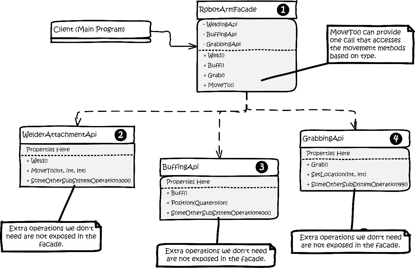
Figure 4.6: Kitty’s engineering notebook diagram of her implementation of the Facade pattern.
The parts of the pattern implementation can be explained by the numbers:
- The RobotArmFacade class is consumed by the client in place of direct references to the three third-party APIs represented by numbers 2, 3, and 4 in the diagram. Note the SomeOtherSubSystemOperation300(), SomeOtherSubsystemOperation400(), and SomeOtherSubSystemOperation99() are my clever way of hinting these third-party APIs are massive without drawing a diagram that fills the page with imaginary API methods. Our application only needs a few of these methods, so only those we need are exposed in the façade.
- WelderAttachmentAPI represents a third-party library, perhaps a NuGet package, that controls the welding arm attachment on Phoebe’s robot arm.
- BuffingAPI represents a third-party library, perhaps a NuGet package, that controls the buffing attachment.
- GrabbingAPI represents a third-party library, perhaps a NuGet package, that controls the grabbing attachment.
Note that many of the methods within the three third-party classes are similar.
WelderAttachmentAPI exposes MoveTo(int, int, int), allowing the control software to position the welding attachment in three-dimensional space. BuffingAPI uses Quaternion, which is a three-dimensional coordinate combined with an angular rotation. If you ever work with the Unity3D game engine, which uses C# as its flagship coding language, you’ll get to know and love quaternions despite their very complicated mathematical nature. Thankfully, with the Façade pattern, you don’t need to fully understand the inner workings, such as Euler angles and the concept of gimbal lock, to use them. GrabbingAPI provides SetLocation(int, int) with two coordinates since that attachment only needs to move in two dimensions.
All three APIs have a common feature that moves the robot arm into position, but they are not identical in the way they are implemented or called. Each has a different method signature. This is a perfect use case for a façade because you can expose a single method to control movement and selectively call the correct API method based on which arm attachment is in use.
Similarly, each API has some method for activating is main function: Weld(), Buff(), and Grab() respectively. Again, the façade can hide the complexity of calling multiple methods. While it may seem they achieve different goals, we can hide that complexity behind a single method that calls the correct API method based again on the type of attachment in use.
Let’s look at the code in the RobotArmFaçade class. First, we have an enum that defines the attachments:
public enum ArmAttachments { Welder, Buffer, Grabber }Next comes the class itself and its constituent member variables:
public class RobotArmFacade
{
  private readonly WelderAttachmentApi _welder;
  private readonly BuffingApi _buffer;
  private readonly GrabbingApi _grabber;
  public ArmAttachments ActiveAttachment;
You might note a similarity here with the Decorator pattern. We have private instances of the three APIs in the façade itself. It will be the job of the façade class to pass instructions through to the correct API in the correct format. The private members are initialized with a constructor:
public RobotArmFacade(WelderAttachmentApi welder,
    BuffingApi buffer, GrabbingApi grabber)
  {
    _welder = welder;
    _buffer = buffer;
    _grabber = grabber;
    ActiveAttachment = ArmAttachments.Welder;
  }
The ActiveAttachment member is arbitrarily set to default to the welder. Next, our façade will expose the methods for activating the currently active attachment. If it’s a welder, it will weld. A grabber will grab and a buffer will buff, but it doesn’t make sense to expose the methods by name. The façade makes things simpler. Kitty elects to call the façade method Actuate() and this method determines what is actually called behind the curtain:
public void Actuate()
  {
    switch (ActiveAttachment)
    {
      case ArmAttachments.Buffer:
        _buffer.Buff();
        break;
      case ArmAttachments.Grabber:
        _grabber.Grab();
        break;
      case ArmAttachments.Welder:
        _welder.Weld();
        break;
      default:
        throw new ArgumentOutOfRangeException();
    }
  }
Lastly, we need to expose a simple way to move the arms and position the attachments. This one requires a little more thought since each API method has a different method signature. Kitty decides the obvious solution is to pick the most complicated requirement, Quaternion. Quaternions are part of the .NET System.Numerics library. This struct holds four values, W, X, Y, and Z of the Single type per the documentation. Since it is the most complicated requirement, it can be made to service the simpler method signatures by ignoring the parts of the quaternion we don’t need:
public void MoveTo(Quaternion quaternion)
  {
    var roundX = (int)Math.Round(quaternion.X, 0);
    var roundY = (int)Math.Round(quaternion.Y, 0);
    var roundZ = (int)Math.Round(quaternion.Z, 0);
The two APIs, WelderAttachmentAPI and GrabbingAPI, need integers. First, we’ll convert the single numbers in the quaternion into integers by rounding as shown in the preceding code. Next, we’ll call the appropriate API based on the active attachment:
    switch (ActiveAttachment)
    {
      case ArmAttachments.Buffer:
        _buffer.Position(quaternion);
        break;
      case ArmAttachments.Welder:
        _welder.MoveTo(roundX, roundY, roundZ);
        break;
      case ArmAttachments.Grabber:
        _grabber.SetLocation(roundX, roundY);
        break;
      default:
        throw new ArgumentOutOfRangeException();
    }
  }
The buffer attachment requires a quaternion, so our code will just be passing through the original argument. The X, Y, and Z coordinates can be made compatible with the other two method signatures by rounding the numbers and ignoring anything in the quaternion you don’t need.
Phoebe decides her assembly line should be very simple. The robotics generally only need to worry about where along the assembly line they are positioned, so her control program will vary the X coordinate in every case. As a further measure of control, Phoebe decides to create a control program that knows precisely what the X coordinates are for each station on her assembly line.
Her control program consists of this code:
const int numberOfAssemblyStations = 20;
const float consistentY = 52.0f;
const float consistentZ = 128.0f;
const float consistentW = 90.0f;
First, we see a set of constants. We have a maximum of ten robotic arms owing to Phoebe’s material and financial constraints. Since the arms can be made to work as a team, Phoebe discovers she can power 20 stations by systematically moving the robots from station to station, swapping out arm attachments as needed. She carefully calibrates her equipment and finds the ideal Y and Z coordinates. She sets them as constants along with a default rotational angle of 90 degrees, which works with all her processes.
Next, Phoebe creates an array to hold the coordinates of her 20 stations as quaternions:
var assemblyStations = new Quaternion
    [numberOfAssemblyStations];
Since the assembly line is literally a straight line, it is easy to evenly space the stations 25 feet apart along the line’s X axis. A simple loop can then pre-populate the array of quaternions that represent the workstations on the assembly line:
for (var i = 0; i < numberOfAssemblyStations; i++)
{
  var xPosition = i * 25.0f;
  assemblyStations[i] = new Quaternion(xPosition,
      consistentY, consistentZ, consistentW);
}
We are now ready to set the robotic dance in motion.
Let’s instantiate our RobotArmFacade, set the attachment to a welder, and move it to station zero, which is the first position in the array of quaternions. Once it’s there, we’ll tell it to perform a weld using the Actuate() method on the façade:
Console.WriteLine("RobotArm 0: Robotic arm control system
    activated!");
var robotArm0 = new RobotArmFacade(new
    WelderAttachmentApi(), new BuffingApi(), new
        GrabbingApi());
Console.WriteLine("Initializing welder function in arm 0");
robotArm0.ActiveAttachment = ArmAttachments.Welder;
robotArm0.MoveTo(assemblyStations[0]);
robotArm0.Actuate();
Next, let’s move the arm to station 3 where we need a buffer to smooth out a metal extrusion on a bicycle frame. Once the arm is in place, we’ll buff using the Actuate() method:
Console.WriteLine("Initializing buffer function in arm 0");
robotArm0.ActiveAttachment = ArmAttachments.Buffer;
robotArm0.MoveTo(assemblyStations[3]);
robotArm0.Actuate();
Splendid! The arm is now needed to grab a part and hold it in place for painting at station 7:
Console.WriteLine("Initializing grabber function
    in arm 0");
robotArm0.ActiveAttachment = ArmAttachments.Grabber;
robotArm0.MoveTo(assemblyStations[7]);
robotArm0.Actuate();
Initially, we needed to deal with three different APIs from three different vendors to work with three different pieces of hardware. By using the Façade pattern, we were able to deal with one common interface for all three APIs, which isolates the bulk of our code from changes made in the API. When the API changes, we may need to change the façade, but we won’t need to change anything else.
The Composite pattern
Phoebe continued to work on the electronics. Kitty, however, was starting to worry about some of the fundamental considerations for her designs. Initially, the girls had agreed to use commercially available components, but Phoebe realized they could manufacture all the parts they need themselves. That way, assuming Bumble Bikes had access to all the raw materials, such as aluminum alloys, plastic, and rubber, they could have tighter control over the cost, durability, and weight of their final product. These factors influence everything from how Bumble Bikes sources its raw materials to the final sales price. The final sales price is factored by adding in the cost of goods sold, or in this case, the cost to manufacture, package, and deliver a bicycle. Kitty had some preliminary spreadsheets on her iPad. They were complicated, though. Kitty really wanted to ditch the two-dimensional thinking presented by her spreadsheets and come up with a better way to represent the cost of making a bicycle.
Kitty opened her backpack and her heart sank. Her iPad, or what was left of it, spilled on to the worktable as a collection of broken glass and jagged plastic shards. She remembered her crash at Big Bend last weekend. She had misjudged the drop on a 3-foot (1-meter) ledge on Black Gap Road, flipped over her front handlebar, and landed on her back. Her backpack, which contained her iPad, had broken her fall. Everything was on that iPad! Thankfully, her father had drilled the number one house rule into her head. “Always protect the gear!” he would say. “We make our livelihood with our tablets and our laptops. Others use them to play games and watch movies. There’s nothing wrong with that, but we use ours to make our mortgage, so take care of your gear!” He would usually shout this epithet very early in the morning when he would invariably trip trying to avoid someone’s tablet, phone, or computer that had been left on the floor right along the path he took as he sleepily lumbered to the kitchen in the mornings in search of caffeine. Owing to this sage wisdom, the tablet was backed up. When Kitty had purchased it in Dallas from her favorite computer store, she had opted to get the extra 99 USD replacement guarantee that covered everything, including accidental damage. The new iPad arrived in the mail the next day and Kitty, being a student of industrial design, reveled in the unboxing of her new digital compatriot.
For all the criticisms she had about Apple products, such as the inability to upgrade or repair them, there was one thing nobody could deny. They have the coolest packaging of any product in the tech industry. The packaging itself is a work of industrial art: from the heavier than necessary gauge of cardboard to the way all the packages fit together to take up as little space as possible.
As Kitty was waiting for her cloud backup to restore all her data and apps, a lightning bolt thought struck her. Apple had solved the very problem she was considering. The way the packages fit together, where some are inside of others, reminded her of a tree structure. The iPad shipped with the tablet, a charger, a USB-C style cable, and a tiny box containing a beautifully printed instruction manual that everybody just throws away. There was a warranty card and a few other printed cards touting Apple’s responsible stance on the environment and an advert for AppleCare, Apple’s own service plan. The iPad itself was housed inside a coated cardboard insert where all the pieces in the package fit together precisely. The charger and cord fit in a niche below a sunken niche carved out for the iPad itself. Everything was coated with plastic, so nothing would be marred or scratched during shipment. The intricate package, depicted in Figure 4.7 in a way that will not get me sued, contained as many small boxes and cardboard pieces as the actual electronics they held. Naturally, a product designer at Apple could tell precisely how much any of the smaller boxes or wrapped components within the larger package weighed at any time, as well as how much each of the intricate die-cut cardboard components cost to make. That designer probably agonized for months looking for ways to shave fractions of pennies off the package material cost, just as the iPad’s designers had stressed over weight, power, and heat concerns:

Figure 4.7: Kitty’s new tablet came intricately packaged. She realized it could be modeled as a tree structure, and perhaps bicycle components might be modeled in the same way.
So far, Kitty had successfully created class models for high-level bicycle components, such as the frame. She and Phoebe had committed themselves to the idea that they would manufacture everything for the bicycles themselves, including the crankset. The crankset consists of all the parts that make the bicycle move when you push down on the pedals. Bumble Bikes intended to position itself on the market as a cut above big-box stores in terms of its build quality. That meant every gram would be scrutinized by sophisticated customers who were conditioned to having to buy a bicycle, discard most of the components it came with, and replace them with better, lighter components. There is always a perfect balance between the weight and cost of the crankset for many riders. The racing community will pay a premium for parts that are several grams lighter, while casual riders want a product that’s less expensive and they don’t mind the extra weight.
The crankset, as with the boxes, can be modeled as a tree, as we’ll soon see. If you’re not personally familiar with the parts on a bicycle that comprise a crankset, and you’re curious, see Kitty’s CAD drawing in Figure 4.8 where she was kind enough to diagram most of them for us:

Figure 4.8: The crankset for a typical bicycle involves components that can be nested in a tree-like structure to solve our immediate problems with cost and weight.
When you are presented with modeling a tree-like structure of objects that can conform to a common interface, you should immediately think of the Composite pattern. The Composite pattern allows you to compose a tree of objects and then work with the structure as if it were a single object. The tree is composed of containers and leaves. A leaf is a tree element that doesn’t have any sub-elements. A container is a tree element that has other leaves and containers within it. Graphically, this looks similar to a file folder structure on your computer. The files are leaves and the folders are containers:

Figure 4.9: The file structure of your computer’s hard drive is represented as a tree consisting of leaves (files) and containers (folders).
We can model part of our group set this way as well. For our mechanically inclined readers, I’m not necessarily suggesting these parts literally fit inside each other in the physical world. I’m suggesting they can be modeled this way to solve the problem at hand in terms of weight and cost. In this model, the crankset consists of the bottom bracket, which is basically a big hole at the bottom of the bicycle frame fitted with bearings, and a shaft extends through the bottom bracket. The shaft is connected to a set of chainrings. Most bicycles have one, two, or three chainrings depending on what kind of bicycle it is. Road bikes usually have two: a large chainring for general riding and a small chairing that is used to climb hills. In our model, the small chain ring is treated as a leaf where all other components so far have been containers.
The chainrings connect to the crank arms, which are one big piece, even though they might appear to be two separate arms. The arms attach to the left and right pedals, which are the leaves and the end of our tree structure.
The composite pattern allows you to work with complex tree structures elegantly by allowing you to make full use of recursion and polymorphism. Just be careful that you work with classes that have a very common interface. You might be introducing code smell if you must shoe-horn a bunch of classes that don’t really fit together. This pattern pairs nicely with the Builder pattern already in use because the builder can be made to assemble the tree structure. The basic structure of the composite pattern is shown in Figure 4.10:

Figure 4.10: The Composite pattern.
Let’s understand this figure in detail:
- The Component class will implement some interface with the methods needed to access the overall functionality. Here, we’re calling that Run(). Components can contain leaves and other components.
- The Leaf class represents nodes in the tree that can’t contain anything else.
- The Composite object allows for the creation and maintenance of a tree structure using components and leaves.
- The client program accesses the composite tree as it needs and can treat simple and complex objects identically.
I want to reiterate that we are not attempting to model the physical structure of our bicycle. This model is a cost model and defines the relationships within a group of components, not the order of physical assembly. The fields we’re interested in are cost and weight, and those fields will form an interface that describes the common properties of any bicycle component regardless of its form, construction, or purpose.
Kitty’s version looks as follows in Figure 4.11:
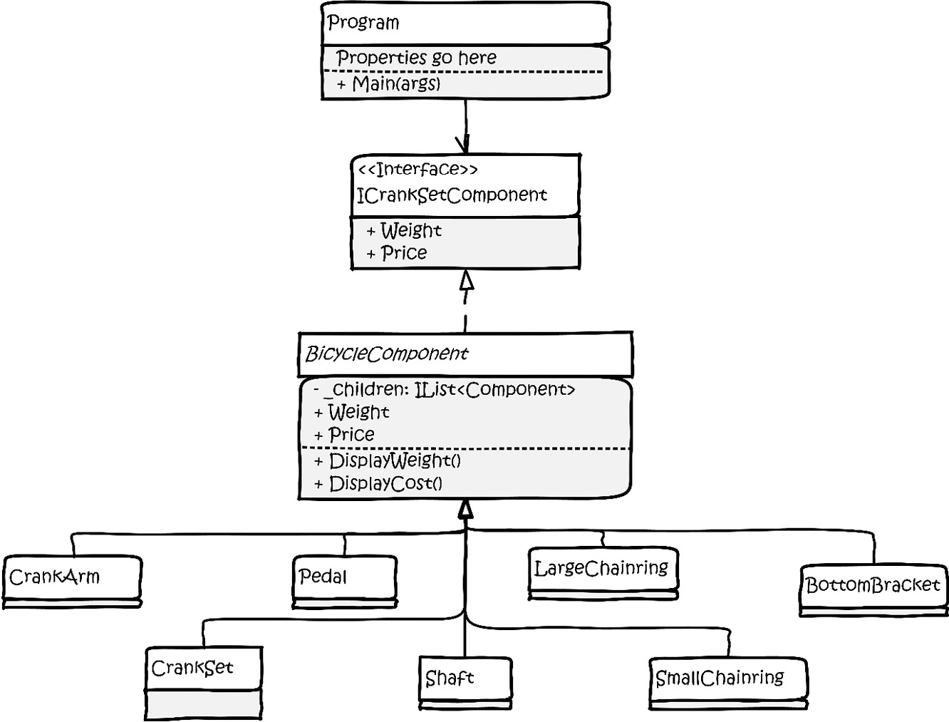
Figure 4.11: Kitty has changed the structure of the basic pattern found in Figure 4.x to suit her needs. Note this isn’t the diagram of the full hierarchy, it’s just the structure of the pattern
The implementation of this pattern only requires one abstract class and a horde of concrete classes based on the abstract class. The following are the contents of Kitty’s abstract BicycleComponent class, which forms the vital common interface needed by the pattern. We need two private properties to hold the weight and cost values of the component:
public abstract class BicycleComponent
{
  private float Weight { get; set; }
  private float Cost { get; set; }
Next, we need a list to hold any subcomponents. Kitty specified an interface for the type instead of directly coupling to the List<> class:
public IList<BicycleComponent> SubComponents;
These three properties are initialized in a constructor where we pass in weight and cost as floats. The SubComponents list is initialized as an empty list:
  protected BicycleComponent(float weight, float cost)
  {
    SubComponents = new List<BicycleComponent>();
    Weight = weight;
    Cost = cost;
  }
Next, we need two methods to display the weights and costs of the components along with any subcomponents. These can leverage recursion to print out the entire tree, which is handy for Kitty’s cost analysis. We only need to do this on containers, not leaves, since leaves will be printed with their containers. We determine whether we’re dealing with a leaf by checking SubComponents.Count. If it is zero, we are dealing with a leaf, and we simply return. Otherwise, we loop and print the weight and cost of the subcomponents:
  public void DisplayWeight()
  {
    if (SubComponents.Count <= 0) return;
    foreach (var component in SubComponents)
    {
      Console.WriteLine(component.GetType().Name + " weighs
          " + component.Weight);
      component.DisplayWeight();
    }
  }
Here, we do the same thing with cost:
  public void DisplayCost()
  {
    if (SubComponents.Count <= 0) return;
    foreach (var component in SubComponents)
    {
      Console.WriteLine(component.GetType().Name + " costs
          $" + component.Cost + " USD");
      component.DisplayCost();
    }
  }
}
The concrete code for the Composite pattern is generally very repetitive, as you’ll see. In fact, Kitty does something here she doesn’t do anywhere else. She makes one file containing many classes. She names the file CompositeParticipants.cs, the partial contents of which follow in the code below. She did it this way because effectively it’s a collection of very simple concrete classes that inherit from a base class. If you want to see the whole class, consult Kitty’s code in the chapter’s sample code project:
public class Pedal : BicycleComponent
{
  public Pedal(float weight, float cost) : base(weight,
    cost)
  {
  }
}
public class CrankArm : BicycleComponent
{
  public CrankArm(float weight, float cost) : base(weight,
    cost)
  {
  }
}
public class LargeChainRing : BicycleComponent
{
  public LargeChainRing(float weight, float cost) :
    base(weight, cost)
  {
  }
}
As you can see, this isn’t rocket surgery. Every part is simply modeled as a concrete implementation of the abstract class. I’ve shown three classes here. There are seven in total that all look the same save for the class name.
At first glance, this might seem odd until you see how the composite’s tree is constructed in the client code within the Program.cs file. Within that file, Kitty builds the tree from the bottom up. This isn’t a requirement, but it does make it easy to understand. The leaves at the bottom of the tree are the petals or pedals:
var leftPedal = new Pedal(234.14f, 11.32f);
var rightPedal = new Pedal(234.14f, 11.32f);
The pedals connect to the crank arm. I’m suddenly reminded of the old song Dem Bones where the toe bone is connected to the foot bone. The foot bone is connected to the heel bone. The song continues up to the head bone followed by an invocation of the songwriter’s creator. Here, the pedal bone is connected to the crank arm bone, except they aren’t bones:
var crankArm = new CrankArm(432.93f, 34.32f);
crankArm.SubComponents.Add(leftPedal);
crankArm.SubComponents.Add(rightPedal);
We create the instance of CrankArm, then add the pedals to its SubComponents list. crankArm is connected to largeChainRing. So is smallChainRing, which itself becomes a leaf:
var largeChainRing = new LargeChainRing(57.0983f, 13.53f);
var smallChainRing = new SmallChainRing(52.57f, 11.33f);
largeChainRing.SubComponents.Add(smallChainRing);
largeChainRing.SubComponents.Add(crankArm);
The large chainring is connected to the shaft:
var shaft = new Shaft(82.03f, 19.55f); // can you dig it?
shaft.SubComponents.Add(largeChainRing);
The shaft fits through the bottom bracket:
var bottomBracket = new BottomBracket(284.834f, 11.51f);
bottomBracket.SubComponents.Add(shaft);
That’s our crank set, but I’ll add a top-level instance of CrankSet and pass in zeros for the cost and weight since the crank set itself comprises its subcomponents:
var crankSet = new CrankSet(0f, 0f);
crankSet.SubComponents.Add(bottomBracket);
Now for the magical part of our show. We’ll call the two methods and get a recursive detail of the whole structure:
Console.WriteLine(" ---------- Weights -----------------");
crankSet.DisplayWeight();
Console.WriteLine(" ------------ Cost ------------------");
crankSet.DisplayCost();
The result of the run is shown in Figure 4.12:

Figure 4.12: The run results of our Composite pattern project.
The Composite pattern is used whenever you need to process a hierarchical structure as a tree. The main requirement for the pattern to be effective is that every node in the tree must conform to a common interface. If that can be managed, you can use this pattern to process the tree in any manner you might need. You can add new class types to your tree, so long as they conform to the common interface. Using this pattern, you can create novel processing capabilities while honoring the open-closed principle. Recursion and polymorphism can be exploited to expedite your processing. The client code will treat nodes and containers identically since they have a common structure, which is really the hard part. You have to find a way to make everything in the tree conform to the common interface, which isn’t always easy.
The Bridge pattern
The Bridge pattern is a structural design pattern that lets you split a large class or set of closely related classes into two separate hierarchies: abstraction and implementation. Kitty and Phoebe set up a Kickstarter page to promote Bumble Bikes and gauge the interest on the market. Backers can preview and pre-order the Palo Duro Canyon Ranger, Bumble Bike’s flagship mountain bike design. The project has been well received, but the Kickstarter backers are complaining about the lack of color choices on the bikes. In the original design, the girls purposefully limited the color choices because they were using inheritance for almost everything. The problem with using inheritance is becoming a clear theme: it can lead to a run-away proliferation of classes, as seen in Figure 4.13. Can you imagine supporting 20 colors per bicycle model, and expanding to 20 models of bicycles? That’s a lot of subclasses!

Figure 4.13: Class proliferation may sound as if it’s a Marxist political construct, but it becomes a problem when you over-use inheritance (we clearly need a better way to represent a finite set of supported colors for our bicycles).
Perhaps the simplest way to solve this is to simply create a property on your base bicycle class to hold the color. Maybe have it store a common color structure such as Red Green Blue (RGB) or Cyan Magenta Yellow Black (CMYK), which is the color model used by printers. This works fine if you’re dealing 100% with software and you need to represent a color within a gamut supported by your user’s graphics card or printer.
In an industry such as bicycle manufacturing, this won’t work, because we aren’t just representing any possible color of light or paint. We need to represent a finite set of paints to be mixed and applied using machinery. This dimension of realism means there are limits to how the color system can work. The girls must keep the base colors and topcoats in stock, and they must take into account the setup and cleaning costs of their painting machinery. Limiting each bike to one available color handles all this nicely without any design problems. In effect, they were counting on controlling a variable in their software by making a single color a business requirement. As it turns out, the market won’t bear that constraint. Competitors can offer a range of colors. Phoebe herself remembers the most important aspect of her new bike when she was 9 was that it was pink. She didn’t care about where it came from or whether it had a fancy label on the frame. It had to be pink.
When we looked at the Decorator pattern earlier in this chapter, the problem was similar. We added external features, such as bells and lights, which could also be represented with an exponentially growing tree of subclasses. So, why not use a decorator here? Perhaps, you could think of a paint job as a decorator. Decorators, though, are designed to stack. We can stack a bell, headlights, taillights, fenders, mirrors, and even bicycle theft alarms on top of one another within the object hierarchy to build the perfect bicycle without altering the abstract bicycle base class. There’s something not quite right about stacking paint jobs or even stacking your bell or lights onto a paint job. The paint, conceptually speaking, is more a part of the frame than something that decorates it. Beware of learning a pattern and then wielding it as a golden hammer. The decorator doesn’t really fit here, even though not using the pattern has a similar side effect.
When you read about the Bridge pattern in the GoF book, and I always encourage you to go to the original academic sources when you can, you will find it couched in very academic language. They talk about a bridge between an abstraction and its implementation. We can vary each independently of one other by keeping the two separate. We have a business requirement for a new dimension that is an integral part of our bicycle’s frame and we need to vary that dimension independently of the abstract bicycle. When you want to vary two or more dimensions independently, while avoiding a combinatorically increasing number of subclasses, you need the Bridge pattern.
You can see a representation of the Bridge pattern in Figure 4.14. I may have had a little fun with the visuals, but it does make it easy to see why this pattern is called a bridge:
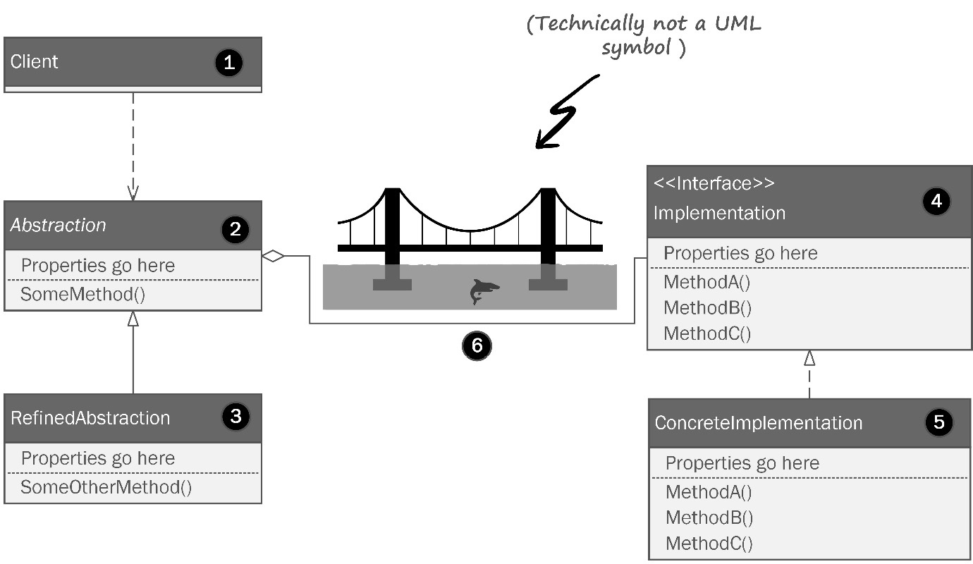
Figure 4.14: The Bridge pattern allows you to vary two sides of your object structure independently along two different dimensions.
Let’s review the elements of the Bridge pattern in our diagram by the numbers:
- This is the client that accesses the functionality in the abstraction.
- This is the abstraction side of the bridge. This is usually the class structure that you started with and the structure that worked well until you realized you had additional dimensions you needed to model.
- Refinements to the abstraction are subclasses that make sense and that don’t create a runaway multi-dimensional class structure. We have several refinements by way of four different types of bicycles that inherit from the abstract bicycle class.
- The implementation interface is on the other side of the bridge. This is where you model the dimension that will vary independently of the abstraction. Note the bridge itself between the two consists of a compositional relationship. The abstraction has an implementation of the second dimension.
- This is the concrete implementation of the second dimension based on the interface.
- That’s a shark. Studies have shown that you are 68.342% more likely to be attacked by a shark if you don’t use the Bridge pattern to decouple your complicated classes. It doesn’t even matter if you live inland. Nobody knows why. It’s SCIENCE! Don’t argue.
Let’s take a look at Kitty’s version of the Bridge pattern diagram applied to the bicycle paint problem in Figure 4.15:

Figure 4.15: Kitty’s whiteboard rendition of the bridge pattern applied to her paint problem.
“Whoa, whoa, WHOA! Wait one fluffy minute!” Phoebe exclaimed as she stomped her foot on the ground. “You can’t do this! The only way to make this work is to break the open-closed principle! We’ve held this rule as sacrosanct!” Kitty stared blankly at the board. Phoebe is right. She usually was, especially when she stomped her feet, a trait she got from her mother.
“We already have a color attribute in the abstract Bicycle class,” Kitty observed. “But because it’s a stinkin’ enum, we can’t extend it, nor can we subclass it,” Phoebe added. “What about a decorator?” Kitty asked. “Maybe, but it seems as though we’re going to wind up with a lot more code and complexity than we would if we just changed the original design,” Phoebe said. Neither wanted to give up. For the next few hours, the two pored over articles on other patterns that might help them. The problem here is that the original model used an enumeration to define the colors. A limitation of the C# language holds that an enumeration cannot be extended.
If they subclass or decorate the original IBicycle interface or the abstract Bicycle class, they’ll need to add the PaintJob attribute, but they’ll be stuck with the existing Color attribute. Inheritance doesn’t give us a way to hide or remove deprecated code. Covering it up with a façade doesn’t feel right either. Even if you covered the unused member with a façade, it would also change the interface you use to work with the bicycle classes.
“Gaga! We are going to have to change the type in the bicycle base class!” Phoebe said angrily. “Gaga” is a word Phoebe had trained herself to say in place of less socially acceptable words, such as the ones most people say when they stub their toe really, really, hard. The two railed against the realization with the fervor of defense attorneys trying to free an innocent man accused of capital murder. They pored over software engineering books and books on patterns. A common thread in all those books is that never once did any of the authors ever make a design mistake. They either presented trivial examples such as shapes, circles, and squares, or they presented patterns in a way that was too hypothetical – ClassA inherits from ClassB, and so on. The examples weren’t very useful, but they were very safe, as far as examples go. The GoF book presents real-world use cases via a windowed software project mainly aimed at Unix users working with SmallTalk, which isn’t widely used outside of government and academic circles.
Late one night, the sisters found the clarity that had been eluding them. Two of the most important books in the world of agile development with patterns are Robert Martin’s books titled Agile Software Development, Principles, Patterns and Practices, as well as the rewrite for C# developers titled Agile Software Development, Principles, Patterns and Practices in C#. The GoF book introduced the world to formalized software patterns, but Uncle Bob’s books introduced the world to SOLID and agile principles coupled with those patterns. Don’t worry. They aren’t tightly coupled. That would be a horribly recursive nightmare.
If you’re reading the e-book version of this book, assuming there is one, get out your e-highlighter for the next three sentences. Analog highlighters can be used on analog books.
Uncle Bob reminds us that it is impossible to foresee every design consideration ahead of time. Nobody is prescient, which is a point we made in the first chapter of this book. Lack of prescience leads to design problems that are usually solved with stovepipe-style fixes.
It may seem as though we’re abandoning our open-closed principle. You should never abandon the SOLID principles. But sometimes you must break them for the greater good. Martin’s books describe this as taking a bullet and realizing the opportunity to learn from the mistake. He also reasons for you to consider every element within your code that can be refactored in an identical manner with the hope that you need only to take one such bullet. In the real world, as software grows, you will need to adhere to good principles, but you can’t be shackled by them.
Patterns can help you avoid the need to change the base class, but occasionally you will need to change the design because not changing it will make everything worse. Equally as important is the exercise of removing dead code from the software. This too necessitates breaking SOLID principles. It is far better to remove the dead code than leave it in for the sake of dogma.
In this particular case, changing the way we implement the property allows us to serve our business requirements in a flexible way true to the spirit of SOLID principles without being fettered by them. This is a call you should find yourself making on rare occasions. Changing the interface to use the new IPaintJob interface adds significant business value to the overall design.
We now have a way to model the bicycle, which we’ve had for a while, and a business-savvy way to model the paint job. Kitty and Phoebe can now offer their customers bicycles in a variety of colors. We’ve gone from limiting customers to a finite set of one color per bicycle to a set that is limited only by the gamut of the paints. We’ve shifted from a software limitation on the business to a limitation of real-world chemistry and machinery. I’ve personally always held that business should define software, not the other way around.
The Bridge pattern isolates the Bicycle classes from being tightly coupled to an equally complicated model. There is little doubt that over time, the painting model and the bicycle model will continue to grow in complexity, but now they do so in isolation.
Let’s look at the code for the Bridge pattern. For this book’s example code, I’ll be leaving all the code we have written so far intact. In real life, I’d begrudgingly modify the IBicycle interface. For the sake of the book and continuity, I’ll be putting Kitty and Phoebe’s code into a slightly different format. Phoebe sternly objected, but the editor stepped in and she ultimately capitulated.
I’ll start by making a new interface to use in place of IBicycle. All I’m going to do here is take out the offending Color property:
public interface ISimplifiedBicycle
{
  public string ModelName { get; set; }
  public int Year { get; }
  public string SerialNumber { get; }
  public BicycleGeometries Geometry { get; set; }
  public SuspensionTypes Suspension { get; set; }
  public ManufacturingStatus BuildStatus { get; set; }
  public void Build();
}
The bridge we’re building has two sides. The bicycle side is represented by this new ISimplifiedBicycle interface, and the implementation side is used to independently model a complex object that describes how the bicycles might be painted.
Since classes and interfaces describing a paint job will probably be used across several different projects, Kitty adds a new namespace to the BumbleBikesLibrary we saw her create in Chapter 3. She adds a new folder called PaintableBicycle. The rest of the code presented in this chapter can be found in the library project which is in chapter-3/BumbleBikesLibrary/PaintableBicycle.
For the latter, Phoebe devised an interface she thinks can describe anything her robots can paint:
public interface IPaintJob
{
  public string Name { get; set; }
  public int Cyan { get; set; }
  public int Magenta { get; set; }
  public int Yellow { get; set; }
  public int Black { get; set; }
  public IPrimer Primer { get; set; }
  public IPaintTopCoat TopCoat { get; set; }
  public void ApplyPrimer();
  public void ApplyPaint();
  public void ApplyTopCoat();
}
Every paint job created in the system will have a marketable name, which is stored in the Name property. The paint system Kitty wants to use is based on the same CMYK color space used by traditional printing. She also intends to use a paint finish she calls TopCoat. Since this too is likely going to be reused later, it belongs in the library Kitty created in Chapter 3. You’ll find this in the book’s sample code in chapter-3/BumbleBikesLibrary/PaintableBicycle. The paint finish will make the bicycle’s paint job take on a beautiful glossy sheen and protect the paint from scratches and sun exposure. Here’s an interface that describes the paint finish:
public enum PaintTopCoatTypes { TopCoatClear, GlamorClear,
    TurboClear, HigherSolidClear }
public interface IPaintTopCoat
{
  public string Name { get; set; }
  public PaintTopCoatTypes Type { get; set; }
}
“Hold up, Kitty!” Phoebe exclaimed. “Why are we using another enum? That was nothing but trouble last time!”
Kitty defended her design decision by saying, “We were short-sighted thinking we could get away with one color per bicycle. But when it comes to primers and paint finishes, there are classifications for each that rarely ever change. The code for the primer is probably going to be reused, so Kitty puts the code in the library she created in Chapter 3. You can find it in chapter-3/BumbleBikesLibrary/PaintableBicycle. The PaintTopCoatTypes enum contains the same set that has been in use for several decades. The makers improve the chemistry in the products, but they never introduce anything revolutionary. The same goes for primer.” Kitty brought up her Primer interface:
public enum PrimerColors { Gray, White, Black }
public enum PrimerTypes {Epoxy, Urethane, Polyester,
    AcidEtch, Enamel, Lacquer, MoistureCure}
public interface IPrimer
{
  public string ManufacturerStockKeepingUnit { get; set; }
  public PrimerTypes Type { get; set; }
  public bool IsLowVoc { get; set; }
}
Naturally, a good paint job starts with a good primer. To expand on Kitty’s point, these primers have been around for a long time. Kitty put more in the enum than she’d likely use just to be careful. The girls source a few they might use, but for the most part, the good old-fashioned gray primer used for automotive painting seems to work best. She has fields for the manufacturer’s Stock Keeping Unit (SKU) so they can order the primer easily. She also has a property, isLovVoc, that tells her whether the paint is considered to be low in Volatile Organic Compounds (VOCs). If you’ve ever painted a room with regular house paint, you might remember the smell being very strong. You probably needed to open a window after a while to let the fumes out. When working with industrial paint, you must be very careful with fumes, the source of which is the VOCs. This property lets us be safe. If it’s false, we’d want to be sure to wear a respirator around the painting equipment.
The structure of the paint job model is taking shape. Compared to a simple color term, it is relatively complex. As you can see, the Bridge pattern truly helps us. The main objective of the Bridge pattern is to allow two complex object structures to be developed and maintained independently of one another. The bicycle models have gone through many interactions by name and have become more and more robust models. Now, we have this complex paint job model. The two need to go together, but a day could come when either the bicycle model or the paint model might undergo drastic changes. The bridge is, as with many of the patterns we’ve studied so far, insulating parts of our code from change while simultaneously making all of our code flexible and reusable.
To handle our use case for the Bridge pattern, I’ll make another interface that inherits from ISimplifiedBicycle called IPaintableBicycle. We’re doing it this way to maintain as much flexibility as we can:
public interface IPaintableBicycle : ISimplifiedBicycle
{
 IPaintJob PaintJob { get; set; }
}
Kitty and Phoebe have four bicycle designs that need to implement this interface. It makes sense to set up an abstract class to implement the interface:
public abstract class PaintableBicycle : IPaintableBicycle
{
  public string ModelName { get; set; }
  public int Year { get; }
  public string SerialNumber { get; }
  public BicycleGeometries Geometry { get; set; }
  public SuspensionTypes Suspension { get; set; }
  public ManufacturingStatus BuildStatus { get; set; }
  public IPaintJob PaintJob { get; set; }
The Build() method requires an update as well. The Bicycle class has a line that prints the color of the bicycle. We still need to do that, but instead of deriving it from the enum, we’ll work with the name of the paint job:
 public void Build()
  {
    Console.WriteLine($"Manufacturing a
        {Geometry.ToString()} frame...");
    BuildStatus = ManufacturingStatus.FrameManufactured;
    PrintBuildStatus();

    Console.WriteLine($"Painting the frame
                     {PaintJob.Name}");
We also need to apply the other parts of the paint job:
    PaintJob.ApplyPrimer();
    PaintJob.ApplyPaint();
    PaintJob.ApplyTopCoat();
    BuildStatus = ManufacturingStatus.Painted;
    PrintBuildStatus();
The rest of the class can remain the same. You will find the full code in the chapter’s source code available on GitHub.
The new paint system exceeds the Kickstarter backers’ expectations. Not only can Bumble Bikes support custom colors for every bicycle but they can also support custom gradient paint jobs. This is a feature rarely seen in the bicycle industry outside of shops specializing in custom paint and assembly.
The Bridge pattern can be implemented any time you have two or more class hierarchies that are complicated and need to be used together. At its core, the Bridge pattern is little more than composition. The reason it is recognized as a pattern is it becomes a thoughtful exercise in decoupling. It usually arises within the design phase. You start with a class and it gets more and more complex as you design it. Ideally, you find this growth in complexity when you are modeling the class, and you decouple it before it ever reaches code. In the real world, it comes up several iterations or even several years into the project, and you need to remember this has happened before. It will happen again. Eventually, it will happen to you. There is a solution, and that’s the heart and soul of software development patterns.
Summary
Kitty and Phoebe’s modeling of the bicycle products and the automated manufacturing process and apparatus is growing more sophisticated as the two learn and invent their new business. This is how it works, and from the outside looking in, I’d say they’re doing an amazing job. It is very normal for a software developer to be an expert at software design and development, but far less of an expert in their understanding of the business problems they are tasked to solve. Software projects are really an evolution involving the developer’s understanding of the business and the needs of their customers and stakeholders.
In this chapter, we learned several structural patterns that allow us to continue to make our software more sophisticated yet simple to maintain and extend. You’ve also noticed a common theme: the basic tools of inheritance and composition afforded by an object-oriented programming language are not, by themselves, enough to build robust software. These structural patterns allow us to use the tools of composition and inheritance to maximum effect without boxing our designs into a quagmire of spaghetti-like object hierarchies.
The Decorator pattern allows us to extend existing classes by decorating or wrapping new functionality around the original class. The decorators can stack as a Russian Matryoshka doll does, where one doll is nested inside another.

Figure 4.16: A Russian Matryoshka doll (each doll nests inside the larger one, the same way decorators wrap around base classes or stack on other decorators).
Phoebe mastered the Façade pattern, which allows us to abstract and insulate our software from complex dependencies. The pattern allows you to put a simple face on a complex API by uniformly exposing operations, even if they aren’t uniform under the covers. You can also use a façade to only expose the elements in a complex API or structure that are important to your implementations. If in the future, the third-party API changes significantly, you can replace the façade without having tightly coupled API calls sprinkled throughout your code.
Kitty was able to model the bicycles’ group sets in a tree-like structure that allowed her to easily use recursion to find the cost and weight of the components together or in combination. Any time you need to deal with a tree, you should think, as Kitty did, of the Composite pattern.
With the cost and weight analysis problem solved, the girls teamed up to deal with the market’s demand for a wider color choice in the Bumble Bikes line-up. Initially, Kitty and Phoebe had decided to limit color selections to make the job of modeling the bicycles easier. However, their Kickstarter campaign indicated a high demand for more color choices. When Kitty tried to solve the problem using inheritance, she found herself faced with a huge number of subclasses. For each model of bicycle and each color, the number of classes grew out of control. Kitty solved the problem by modeling the two dimensions, the bicycle and the paint colors, independently using the Bridge pattern. They were even able to create a system capable of custom gradient paint jobs, to the delight of their Kickstarter backers. Having applied the Bridge pattern, the bicycle and the paint systems can grow independently from each other yet remain related through composition.
At this point, we’ve covered two of the three groups of patterns. Creational patterns helped us with object instantiation. Structural patterns helped us with new ways of thinking about how we build complicated objects with more sophistication than simply using inheritance and composition. The last group, covered in the next chapter, is a set of patterns to help you design “well-behaved” classes with behavioral patterns.
Questions
- Why is the Decorator pattern sometimes referred to as a wrapper?
- How can you use a decorator to extend a sealed class?
- Which pattern is most effective at decoupling complex object structures in a way that allows them to mature separately?
- When is the best time to consider using the Façade pattern?
- Which pattern allows you to leverage recursion and polymorphism with a tree-like structure?
- Have you ever run into a situation where you had to violate SOLID principles? Can you think of any way to avoid Phoebe and Kitty’s resolution when applying the Bridge pattern?
Further reading
- Martin, Robert C., James Newkirk, and Robert S. Koss. Agile software development: principles, patterns, and practices. Vol. 2. Upper Saddle River, NJ: Prentice Hall, 2003.
- Martin, Robert C., and Micah Martin. Agile principles, patterns, and practices in C# (Robert C. Martin). Prentice Hall PTR, 2006.
- The companion website for this book is https://www.csharppatterns.dev. Go check in and see what’s new.