
5
Memory Management
Handling memory is one of the most important tasks for an embedded system programmer, and surely the most important to take into account in every phase of the development of a system. This chapter is about the models commonly used to manage memory in an embedded system, the geometry and the mapping of the memory, and how to prevent issues that could compromise the stability and safety of the software running on the target.
This chapter is divided into four parts:
- Memory mapping
- The execution stack
- Heap management
- The memory protection unit
By the end of this chapter, you will have an in-depth knowledge of how to manage the memory in an embedded system.
Technical requirements
You can find the code files for this chapter on GitHub at https://github.com/PacktPublishing/Embedded-Systems-Architecture-Second-Edition/tree/main/Chapter5/memory.
Memory mapping
Application software usually benefits from a number of abstractions available in the environment for the handling of memory. In modern operating systems on personal computers, each process can access its own memory space, which can also be relocated by remapping memory blocks to virtual memory addresses. Moreover, dynamic memory allocations are possible through virtual memory pools provided by the kernel. Embedded devices do not rely on these mechanisms, as there is no way to assign virtual addresses to physical memory locations. In all contexts and running modes, all the symbols can be accessed only by pointing at physical addresses.
As we have seen in the previous chapter, booting a bare-metal embedded application requires defining the sections at compile time within the assigned regions in the available address space, using the linker script. In order to properly configure the memory sections in our embedded software, it is important to analyze the properties of the various regions and the techniques that we can use to organize and manage the memory areas.
Memory model and address space
The total amount of available addresses depends on the size of memory pointers. 32-bit machines can reference a contiguous memory space of 4 GB, which is segmented to host all the memory-mapped devices in a system. This may include the following:
- Internal RAM
- Flash memory
- System control registers
- Components internal to the microcontroller
- An external peripheral bus
- Additional external RAM
Every region has a fixed physical address that may depend on the characteristics of the platform. All the locations are hardcoded, and some of them are platform-specific.
In the ARM Cortex-M, the total addressable space is divided into six macro-regions. Depending on their purpose, the regions have different permissions so that there are areas of memory that can only be accessible for read operations at runtime, or that are not allowed to execute in place. These constraints are implemented in hardware but might be configurable at runtime on microcontrollers that include an MPU:

Figure 5.1 – The ARM Cortex-M address space
In general, only small sections (that are the same size as physical components) are mapped within these regions. Trying to access memory that is not mapped to any hardware triggers an exception in the CPU. When approaching a target platform, it is important to know the locations and the sizes of the memory sections corresponding to the hardware on board, in order to properly describe the geometry of the available address space in the linker script and in the source code.
The code region
The lowest 512 MB of the addressing space in a Cortex-M microcontroller is reserved for executable code. Targets that support XIP always map the flash memory within this area, and the memory is generally not writable at runtime. In our previous examples, the .text and .rodata sections are mapped within this region, as they remain constant during the execution of the software. Additionally, the initial values of all non-zero defined symbols are placed in this area and need to be explicitly copied and re-mapped to a writable segment in order to modify their value at runtime. As we already know, the interrupt vector table (IVT) is usually located at the beginning of the mapped section. Multiple flash memory banks may be mapped into the code region. The regions associated with physical devices must be known in advance and are dependent on the hardware design. Many microcontrollers map the code region at address 0x00000000, while others choose a different starting address (for example, 0x10000000 or 0x08000000). STM32F4 FLASH memory is mapped at 0x08000000 and provides an alias so that the same memory can be accessed at runtime, starting at address 0x00000000 as well.
Note
When the flash memory address starts at address 0, NULL pointers can be de-referenced and will point to the beginning of the code region, which is normally accessible for reading. While this technically violates the C standard, it is a common practice within embedded C code to read from address 0x00000000in these cases – for example, to read the initial stack pointer in the IVT on the ARM.
The RAM regions
Internal RAM banks are mapped to addresses in the second 512 MB block, starting at address 0x20000000. External memory banks may be mapped anywhere in the 1 GB region, starting at address 0x60000000. Depending on the geometry of the internal SRAM inside the Cortex-M microcontroller, or the displacement of external memory banks, actually accessible memory areas can be mapped in non-contiguous, different parts of the memory within the allowed range. Memory management must take into account discontinuity in the physical mapping and refer to each section separately. The STM32F407 MPU, for example, has two non-contiguously mapped blocks of internal SRAM:
- 128 KB of SRAM at address 0x20000000 (in two contiguous blocks of 112 KB and 16 KB)
- A separate bank of 64 KB Core-Coupled Memory (CCM), mapped at address 0x10000000
This second memory is tightly coupled to the CPU and optimized for time-critical operations, which allows for zero wait state access from the CPU itself.
In this case, we may reference the two blocks as two separate areas in the linker script:
flash (rx) : ORIGIN = 0x08000000, LENGTH = 256K
SRAM (rwx) : ORIGIN = 0x20000000, LENGTH = 128K
CCMSRAM(rwx) : ORIGIN = 0x10000000, LENGTH = 64K
While the RAM region is designed for data, it generally keeps execution permissions, so sections of code can be loaded into RAM and executed at runtime. Executing code in RAM expands the flexibility of the system, allowing us to process code sections before loading them to memory. Binaries that are not meant to be executed in place can be stored on any device in other formats too, even using compression or encryption algorithms. While sometimes handy, the possibility of using sections in RAM to store executable code takes away precious runtime memory from a system. The benefits must be carefully taken into account beforehand when designing the system, especially from the point of view of actual runtime memory demands coming from the application.
Peripheral-access regions
The 512 MB area following the internal RAM region, starting at address 0x40000000, is reserved for peripherals that are normally built into a microcontroller. The 1 GB area starting at address 0xA0000000 is instead used to map external memory chips and other devices that can be memory-mapped in the MCU addressing space but are not part of the original chip package. In order to correctly access the peripherals, the configuration of the internal components within the MCU packaging and the addresses of the memory-mapped devices must be known in advance. Code execution is never allowed in these regions.
The system region
The highest 512 MB of the Cortex-M memory mapping is reserved for accessing system configuration and private control blocks. This region contains the system control registers, which are the registers used to program the processor, and the peripheral control registers, used to configure devices and peripherals. Code execution is not allowed, and the region is uniquely accessible when the processor is running at privileged level, as explained in more detail in Chapter 10, Parallel Tasks and Scheduling.
Accessing hardware registers by de-referencing their well-known addresses is useful to set and get their values at runtime. However, there is no way for the compiler to tell the difference between an assignment of a variable mapped in RAM and a configuration register in the system control block. For this reason, the compiler often thinks that it is a good idea to optimize code by altering the order of the memory transactions, which might in fact result in unpredictable effects when the next operation depends on the correct conclusion of all the memory transfer from the previous ones. For this reason, extra care is needed when accessing configuration registers to ensure that the memory transfer operation is concluded before the next one is executed.
Order of memory transactions
On ARM CPUs, the memory system does not guarantee that the memory transactions are executed in the same order as the instructions that generate them. The order of memory transactions can be altered to adjust to the characteristics of the hardware, such as the wait states required to access underlying physical memory, or by the speculative branch prediction mechanisms implemented at the microcode level. While Cortex-M microcontrollers guarantee a strict ordering of the transactions involving the peripherals and the system regions, in all other cases code must be instrumented accordingly, by placing adequate memory barriers to ensure that the previous memory transactions have been executed before executing the next instruction. The Cortex-M instruction set includes three kinds of barriers:
- The data memory barrier (DMB)
- The data synchronization barrier (DSB)
- The instruction synchronization barrier (ISB)
The DSB is a soft barrier, invoked to ensure that all the pending transactions are executed before the next memory transaction occurs. The DSB is used to actually suspend the execution until all the pending transactions have been executed. The ISB, in addition, also flushes the CPU pipeline and ensures that all the new instructions are fetched again after the memory transactions, thus preventing any side effects caused by the outdated memory content. There are a number of cases where using a barrier is required:
- After updating the VTOR to change the address of the IV
- After updating the memory mapping
- During the execution of code that modifies itself
The execution stack
As seen in the previous chapter, a bare-metal application starts executing with an empty stack area. The execution stack grows backward, from the high address provided at boot to lower addresses every time a new item is stored. The stack keeps track of the chain of function calls at all times by storing the branching point at each function call, but it also serves as temporary storage during function executions. Variables within the local scope of each function are stored inside the stack while the function is executing. For this reason, keeping stack usage under control is one of the most critical tasks while developing an embedded system.
Embedded programming requires us to be aware at all times of stack usage while coding. Placing big objects in the stack, such as communication buffers or long strings, is in general not a good idea, considering that the space for the stack is always very limited. The compiler can be instructed to produce a warning every time the stack space required by a single function exceeds a certain threshold, as, for example, in this code:
void function(void)
{
   char buffer[200];
   read_serial_buffer(buffer);
}
If compiled with the GCC option, -Wstack-usage=100, it will produce the following warning:
main.c: In function 'function':
main.c:15:6: warning: stack usage is 208 bytes [-Wstack-usage=]
This can be intercepted at compile time.
While this mechanism is useful to identify local stack overuses, it is not effective to identify all the potential stack overflows in the code, as the function calls may be nested and their stack usage added up. Our function uses 208 bytes of the stack whenever it is invoked, 200 to host the buffer local variable in the stack, and 8 additional bytes to store two pointers: the origin of the call in the code section, which is stored as a return point, and the frame pointer, which contains the old location of the stack pointer before the call.
By design, the stack grows every time a function is called and shrinks again when functions return. In a given case, it is particularly difficult to make estimations about the runtime stack usage, which is the purpose of recursive functions. For this reason, the use of recursion in the code should be avoided whenever possible, or reduced to the minimum and kept under strict control otherwise, knowing that the memory area reserved for the stack in the target is small:

Figure 5.2 – The stack pointer moves down when a function is called to store frame pointers and local variables
Stack placement
The initial pointer to the stack area can be selected at boot by setting the desired memory address in the first word of the IV table, which corresponds to the beginning of the binary image loaded in flash.
This pointer may be set at compile time, in different ways. The simple example from Chapter 4, The Boot-Up Procedure, shows how it is possible to assign a specific area for the stack or use symbols exported from the linker script.
Using the linker script as a central point to describe memory regions and segments makes the code more portable across similar platforms.
Since our STM32F407 provides an additional, tightly coupled 64-KB memory bank at address 0x10000000, we may want to reserve its lower 16 KB for the execution stack and keep the rest in a separate section for later use. The linker script must define the region on top, in the MEMORY block:
MEMORY
{
  FLASH (rx) : ORIGIN = 0x00000000, LENGTH = 1M
  SRAM (rwx) : ORIGIN = 0x20000000, LENGTH = 128K
  CCRAM(rwx) : ORIGIN = 0x10000000, LENGTH = 64K
}
Two symbols may now be exported at the end of the file, by assigning constant, pre-defined values:
_stack_size = 16 * 1024;
_stack_end = ORIGIN(CCRAM) + _stack_size;
The values of _stack_size and _stack_end can be accessed by the application as ordinary C symbols. _stack_end is placed at address 0 when the vector table is initialized to indicate the highest stack address:
__attribute__ ((section(".isr_vector")))
void (* const IV[])(void) =
{
  (void (*)(void))(&_end_stack),
  isr_reset, // Reset
  isr_fault, // NMI
  isr_fault, // HardFault
  /* more interrupt routines follow */
Whenever possible, it is a good idea to delegate a separate memory region to the stack area, as in this case. Unfortunately, this is not possible on all platforms.
Most embedded devices with physical memory mapping offer a single continuous mapping region for the entire RAM. A common strategy used to organize the memory in these cases is to place the initial stack pointer at the highest available address at the end of the mappable memory. This way, the stack is free to grow from the top of the memory down, while the application can still use the memory to allocate dynamic objects from the lowest address that is not used by any other section. While this mechanism is considered the most efficient, giving the illusion that it is possible to use up every last byte of RAM available, it is dangerous because the two areas growing in opposite directions may collide, leading to unpredictable results.
Stack overflows
The main problem with stack sizing and placement is that it is very difficult, if not impossible, to recover from a situation of stack overflow in a single-thread, bare-metal application. When the stack is self-contained in its own physical region, such as a separate memory bank, if its lower bound is a region not mapped to any device, a stack overflow will cause a hard fault exception, which can be trapped to halt the target.
In other cases, such as when adjacent memory is used for other purposes, the stack pointer might overflow into other segments, with a concrete risk of corrupting other memory areas, with catastrophic consequences including even opening the door to malicious code injections and arbitrary code execution attacks on the target. The best strategy usually consists of assigning adequate stack space at boot, isolating the stack as much as possible from the other memory sections, and checking the stack usage at runtime. Configuring the stack to use the lowest available addresses in RAM ensures that a stack overflow will result in a hard fault, rather than accessing valid pointers in adjacent areas in memory. The most classic approach for a bare-metal system with a single contiguous region of memory-mapped RAM is putting the initial stack pointer at the highest address available and having it grow backward toward lower addresses. The linker script exports the highest address mapped as the initial stack pointer:
_end_stack = ORIGIN(RAM) + LENGTH(RAM);
The available memory between the end of the .bss section and the lowest address in the stack may be used for dynamic allocations by the application, and at the same time, the stack is allowed to grow in the opposite direction. This is an efficient way to utilize all the available memory because the stack does not require a lower boundary, but it is safe only as long as the total amount of memory used from both sides fits inside the designated areas. If the sections are allowed to dynamically grow toward higher addresses, there is always a possibility of collisions if there is overlap from both sides:
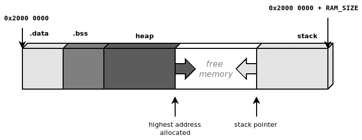
Figure 5.3 – Heap allocations and the execution stack growing in opposite directions
Collisions between two contiguous memory areas are very common and dangerous events in embedded systems with one single continuous region of memory. A solution proposed later in this chapter, in the Memory protection unit section, can be used to separate memory into two logical blocks by inserting a third inaccessible block in the middle and to help identify and intercept these cases.
Stack painting
An effective way to measure the amount of stack space needed at runtime consists of filling the estimated stack space with a well-known pattern. This mechanism, informally referred to as stack painting, reveals the maximum expansion of the execution stack at any time. By running the software with a painted stack, it is in fact possible to measure the amount of stack used by looking for the last recognizable pattern, and assuming that the stack pointer has moved during the execution, but never crossing that point.
We can perform stack painting manually in the reset handler, during memory initialization. To do so, we need to assign an area to paint. In this case, it would be the last 8 KB of memory up until _end_stack. Once again, while manipulating the stack in the reset_handler function, local variables should not be used. The reset_handler function will store the value of the current stack pointer in the sp global variable:
static unsigned int sp;
Within the handler, the following section can be added before invoking main():
asm volatile("mrs %0, msp" : "=r"(sp));
dst = ((unsigned int *)(&_end_stack)) – (8192 / sizeof(unsigned int)); ;
while (dst < sp) {
   *dst = 0xDEADC0DE;
   dst++;
}
The first assembly instruction is used to store the current value of the stack pointer to the sp variable, ensuring that the painting stops after the area is painted but only up until the last unused address in the stack:
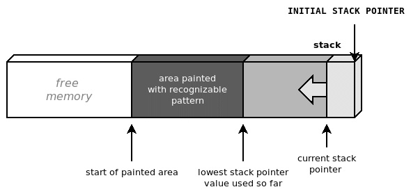
Figure 5.4 – Painting the stack area with a recognizable pattern helps to estimate the stack memory used in the prototype
The current stack usage can be checked periodically at runtime – for instance, in the main loop – to detect the area painted with the recognizable pattern. The areas that are still painted have never been used by the execution stack so far and indicate the amount of stack still available.
This mechanism may be used to verify the amount of stack space required by the application to run comfortably. According to the design, this information can be used later on to set a safe lower limit on the segment that can be used for the stack. Stack painting, however, is not always effective, as it gives a measurement of the stack used during the execution, but it might overlook corner cases where the stack usage may be bigger. Increasing test coverage while keeping an eye on the stack painting at the end of each test may help to allocate the appropriate amount of stack space during the development phase.
Heap management
Safety-critical embedded systems are often designed not to implement any dynamic memory allocation. While this may sound extreme, it minimizes the impact of the most common programming mistakes in the application code, which might lead to catastrophic consequences for the running system.
On the other hand, dynamic allocation is a powerful tool because it gives complete control over the lifetime and the size of the memory blocks. Many third-party libraries designed for embedded devices expect an existing implementation of dynamic memory allocation. Dynamic memory is managed through a heap structure in memory, by keeping track of the status and the size for each allocation, incrementing the pointer to the next area of free memory, and reusing blocks that have been freed if new allocation requests are processed.
A standard programming interface for heap allocation consists of two basic functions:
void *malloc(size_t size);
void free(void *ptr);
These function signatures are defined by the ANSI-C standard and are commonly found in operating systems. They allow us to request a new memory area of a given size and free up the previously allocated area referred to by the specified pointer respectively. More complete heap management has support for an additional call, realloc, that allows us to resize a memory area previously allocated, either in place or by relocating it to a new segment that is large enough to contain an object of the given size:
void *realloc(void *ptr, size_t size);
While realloc is generally left out from most of the embedded system implementations, it may be useful in some cases to resize objects in memory.
Depending on the implementation, memory management could be more or less efficient in joining together contiguous blocks that had been freed, in order to create larger available segments without having to allocate new space. Real-time operating systems usually offer allocators with different heap management. To mention one, FreeRTOS provides five different portable heap managers to choose from.
If we opt for a solution that allows for dynamic allocations, it is important to design it while taking into account a few important factors:
- The geometry of the regions where the heap is placed
- The higher boundary of the section dedicated to the heap, if it is shared with the stack, to prevent heap-stack collisions
- The policy to adopt if there is not enough memory to satisfy requests for new allocations
- How to deal with memory fragmentation and keep the overhead of unused blocks as small as possible
- Using separate pools to separate the memory used by specific objects and modules
- Spreading a single pool of memory across non-contiguous regions
When no allocator is available on the target – for example, if we are developing a bare-metal application from scratch – we might be required to implement an allocator that responds to the characteristics of the design. This can be done either from scratch by providing a custom implementation of the malloc/free functions or using implementations provided by the C library in use. The first approach gives complete control over the fragmentation, memory areas, and pools to be used to implement the heap, while the latter hides most of the handling while still allowing customization of the (contiguous) memory area and boundaries. In the next two sections, we will explore the two possible strategies in more detail.
Custom implementation
Unlike servers and personal computers, where memory allocations are handled using pages of a specific size, in bare-metal embedded systems, the heap is usually one or more contiguous areas of physical memory that can be divided internally using any alignment. Building heap-based memory allocation based on the malloc/free interface consists of keeping track of the requested allocations in memory. This is usually done by attaching a small header in front of each allocation to track the state and the size of the allocated section, which can be used in the free function to validate the allocated block and make it available for the next allocation. A basic implementation, providing dynamic memory starting from the first available address after the end of the .bss section, might represent each block in memory using a preamble, such as the following:
struct malloc_block {
  unsigned int signature;
  unsigned int size;
};
Two different signatures can be assigned to identify valid blocks and differentiate blocks still in use versus blocks that have already been freed:
#define SIGNATURE_IN_USE (0xAAC0FFEE)
#define SIGNATURE_FREED (0xFEEDFACE)
#define NULL (((void *)0))
The malloc function should keep track of the highest address in the heap. In this example, a static variable is used to mark the current end of the heap. This is set to the start address at the beginning and will grow every time a new block is allocated:
void *malloc(unsigned int size)
{
  static unsigned int *end_heap = 0;
  struct malloc_block *blk;
  char *ret = NULL;
  if (!end_heap) {
    end_heap = &_start_heap;
  }
The next two lines ensure that the block requested is 32-bit-aligned to optimize the access to malloc_block:
 if (((size >>2) << 2) != size)
   size = ((size >> 2) + 1) << 2;
The malloc function then first looks in the heap for a memory section that has been previously freed:
 blk = (struct malloc_block *)&_start_heap;
 while (blk < end_heap) {
   if ((blk->signature == SIGNATURE_FREED) &&
        (blk->size >= size)) {
     blk->signature = SIGNATURE_IN_USE;
     ret = ((char *)blk) + sizeof(struct malloc_block);
     return ret;
   }
   blk = ((char *)blk) + sizeof(struct malloc_block) +
       blk->size;
   }
If no available slot is found, or if none of them is large enough to satisfy the size required for the allocation, the memory is allocated at the end of the stack and the pointer is updated accordingly:
   blk = (struct malloc_block *)end_heap;
   blk->signature = SIGNATURE_IN_USE;
   blk->size = size;
   ret = ((char *)end_heap) + sizeof(struct malloc_block);
   end_heap = ret + size;
   return ret;
 }
In both cases, the address returned hides the malloc_block control structure that precedes it. The end_heap variable always points to the end of the last block allocated in the heap, but it is not an indication of the memory used, as intermediate blocks may have been freed in the meanwhile. This example free function, demonstrating a very simple case, is only performing basic checks on the block that needs to be freed and setting the signature to indicate that the block is no longer being used:
void free(void *ptr)
{
  struct malloc_block *blk = (struct malloc_block *)
        (((char *)ptr)-sizeof(struct malloc_block));
  if (!ptr)
    return;
  if (blk->signature != SIGNATURE_IN_USE)
    return;
  blk->signature = SIGNATURE_FREED;
}
Although this example is very simplistic, it aims at explaining the basic functionality of heap allocation without taking into account all real-life constraints and limitations. In fact, allocating and freeing objects of different sizes may cause fragmentation. To minimize the impact of this phenomenon in terms of memory usage and wasted space between active allocations, the free function should at least implement some kind of mechanism to join together adjacent areas that are no longer in play. Furthermore, the preceding example, malloc, assumes that the heap section does not have an upper boundary, does not perform any check on the new location of the end_heap pointer, and does not define a strategy when there is no memory available to allocate.
Although toolchains and libraries often provide a default implementation of malloc and free, implementing custom heap-based allocation mechanisms still makes sense in cases where the implementations available do not meet the requirements – for example, if we want to manage separate memory pools or merge separate physical memory sections to use them in the same pool.
Fragmentation issues cannot be completely resolved on systems with physical memory mapping because it is impossible to move around previously allocated blocks to optimize the space available. The issue can, however, be mitigated by keeping the number of allocations under control, reusing allocated blocks as much as possible, and avoiding frequent calls to malloc/free, especially to request blocks with different sizes.
The use of dynamic memory, regardless of the implementation, introduces a number of safety concerns and should be avoided in all life-critical systems, and in general wherever it is not required. Simpler, single-purpose embedded systems can be designed to avoid the use of dynamic memory allocations altogether. In these cases, a simple malloc interface can be provided to allow permanent allocations during startup.
Using newlib
Toolchains may provide a set of utilities, which often include dynamic memory allocation mechanisms. GCC-based toolchains for microcontrollers include a reduced set of standard C calls, usually in the built-in standard C library. A popular choice, often included in the ARM-GCC embedded toolchain, is newlib. While providing the implementation of many standard calls, newlib remains as flexible as possible by allowing customization of the operations involving the hardware. The newlib library can be integrated into both single-thread, bare-metal applications and in a real-time operating system, provided that the required system calls are implemented.
In the case of malloc, newlib requires an existing implementation of the sbrk function. This function is expected to move the heap pointer forward every time a new allocation requires an extension of the heap space and return the old value of the heap to malloc, in order to complete allocations every time an existing, previously freed, and reusable block is not found in the pool:
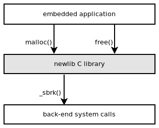
Figure 5.5 – newlib implements malloc and free and relies on an existing implementation of _sbrk
A possible implementation of the _sbrk function may be the following:
void * _sbrk(unsigned int incr)
{
  static unsigned char *heap = NULL;
  void *old_heap = heap;
  if (((incr & 0x03) != incr)
    incr = ((incr >> 2) + 1) << 2;
  if (old_heap == NULL)
    old_heap = heap = (unsigned char *)&_start_heap;
  heap += incr;
  return old_heap;
}
If the code is linked without the -nostdlib flag, the malloc and free functions, if invoked anywhere in the code, will be automatically found within the newlib library built in the toolchain and included in the final binary. Failing to define an _sbrk symbol, in this case, will result in a linking error.
Limiting the heap
In all the allocation functions seen so far, there is no limit imposed by the software on the amount of memory reserved for the heap. While overflowing the stack is often hard to prevent, and extremely difficult to recover from, running out of available heap memory can more often be gracefully handled by the application – for example, by canceling or postponing the operation that required the allocation. In more complex multithreaded systems, an operating system could actively react to the memory shortage by terminating non-vital processes to free up memory for new allocations. Some advanced systems using page-swapping mechanisms, such as Linux, may implement overcommit on the available memory. This mechanism guarantees that memory allocations never fail, and malloc will never return NULL to indicate a failure.
Memory-consuming processes in a system may be instead terminated at any time by a kernel thread, the out-of-memory killer, to make space for new allocations from other less resource-consuming processes. On an embedded system, especially if there is no multithreading, the best choice is to have the allocator return NULL when there is no physical space left on the heap so that the system can keep running and the application can possibly recover by recognizing the out-of-memory episode. The section in memory dedicated to the heap can be limited by exporting the address for its upper boundary in the linker script, as shown here:
_heap_end = ORIGIN(RAM) + LENGTH(RAM);
The backend for the newlib library malloc implementation can account for the newly introduced upper bound in the _sbrk() function:
void * _sbrk(unsigned int incr) {
  static unsigned char *heap = NULL;
  void *old_heap = heap;
  if (((incr & 0x03) != incr)
    incr = ((incr >> 2) + 1) << 2;
  if (old_heap == NULL)
    old_heap = heap = (unsigned char *)&_start_heap;
  if ((heap + incr) >= &_end_heap)
    return (void *)(-1);
  else
    heap += incr;
  return old_heap;
}
The special (void *)(-1) value that is returned by sbrk in case of memory shortage for heap allocation indicates to the calling malloc that there is not enough space to perform the requested allocation. malloc will then return NULL to the caller.
It is very important in this case that the caller always checks the return value at each invocation of malloc() and that the application logic is able to correctly detect that the system is out of memory, and react in an attempt to recover from it.
Multiple memory pools
In some systems, it is useful to keep separate sections as dynamic memory heaps, each dedicated to a specific function in the system. Heap allocation mechanisms using separate pools may be implemented for different reasons, such as ensuring that specific modules or subsystems do not use more memory than the amount that is assigned to them at compile time, or ensuring that allocations with the same size can reuse the same physical space in memory, reducing the impact of fragmentation, or even assigning a pre-defined, fixed area in memory for DMA operations with peripherals or network devices. It is possible to delimit the sections for the different pools by, as usual, exporting symbols in the linker script. The following example pre-allocates the space in memory for two pools, of 8 KB and 4 KB respectively, located at the end of the .bss section in RAM:
PROVIDE(_start_pool0 = _end_bss);
PROVIDE(_end_pool0 = _start_pool0 + 8KB);
PROVIDE(_start_pool1 = _end_pool0);
PROVIDE(_end_pool1 = _start_pool1 + 4KB);
A custom allocation function must be defined, since the malloc interface does not support the selector of the pool, but the functions can be made generic for both pools. A global structure can be populated with the values exported by the linker:
struct memory_pool {
  void *start;
  void *end;
  void *cur;
};
static struct memory_pool mem_pool[2] = {
  {
    .start = &_start_pool0;
    .end = &_end_pool0;
  },
  {
    .start = &_start_pool1;
    .end = &_end_pool1;
  },
};
The function must take an extra argument to specify the pool. Then, the allocation is performed with the same algorithm, only changing the current pointer and the boundaries of the selected pool. In this version, the out-of-memory errors are detected before moving the current heap value forward, returning NULL to notify the caller:
void *mempool_alloc(int pool, unsigned int size)
{
  struct malloc_block *blk;
  struct memory_pool *mp;
  char *ret = NULL;
  if (pool != 0 && pool != 1)
    return NULL;
  mp = mem_pool[pool];
  if (!mp->cur)
    mp->cur = mp->start;
  if (((size >>2) << 2) != size)
    size = ((size >> 2) + 1) << 2;
  blk = (struct malloc_block *)mp->start;
  while (blk < mp->cur) {
    if ((blk->signature == SIGNATURE_FREED) &&
          (blk->size >= size)) {
      blk->signature = SIGNATURE_IN_USE;
      ret = ((char *)blk) + sizeof(struct malloc_block);
      return ret;
    }
    blk = ((char *)blk) + sizeof(struct malloc_block) +
           blk->size;
  }
  blk = (struct malloc_block *)mp->cur;
  if (mp->cur + size >= mp->end)
    return NULL;
  blk->signature = SIGNATURE_IN_USE;
  blk->size = size;
  ret = ((char *)mp->cur) + sizeof(struct malloc_block);
  mp->cur = ret + size;
  return ret;
}
Once again, this mechanism does not account for memory fragmentation, so the mempool_free function can have the same implementation as free for the simplified malloc, as the only necessary thing to do is to mark the blocks being freed as unused.
In more complete cases, where free or a separate garbage collector routine takes care of merging contiguous freed blocks, it might be required to keep track of the freed blocks in each pool, in a list, or in another data structure that can be visited to check whether merging is possible.
Common heap usage errors
The use of dynamic memory allocation is considered unsafe in some environments, as it is widely known to be the source of nasty bugs, which are in general both critical and very hard to identify and fix. Dynamic allocations may be difficult to track, especially when code grows in size and complexity and there are many dynamically allocated data structures. This is already very serious in multithreaded environments, where it is still possible to implement fallback mechanisms, such as terminating a misbehaving application, but it becomes critical on single-threaded embedded systems, where these kinds of errors are often fatal for the system. The most common types of errors when programming with heap allocations are as follows:
- NULL pointer de-reference
- Double free
- Use after free
- Failure to call free, resulting in memory leaks
Some of these can be avoided by following a few simple rules. malloc returns the value that should always be checked before using the pointer. This is particularly important in environments where resources are limited, and the allocator can return NULL pointers to indicate that there is no memory available for the allocation. The preferred approach is ensuring that there is a defined strategy to follow when the required memory is not available. In any case, all dynamic pointers must be checked to ensure that they do not point to a NULL value before attempting to de-reference.
Freeing NULL pointers is a legal operation that must be identified when free is called. By including a check at the beginning of the function, if the pointer is NULL, no action is performed and the call is ignored.
Immediately after, we can also check that the memory has not been freed before. In our free function, we implement a simple check against the signature of the malloc_block structure in memory. It would be possible to add a log message, or even a breakpoint, to debug the origin of the second free function:
if (blk->signature != SIGNATURE_IN_USE) {
  /* Double free detected! */
  asm("BKPT #0") ;
  return;
}
Unfortunately, this mechanism may only work in some cases. In fact, if the block that was previously freed is assigned again by the allocator, it would be impossible to detect further uses of its original reference, and a second free would cause the second reference to be lost as well. For the same reason, use-after-free errors are hard to diagnose, as there is no way to tell that a freed memory block has been accessed again. It is possible to paint freed blocks with a recognizable pattern so that if the content of the block is altered after free has been called, the next invocation of malloc on that block can detect the alteration. However, this again does not guarantee detection of all the cases and only works for write accesses to a freed pointer; additionally, this would not be able to identify all the cases where freed memory is accessed for reading.
Memory leaks are easy to diagnose but sometimes difficult to locate. With limited resources, it is often the case that forgetting to free allocated memory uses up all the available heap very quickly. While there are techniques used to track down allocations, it is often sufficient to break into the software with the debugger and look for repeated allocations of the same size to track down the buggy caller.
In conclusion, due to their catastrophic and hideous nature, dynamic memory bugs may be one of the biggest challenges on embedded systems. Therefore, writing safer application code is often less expensive in terms of resources than hunting for memory bugs at the system level – for example, instrumenting the allocator. Analyzing the lifetime of each allocated object thoroughly, and making the logic as clear and readable as possible, can prevent most of the problems related to pointer handling and save a lot of time that would otherwise be spent debugging.
The memory protection unit
In a system without virtual address mapping, it is harder to create a separation between sections that can be accessed by the software at runtime. The memory protection unit, often referred to as the MPU, is an optional component present in many ARM-based microcontrollers. The MPU is used to separate sections in memory by setting local permissions and attributes. This mechanism has several uses in real-life scenarios, such as preventing access to memory when the CPU is running in user mode, or preventing fetching code from being executed from writable locations in RAM. When the MPU is enabled, it enforces the rules by triggering a memory exception interrupt when those rules are violated.
While commonly used by operating systems to create process stack separation and enforce privileged access to system memory, the MPU can be useful in a number of other cases, including bare-metal applications.
MPU configuration registers
In the Cortex-M, the control block region related to MPU configuration is located in the system control block, starting at address 0xE000ED90. Five registers are used to access the MPU:
- The MPU Type Register (offset 0x00) contains information about the availability of the MPU system and the number of regions supported. This register is also available on systems without an MPU to indicate that the functionality is not supported.
- The MPU Control Register (offset 0x04) is used to activate the MPU system and enable the default background mapping for all the regions that are not explicitly mapped in the MPU. If background mapping is not enabled, accessing non-mapped regions is not allowed.
- The MPU Region Number Register (RNR offset 0x08) is used to select the region to configure.
- The MPU Region Base Address Register (RBAR offset 0x0C) can be accessed to change the base address of the selected region.
- The MPU Region Attribute and Size Register (RASR offset 0x10) defines the permissions, attributes, and size of the selected region.
Programming the MPU
The MPU of Cortex-M microcontrollers supports up to eight different programmable regions. A function that enables the MPU and sets up all the regions can be implemented and invoked at the beginning of program. The MPU registers are mapped in HAL libraries, but in this case, we are going to define our own version and access them directly:
#define MPU_BASE 0xE000ED90
#define MPU_TYPE (*(volatile uint32_t *)(MPU_BASE + 0x00))
#define MPU_CTRL (*(volatile uint32_t *)(MPU_BASE + 0x04))
#define MPU_RNR (*(volatile uint32_t *)(MPU_BASE + 0x08))
#define MPU_RBAR (*(volatile uint32_t *)(MPU_BASE + 0x0c))
#define MPU_RASR (*(volatile uint32_t *)(MPU_BASE + 0x10))
In our example, we used the following defined bit-field value definitions to set the right attributes in RASR:
#define RASR_ENABLED (1)
#define RASR_RW (1 << 24)
#define RASR_RDONLY (5 << 24)
#define RASR_NOACCESS (0 << 24)
#define RASR_SCB (7 << 16)
#define RASR_SB (5 << 16)
#define RASR_NOEXEC (1 << 28)
The possible sizes, which should end up in the size field of RASR in bits 1:5, are coded as follows:
#define MPUSIZE_1K (0x09 << 1)
#define MPUSIZE_2K (0x0a << 1)
#define MPUSIZE_4K (0x0b << 1)
#define MPUSIZE_8K (0x0c << 1)
#define MPUSIZE_16K (0x0d << 1)
#define MPUSIZE_32K (0x0e << 1)
#define MPUSIZE_64K (0x0f << 1)
#define MPUSIZE_128K (0x10 << 1)
#define MPUSIZE_256K (0x11 << 1)
#define MPUSIZE_512K (0x12 << 1)
#define MPUSIZE_1M (0x13 << 1)
#define MPUSIZE_2M (0x14 << 1)
#define MPUSIZE_4M (0x15 << 1)
#define MPUSIZE_8M (0x16 << 1)
#define MPUSIZE_16M (0x17 << 1)
#define MPUSIZE_32M (0x18 << 1)
#define MPUSIZE_64M (0x19 << 1)
#define MPUSIZE_128M (0x1a << 1)
#define MPUSIZE_256M (0x1b << 1)
#define MPUSIZE_512M (0x1c << 1)
#define MPUSIZE_1G (0x1d << 1)
#define MPUSIZE_2G (0x1e << 1)
#define MPUSIZE_4G (0x1f << 1)
The first thing to do when we enter the mpu_enable function is to ensure that the feature is available on our target, by checking the MPU_TYPE register:
int mpu_enable(void)
{
  volatile uint32_t type;
  volatile uint32_t start;
  volatile uint32_t attr;
  type = MPU_TYPE;
  if (type == 0) {
    /* MPU not present! */
    return -1;
  }
In order to configure the MPU, we must ensure that it is disabled while we change the base addresses and the attributes of each region:
MPU_CTRL = 0;
The flash region that contains the executable code can be marked as read-only region 0. The values for the RASR attributes are as follows:
  start = 0;
  attr = RASR_ENABLED | MPUSIZE_256K | RASR_SCB |
       RASR_RDONLY;
  mpu_set_region(0, start, attr);
The whole RAM region can be mapped as read-write. If we do not need to execute code from RAM, we can set the execute-never (XN) bit in the region attributes. RAM is mapped as region 1 in this case:
  start = 0x20000000;
  attr = RASR_ENABLED | MPUSIZE_64K | RASR_SCB | RASR_RW
      | RASR_NOEXEC;
  mpu_set_region(1, start, attr);
Since memory mapping is processed in the same order as memory region numbers, we can use region 2 to create an exception within region 1. Regions with higher numbers have priority over regions with lower numbers, so exceptions can be created within an existing mapping with a lower number.
Region 2 is used to define a guard region as a lower boundary for the stack growing backward, the purpose of which is to intercept stack overflows. In fact, if at any moment the program tries to access the guard region, it triggers an exception and the operation fails. In this case, the guard region occupies 1 KB at the bottom of the stack. It has no access permissions configured in its attributes. The MPU ensures that the region is not accessible at runtime:
  start = (uint32_t)(&_end_stack) - (STACK_SIZE + 1024);
  attr = RASR_ENABLED | MPUSIZE_1K | RASR_SCB |
  RASR_NOACCESS | RASR_NOEXEC;
  mpu_set_region(2, start, attr);
Finally, we describe the system area as a read-write, non-executable, and non-cacheable area so that the program will still be able to access the system registers after the MPU has been activated again. We use region 3 for this:
  start = 0xE0000000;
  attr = RASR_ENABLED | MPUSIZE_256M | RASR_SB
  RASR_RW | RASR_NOEXEC;
  mpu_set_region(3, start, attr);
As a final step, we enable the MPU again. The MPU will allow us to define a background region, setting the default permissions for those areas that are not covered in the active region configurations. In this case, the absence of a definition for a background policy results in prohibited access to all the areas that are not explicitly mapped:
  MPU_CTRL = 1;
  return 0;
}
The helping function that sets the starting address and the attributes for the memory regions looks like the following:
static void mpu_set_region(int region, uint32_t start, uint32_t attr)
{
  MPU_RNR = region;
  MPU_RBAR = start;
  MPU_RNR = region;
  MPU_RASR = attr;
}
The value used to set attributes and sizes in MPU_RASR in this example is defined according to the structure of the register itself. MPU_RASR is a bit-field register, containing the following fields:
- Bit 0: The enable/disable region.
- Bits 1:5: The size of the partition (see the special values to assign to this field).
- Bits 16:18: Indicate whether the memory is bufferable, cacheable, and shared, respectively. Devices and system registers should be marked as non-cacheable at all times to guarantee the strict order of the transaction, as explained at the beginning of this chapter.
- Bits 24:26: Access permissions (read/write), separated for user and supervisor mode.
- Bit 28: Disable execution (the XN flag).
It is now possible to write a program that overflows the stack and see the difference in the debugger when the mpu_enable function is called and when it is not. If the MPU is available on the target, it is now able to intercept stack overflows, triggering an exception in the CPU:

Figure 5.6 – The guard region is marked as inaccessible in the MPU to prevent stack overflows
The configuration we used in this case for the MPU is very strict, not allowing access to any memory, except for the regions mapping flash and RAM. The extra 1-KB guard region ensures that we can detect stack overflows at runtime. This configuration in fact introduces an artificial separation between the two regions allocated for heap and stack areas, in a physically continuous space, by introducing a block that replicates inaccessible blocks in between. Although allocations in the heap exceeding the heap limit will not directly trigger an overflow, any memory access in the guard region will cause a memory fault.
In real applications, the MPU configuration may be more complex and even change its values at runtime. In Chapter 10, Parallel Tasks and Scheduling, for example, we will explain how the MPU can be used to isolate thread address spaces in a real-time operating system.
Summary
Memory management in an embedded system is the source of the most critical bugs, and for this reason, particular attention must be dedicated to designing and implementing the correct solutions for the platform in use and application purposes. The execution stack should be carefully placed, sized, and delimited when possible.
Systems not providing dynamic allocations are safer, but embedded systems with higher complexity benefit from dynamic allocation techniques. Programmers must be aware that errors in memory handling can be critical for a system and very difficult to spot, so extra care is required when code handles dynamically allocated pointers.
The MPU can be a vital tool to enforce access permissions and attributes on memory regions, and it can be used for several purposes. In the example shown, we implemented an MPU-based mechanism to enforce a physical boundary for the stack pointer.
In the next chapter, we will examine other common components included in modern microcontrollers. We will learn how to handle clock settings, interrupt priorities, general-purpose I/O communication, and other optional features.