
1
Introduction to Arduino
Perhaps you have seen the Arduino at a local retailer, heard about it from a friend who purchased one, or just saw a cool project on the Internet that piqued your interest. What is the Arduino? Most simply, it is an affordable, small-scale, simple computer that focuses on interaction with the outside world (Figure 1-1).
Most of the computers you are familiar with are controlled almost exclusively through the keyboard and mouse, touchscreen, or trackpad. An Arduino allows you to take information from the outside world with sensors that measure temperature, light and sound levels, or even the vibrations underneath your feet, and convert these measurements into motion, sound, light, and more.
Figure 1-1: The Arduino logo
The Arduino was originally developed by teachers to make it possible for their design students who were not engineers to create interactive objects and environments. Since the original Arduino was released in 2005, it is estimated that over 1 million have been sold. Designers, educators, engineers, hobbyists, and students have built all kinds of projects that sense and respond to the world with Arduino.
There are many versions of the Arduino, and each is designed for a specific function. Figure 1-2 shows a few of the Arduino boards.
We have written this book in the spirit of the Arduino team. We don’t assume that you already know programming or electronics—we will show you what you need to know to get up and running with the Arduino. It will help if you are good at building and tinkering, and you have a determined nature.
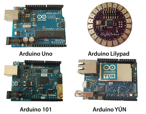
Figure 1-2: There are many versions of the Arduino, each designed for a different function.
Physical Computing
The Arduino is used for building physical computing projects. What does that mean? Physical computing refers to taking information from the world around us by using inputs such as sensors and switches and responding to that information with outputs of some kind. It could be as simple as turning on an LED when a room gets dark, or it could be a complex system of sound and light that responds to the position of a person in a room. An Arduino can act as the “brains” of this kind of a system, handling the information coming in and the response going out.
The Arduino is part of the open source hardware movement. Let’s look at what that means.
What Is Open Source Hardware?
The Arduino is defined on its website as an open source electronics prototyping platform. In the open source hardware movement, technologists share their hardware and software to foster development of new projects and ideas. Source designs are shared in a format that can be modified, and whenever possible, readily available materials and open source tools are used to create the designs.
By encouraging the sharing of resources, the open source hardware movement facilitates development of new products and designs. Open source projects emphasize the importance of documentation and sharing, making the community of users a great resource for learners.
Prototyping
The Arduino is a prototyping platform. What’s prototyping? It is building a model of a system. It can involve many phases, from initial sketches through detailed plans and a series of refinements, to building a fully functional model that can be replicated. Or it can be a quick one-off that’s put together rapidly to test an idea.
What Will I Need and Where Can I Get It?
There are several versions of the Arduino; it has been around since 2005 and is constantly evolving. For the purpose of this book, we are concerned with the Arduino Uno. Your Arduino might not look exactly like the Uno shown in Figure 1-3, because we have simplified the drawing in order to point out the sections that concern us. Since the Arduino is open source, you might also purchase a board that does not come directly from the Arduino organization. Just know that for this book we are focused on the Arduino Uno and compatible boards.

Figure 1-3: The Arduino Uno
Parts and Tools
We will also need some additional electronic parts and a few tools to build projects with the Arduino. Here is a list of the parts you will need to purchase to complete the projects in this book. We’ll give you more detail about the parts and what they do as we build each project.
Parts List
- Breadboard
- USB A-B cable
- 9-volt battery
- 9–12-volt power supply
- 9-volt battery cap or holder
- Assorted LEDs, a variety of colors
- Assorted resistors
- 10K potentiometer
- 3 momentary switches/buttons
- Photoresistor
- Speaker, 8 ohm
- 2 servo motors
- Jumper wires
The next few figures, Figure 1-4 through Figure 1-16, show you what the parts look like, along with a brief description. Electronic parts are often called components, because they are components in an electronic circuit. You’ll learn more about circuits in Chapter 3, “Meet the Circuit.”
A breadboard, shown in Figure 1-4, is used to build and test circuits quickly. A USB A-B cable, shown in Figure 1-5, connects the Arduino to a computer so you can program it. It will also provide power. A 9-volt battery, shown in Figure 1-6, can provide power when the Arduino is not attached to a computer.
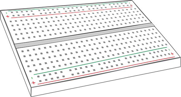
Figure 1-4: Breadboard

Figure 1-5: USB A-B cable
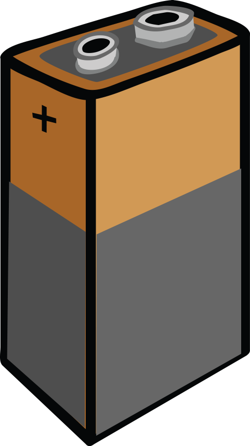
Figure 1-6: 9-volt battery

Figure 1-7: Battery cap
The battery cap, shown in Figure 1-7, will be used to attach a battery to a breadboard. The power adapter, shown in Figure 1-8, can power your Arduino when it is not attached to your computer. Light-emitting diodes (LEDs), shown in Figure 1-9, emit light when a voltage is applied.
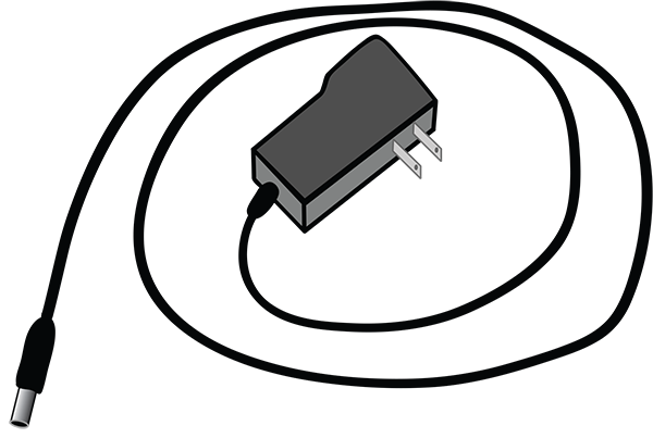
Figure 1-8: Power adapter

Figure 1-9: LEDs
Resistors, as you can see in Figure 1-10, limit the flow of current in a circuit. We will use a momentary pushbutton, shown in Figure 1-11, to make or break a connection in a circuit. Figure 1-12 shows a potentiometer, a variable resistor.

Figure 1-10: Resistors
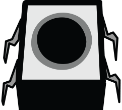
Figure 1-11: Momentary pushbutton

Figure 1-12: Potentiometer
A photoresistor, shown in Figure 1-13, changes its resistance when exposed to different levels of light. Figure 1-14 shows an 8-ohm speaker, which will play audio signals. The servo motor is an easily controlled hobby motor, as you can see in Figure 1-15. Jumper wires, shown in Figure 1-16, are used to connect components in a breadboard. You can buy them or make them yourselves with wire strippers.
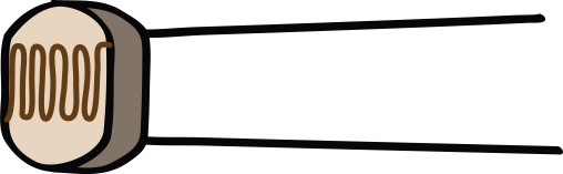
Figure 1-13: Photoresistor

Figure 1-14: Speaker, 8 ohm
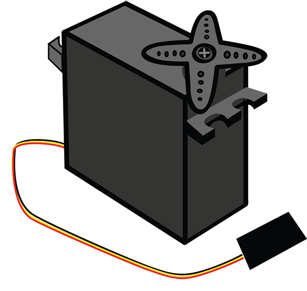
Figure 1-15: Servo motor

Figure 1-16: Jumper wires
A Note about LEDs
LEDs come in a variety of colors, styles, and sizes. We will use LEDs in many of the projects in this book because they help demonstrate a number of basic electronics and Arduino concepts in a visual way.
One important thing to remember about LEDs is that they have a polarity, or direction in which they must be placed in order to work in a project. If we place the LEDs backward, they won’t light up. How do we know the orientation of an LED?
LEDs have two legs, or leads, which are different lengths, as you can see in Figure 1-17. The longer lead is known as the anode, the side of the LED that we will connect to power. The shorter leg is called the cathode, which will be pointed away from our power source. We’ll show you how to position the leads in a circuit when we start building one, and we’ll always remind you of the polarity in later circuits.

Figure 1-17: Anode (positive lead) and cathode (negative lead) of an LED
What happens if you have a used LED that has clipped leads? In many LEDs, if you feel the bulb, one side of the rim at the bottom of the bulb feels flatter. The lead connected to that side is the cathode, or negative side.
Now let’s take a look at a few tools you will need to make these projects.
Tools
A multimeter will tell you everything you need to know about the electrical properties of a circuit, properties that are not necessarily visible to your eye. We will show you how to use it, starting in Chapter 2. The multimeter depicted in Figure 1-18 is available from SparkFun (part number TOL-12966), but you may find another one that you like. When you choose a multimeter, make sure it is digital and has removable leads, and that it is fused.

Figure 1-18: Multimeter
Needle-nose pliers, as shown in Figure 1-19, come in handy for pulling components out of the breadboard when you wish to make changes to a circuit. They are also helpful for picking up small components.
Wire strippers, pictured in Figure 1-20, are used to pull off the plastic insulating coating found on various thicknesses of wire. They will make your life a lot easier when using spools of wire, since you will be able to cut and use custom lengths of wire.
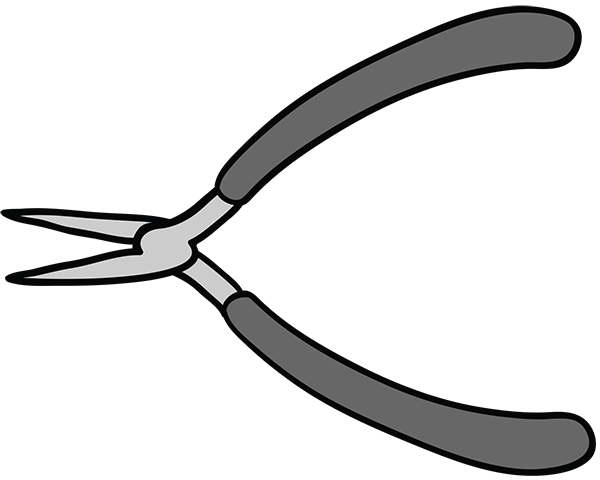
Figure 1-19: Needle-nose pliers

Figure 1-20: Wire strippers
A Word about Tools: The Soldering Iron
You may be familiar with a soldering iron and its use in electronics to connect components. In this book we have elected to use a breadboard to make connections in all the circuits listed. This means that you are not required to purchase a soldering iron or learn how to use one to complete the projects in this book.
Resources
A number of vendors sell the components that you will need. Here are the URLs of the websites of many of them, and there may be brick-and-mortar stores or other resources in your community.
Maker Shed (makershed.com)
- Selection of kits and individual Arduino components. Some electronic parts, focused on the Maker community.
SparkFun Electronics (sparkfun.com)
- Wide range of sensors and breakout boards, classic Arduinos and their homemade version.
Adafruit Industries (adafruit.com)
- Arduinos and breakout boards, sensors, electronic components.
Jameco Electronics (jameco.com)
- Mostly electronics components, endless buttons and switches.
Mouser Electronics (mouser.com)
- Some Arduino, tons of electronics, sensors, and other items.
Digi-Key Electronics (digikey.com)
- Great for ordering components, chips, and so on.
Micro Center (microcenter.com)
- A source of components and Arduinos, they have some brick-and mortar-stores as well as a website.
Kits
Kits are available from some of the vendors mentioned here that have most of the parts you will need to complete the projects. We will review exactly what you need to build the projects in every chapter. Here are a few of the kits available; you will find that there are many more.
- A kit developed by the Arduino team (arduino.cc/en/Main/ArduinoStarterKit). It can be purchased from a number of vendors.
- This kit is available from the Maker Shed: makershed.com/products/make-getting-started-with-arduino-kit-special-edition
- Adafruit Industries has a few kits, including this one: adafruit.com/products/193
Summary
This chapter set you on the path to using your Arduino. By now you know where to get the required items, you can identify various components and tools you will use, and you know something about the contributions of the open source movement.
The next chapter will look at the Arduino Uno in more detail and show you how to hook it up to your computer.