
5
Electricity and Metering
What are voltage, current, and resistance? How are they related? And why should you care?
In this chapter, you’ll learn about voltage, current, and resistance and how they interact with each other. This will help you understand how your circuits are working and how to make adjustments to them. You’ll also learn how to use the multimeter to measure these properties. This knowledge will help you debug your circuits and also get you on your way to designing and building your own projects from scratch.
Understanding Electricity
Electricity is the flow of electrons through a material, as you can see in Figure 5-1. In the projects in this book, electrons flow through carefully arranged and specified paths—through our circuits.

Figure 5-1: Electricity flows through a circuit.
Electricity has three main properties: voltage, current, and resistance. In this chapter, you’ll see how these properties interact with each other, in a fundamental relationship called Ohm’s law. You’ll also learn how placing components in different arrangements affects the electrical properties in a circuit.
Why are we looking at electrical properties, and not just building more circuits with our Arduino and other components? If you don’t understand a bit about how these properties work in a circuit, it will be very difficult to move on to building your own circuits after you’ve completed all the projects in this book. Also, without some understanding of these properties, troubleshooting your projects is next to impossible. In this chapter, you’ll learn more techniques for debugging your projects.
Measuring Electrical Properties with Your Multimeter
Remember the multimeter (Figure 5-2) from Chapter 3, “Meet the Circuit”? You learned how to set it up to test for continuity (whether your components are connected to each other). The multimeter helps you debug problems in a circuit. By testing for continuity, for example, you can verify that your circuit is a complete loop. In this chapter, you’ll learn how to use the multimeter to measure voltage, current, and resistance. Why do you need to do this? Testing voltage will help you analyze problems with your circuits; for example, is your circuit getting voltage? How much voltage is each of your components consuming?

Figure 5-2: The multimeter
If you’re going to use a multimeter to test electrical properties in a circuit, you’ll first need to build a circuit. Let’s start with a basic circuit that contains one LED, a resistor, a breadboard, and an Arduino. You won’t write an Arduino sketch this time; instead, you’ll simply use the Arduino as a power source. You’ll check the voltage coming out of the Arduino, and then test the voltage across each component. You’ll then add a second LED to the breadboard and see how the electrical properties of the components change depending on if you place them in a series or in a parallel arrangement. We’ll explain exactly what we mean by all of this shortly.
Build the Circuit Step by Step
To build the basic circuit described in this chapter, you’ll need the following parts:
- 1 red LED
- 1 220-ohm resistor (red, red, brown, gold)
- Jumper wires
- Breadboard
- Arduino Uno
- USB A-B cable
- Computer
This circuit is quite similar to the circuit you built in Chapter 4, “Programming the Arduino.” The one difference is that you aren’t powering the LED from a pin on the Arduino but from the 5-volt power bus on the breadboard.
Build!
As we said earlier, there is one major difference in this circuit, shown in Figure 5-3, from the one you built in Chapter 4: you aren’t connecting it to a digital pin on the Arduino. Instead, you’re going to get power from the power bus on the breadboard. Remember, the power bus is connected by a red jumper to the pin marked 5V (for 5 volts) on the Arduino.
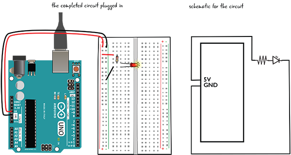
Figure 5-3: The circuit with the schematic
Before we start building, let’s take a look at the block of power and ground pins, shown in Figure 5-4. There is a pin marked 5V, and also one marked 3.3V, as well as pins marked GND for ground.
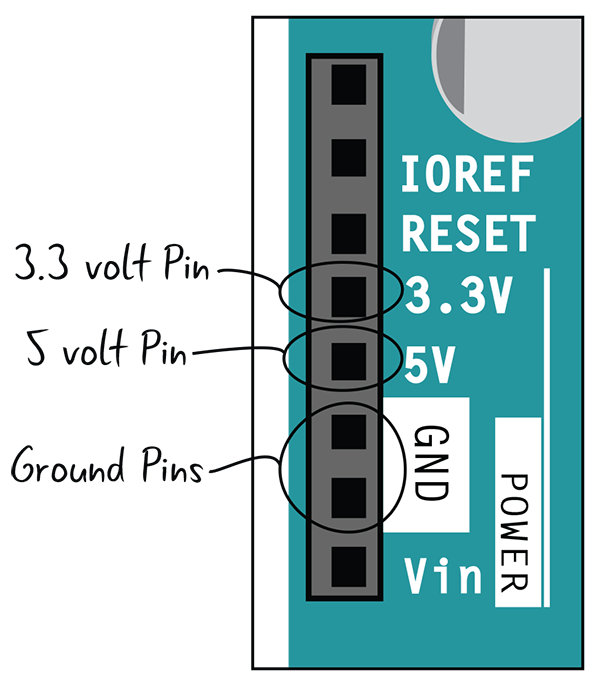
Figure 5-4: Power and ground pins on Arduino
Although we have been building our circuits using 5V, you can also use 3.3V to build some circuits with components that require less voltage. The 3.3V port works the same as the 5V except it puts out a lower amount of voltage.
Here are the steps to build the circuit, shown in Figure 5-5:
- Attach one end of a jumper to the 5V pin on the Arduino, and the other end of the jumper to the power bus on your breadboard (that’s the column marked with a red +).
- Grab another jumper and attach one end to the GND pin on the Arduino, and the other end to the ground bus on your breadboard (that’s the column marked with the green –).
- Connect a jumper from the power bus to a row of tie points.
- Connect one lead of a 220-ohm resistor to the same row of tie points. The other end goes in another row of tie points.
- Connect the anode (long leg) of the LED to the other lead of the resistor.
- Attach a jumper from the cathode (short leg) of the LED to the ground bus.
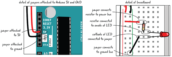
Figure 5-5: A circuit with details of power and ground pins on Arduino and the components on the breadboard
When you have the circuit built, use the USB cable to attach your Arduino to your computer. We aren’t going to write a sketch; you’re just using your computer as a power source for the Arduino.
Debugging the Circuit
If your LED lights up when you attach the USB cable to your computer, you can skip to the next page. If not, let’s troubleshoot, or “debug” the circuit.
You learned about debugging in the earlier chapters. As a reminder, it is defined as the process by which you methodically check your project to eliminate any issues that might be causing problems.
Check that power and ground are connected to the breadboard buses and the correct ports on the Arduino. Figure 5-6 shows them connected improperly.
Check that the LED is oriented correctly (anode connected to resistor that is connected to power, cathode attached to jumper that is attached to ground). Figure 5-7 shows what it should look like.

Figure 5-6: Power and ground on Arduino and breadboard improperly attached

Figure 5-7: Check the orientation of the LED.
Check the continuity; the leads of the components that are supposed to be connected need to be in the same row of tie points. Figure 5-8 shows a circuit where the components are not connected.

Figure 5-8: Components not connected
Now that you have your circuit fully functional, let’s discuss how electricity is flowing through the circuit.
Electricity: An Overview
Electricity is the flow of electrons through a material. Electricity requires a closed loop to flow from beginning to end. Your circuits create a closed loop with conductive lines and components. The electricity follows the paths of the circuit. Figure 5-9 shows the path of electricity in the circuit you just built.

Figure 5-9: Schematic with electrical flow indicated
How Does Electricity Behave?
Materials can be broken down into two different types. The first type of material is conductors, which are good at letting electricity flow. Wires are made of metal because it is a good conductive material. The second type of material is insulators, which resist the flow of electricity. Rubber is one example of an insulator.
AC and DC Current
There are two different types of electrical flow: alternating current (AC) and direct current (DC). The electricity that comes out of your wall socket is AC, whereas our Arduino and many small electronic projects and components use DC. In alternating current, represented by the drawing in Figure 5-10, the flow of electricity changes direction. In direct current there is only one direction to the flow.

Figure 5-10: Alternating current
One of the major benefits of AC is that it can be distributed over great distances, something that is much more complicated with DC. AC is also able to increase the amount of voltage supplied much more efficiently than DC. Small-scale electronics projects, such as those we create with the Arduino, do not need to transport the electricity great distances, nor do they generally require large amounts of voltage. For these reasons, our descriptions of electricity will be restricted to direct current, which we describe in more depth in the following pages. Direct current, which most small-scale electronics projects use, is represented by Figure 5-11.

Figure 5-11: Direct current
Understanding Electricity: The Water Tank Analogy
Let’s look at the three main properties of electricity: voltage, current, and resistance. We’re exploring how electricity works in DC; AC works somewhat differently, and we aren’t addressing it here. This chapter provides enough information about these properties to let you build your own Arduino projects; however, if you have a deeper interest in electronics and electrical engineering, you’ll need to know more than the simplified overview presented here.We suggest these titles: Getting Started in Electronics, by Forrest M. Mims, III (Master Publishing, Inc., 2003); Make: Electronics: Learning Through Discovery, 2nd Edition, by Charles Platt (Maker Media, 2009); and Practical Electronics for Inventors, 4th Edition, by Paul Scherz and Simon Monk (McGraw-Hill Education, 2016).

Figure 5-12: The water analogy for electricity
To help you comprehend how voltage, current, and resistance interact with one another, we’ll use a common analogy that relates electrical properties to a water system, shown in Figure 5-12. On the left, you see an electrical circuit that has a voltage source, a light bulb, and a resistor. The flow of electricity is represented by the arrows. On the right is a water system, with a pump, two tanks of water, a turbine, and pipes connecting all of the pieces. The flow of water is represented by arrows.
How do we use this analogy to understand the properties of electricity? Let’s look at voltage first. In our electrical system, we have a voltage source: a battery. What is this analogous to in our water system?
Voltage: The Potential
In our water system, water has a potential to fall from the upper tank, moving through the turbine to the lower tank. When the water gets to the lower tank, it has no more potential to fall (because it’s already at the lowest point in the system). If we increase the amount of water in the upper tank, we increase the pressure, or the potential for the water to fall. If there is increased water pressure, the turbine will turn faster, producing more work. If we decrease the amount of water in the tank, there is less pressure or potential to fall and so the turbine will turn more slowly, doing less work (Figure 5-13).

Figure 5-13: Voltage in the water analogy

How does this relate to voltage? In our electrical system, the electrons have the potential—that is, they have the pressure to flow from an area of higher charge to lower charge. Similar to more water making the turbine spin faster, in a circuit, a higher voltage source makes the light shine brighter (more electrical potential), whereas a lower voltage source (less electrical potential) makes the light dimmer, as shown in Figure 5-14. This potential is also known as the electromotive force.
Similar to the way water always flows downhill (from a higher point to a lower one), electricity has to flow from a higher voltage point toward a lower voltage point. Measuring voltage involves measuring the difference between the pressure at any two points in the system. It is always a relative value, measuring the difference between two points. Figure 5-15 shows the schematic and the electrical model, with the flow of electricity marked from power to ground.
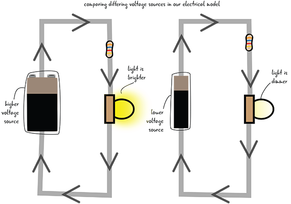
Figure 5-14: Electrical model with differing voltages

Figure 5-15: Our electrical model with the schematic
As the electricity travels through a circuit and its components, from a point of higher to lower voltage, this electric potential is consumed and used up by the components it flows through until there is no more potential energy. This zero point, measured at zero volts, is also known as the electrical ground. It is analogous to the lower tank in the water circuit, the lowest point in the system, where the water can’t fall any lower—it has no more potential to fall. This is the same ground that we’ve talked about in our circuit diagrams and on our Arduino.
What’s the Voltage Value for an Arduino?
You may be familiar with voltage as appliances, electronics, and electrical components all often list a voltage rating. Most small-scale electronics, like phone chargers, use between 3 and 12 volts DC.
Our Arduino operates at 5 volts. Remember how you connected the breadboard to the pin marked 5V on the Arduino? When your Arduino is plugged into your computer, it is getting 5 volts from the computer. In your circuits, the components (the LED, for example) use up some of the voltage. The resistors you’ve used in your circuits allow you to change (reduce) the value of the voltage, which you’ll learn more about later in this chapter.
Now that you’re familiar with voltage, let’s see how you measure it with a multimeter.
Checking the Voltage
Why measure voltage? It is critical to know that your breadboard and components are receiving voltage; this is always one of the first steps to take in debugging your electronics projects.
We are continuing to use our multimeter from SparkFun (SparkFun part number TOL-12966). Back in Chapter 3, you saw that the multimeter has probes that have to be in the correct ports to measure different electrical properties. Let’s check the probes to make sure they are in the right ports, and then set the dial on the multimeter to measure voltage.
Measuring Voltage
Make sure the black probe is in the COM (common) port and the red probe is in the port marked mAVΩ on the right side of the multimeter, as shown in Figure 5-16. Then turn the dial to the section that measures DC voltage. When measuring voltage, you need to set the dial on the meter to a value above what your estimated voltage is. For example, you know that the Arduino puts out 5 volts, so set the dial to 20V.

Figure 5-16: Settings on multimeter to measure DC voltage
We told you that 5 volts are coming out of the Arduino—let’s check with the multimeter to see if that’s true.
Grab a new jumper and stick one end of it into the power bus on the breadboard. The other end should not be connected to anything. Then connect a different spare jumper to the ground bus, with the other end loose. Don’t let the “loose” ends of the jumpers touch each other, or you will cause a short circuit, where the path of electricity takes a shortcut to ground and potentially damages your Arduino. You can reduce the chance of a short circuit by keeping space between your two leads.
Next, touch the metal end of the jumper that’s attached to the power bus with the red probe, and touch the metal end of the jumper attached to the ground bus with the black probe, as shown in Figure 5-17.
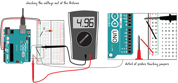
Figure 5-17: Metering the voltage on the breadboard from the Arduino
On the multimeter’s screen, you should see the number 5, though that number may be a bit lower. Our meter read 4.96. This is the amount of voltage that comes out of the Arduino and that is going into the breadboard. The slight difference has to do with the resistance in the breadboard, the components, and/or the Arduino’s internal circuitry.
What if your screen shows a negative number? That means you probably have the probes reversed; the red probe touching the jumper attached to the ground bus and the black probe attached to the power bus. Try switching the probes to the opposite jumpers and you should get a positive number.
If you see the number 1, it means that the dial on your multimeter is set to the incorrect value. Simply increase the value of the voltage dial to the next level by turning it clockwise. Then you should see an accurate value.
After you have measured the voltage, remove the jumpers (you don’t want to cause a short circuit by letting them touch each other accidentally). We’re going to measure the voltage across the components in the circuit.
Checking Voltage across the Components
Now you’ll measure the voltage across the resistor and across the LED. Doing so will show you how much voltage each component is “using up.”
Keep the dial of the meter at the spot marked 20VDC. Your Arduino should still be attached to your computer to give your Arduino power. Touch the red probe to the end of the resistor attached to the jumper to the power bus, and the black probe to the other end, as shown in Figure 5-18. What do you see on the multimeter’s display?
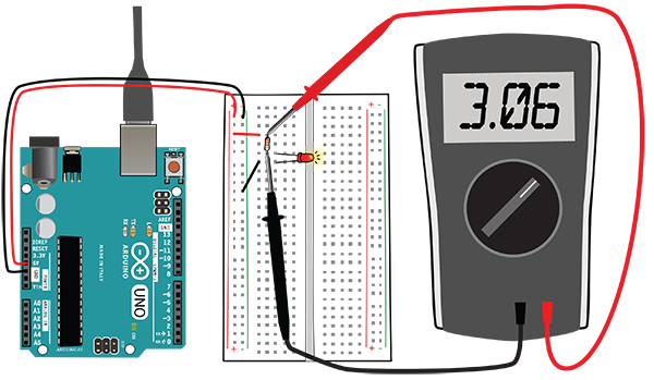
Figure 5-18: Measuring the voltage across the resistor
Now touch the anode of the LED with the red probe and the cathode with the black probe to see how much voltage is being consumed by the LED. Figure 5-19 shows a detail of the probes of the multimeter attached across the resistor and across the leads of the LED.

Figure 5-19: Details of measuring voltage in the circuit
The display on the meter should read something like 3.06 for the resistor and 1.86 for a red LED. These numbers will also vary, partially based on what color LED you’re using. Don’t worry that this doesn’t add up exactly to 5 volts. The number displayed on the meter is the amount of voltage that the LED is using. When we measure voltage across a component like this, it is called measuring the voltage drop. Voltage drop is the amount of voltage consumed by a component.
Voltage Drop
If voltage drop is the amount of voltage consumed by a component, what does this mean for our circuits? Each of our components will consume some of the voltage provided by our power source, until all of the voltage is consumed, as shown in Figure 5-20. If we only have one component (say, if we just placed our LED in without our resistor), then all of the voltage would flow through the one component and burn out our LED. How do we determine the amount of voltage a component consumes without damaging the component? Remember data sheets, which we discussed in Chapter 2, “Your Arduino”? They will have this information. We’ve already shown you how to measure this voltage drop, but later in this chapter we’ll also cover how to calculate the value ahead of time.
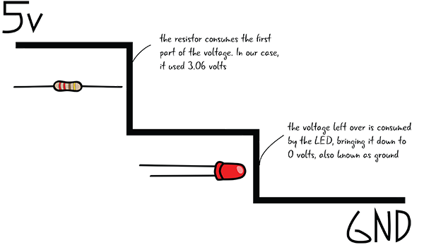
Figure 5-20: Visualizing the voltage drop
Now that you know what voltage is and how to measure it in a circuit, let’s go back to the water analogy and look at current.
Current: The Flow

In our water model, shown in Figure 5-21, we can measure the amount of water that flows through the pipes. If we measure a cross section of one of the pipes at any point, we can figure out how much water passes through it in a given amount of time—for example, we might measure 1 gallon per second. People typically refer to this as the water’s current—the more water that is flowing in a given amount of time, the stronger the current.

Figure 5-21: Current in the water analogy
The word current means pretty much the same thing in a circuit. Current is the amount of electrical charge passing through the circuit per second. Current is measured in amperes (a.k.a. amps), which is why current is also called amperage. Current requires a complete, closed loop in order to flow. If your circuit is not a complete closed loop (say there is a broken wire in the circuit), then there is zero current. Current in the electrical model is shown in Figure 5-22.
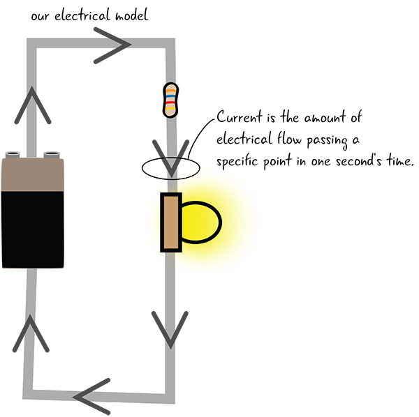
Figure 5-22: Current in the electrical model
Current in the Circuit
The amount of current in your circuit is determined by two things:
The Resistance of Your Components in the Circuit
- Components that require more current will typically have less resistance. We’ll explain more about resistance later this chapter.
The Power Supply’s Current Rating
- This rating indicates the maximum amount of current the power supply can produce. You can check the rating for current (as well as voltage) by looking at the output rating generally placed on the bottom of the power supply with other information. Figure 5-23 shows the output rating on the bottom of a power supply. (We recommended that you purchase a power supply that is rated 500 milliamps to 1 amp for current, 9–12V for voltage).

Figure 5-23: Output ratings on the bottom of a power supply
All components have a current rating shown on their case or listed on their data sheet, which shows how much flow they can handle. A component can’t force a power supply to push more current than the power supply is rated for.
What’s the Current Limit for an Arduino?
The Arduino board has a current input limit of one amp. We recommended that you purchase a power supply that is rated from 500 milliamps (½ amp) to 1000 milliamps (1 amp). The USB cord connecting your Arduino to a computer will provide 500 milliamps (½ amp), which is enough to run the Arduino board and provide power to the pins. A power supply with a higher rating than one amp could damage your Arduino.
The Arduino can only output 40 milliamps on each I/O pin. There are other electronics components that can help your Arduino cover higher current applications, but 40 milliamps is enough to power the components we’ll cover in this book.
Now, let’s look at how current can be measured with a multimeter.
Measuring Current
Measuring current is trickier than measuring voltage, and it’s done much less frequently as part of the debugging process than measuring voltage. So why are we showing you? It’s a useful exercise to learn how current flows through your circuit, and to understand the difference between voltage and current. The multimeter is your primary debugging tool, so we want you to know how to use it to check many electrical properties.
To measure current, you have to pull out one of the leads of a component in a circuit, as shown in Figure 5-24, to insert your meter and make it part of the loop of the circuit. In your circuit, you’ll pull out the anode of the LED. As always, when you are making adjustments to your circuit, make sure it is not attached to power.

Figure 5-24: Pull out the anode of the LED to prepare your board for measuring current.
Adjusting the Multimeter
You need to move the dial of the multimeter to measure 200 milliamps of DC amperage. Just like when you measure voltage, with current measurement you want to pick a value greater than what you expect the value to be—200 milliamps is the maximum safe current value for your multimeter without moving the probes (more on that later). Since you aren’t using any high-current components like motors, you can feel confident that 200 milliamps will be more than the current value. So, leave the multimeter’s probes plugged into the same ports, as shown in Figure 5-25.

Figure 5-25: Settings on the multimeter for measuring small amounts of current
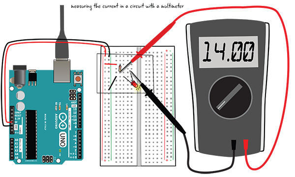
Figure 5-26: Probes touching one end of the resistor; the anode of LED pulled out of the tie point
Now that you’ve set up your multimeter correctly and arranged your circuit so that the anode of the LED is pulled out from the row of tie points, you can plug the Arduino back into your USB cord. Next, take the red probe of your meter and touch the lead of the resistor that was in the same row of tie points as the anode of the LED (before you pulled the anode out for this exercise), and touch the black probe to the anode of the LED, as shown in Figures 5-26 and 5-27. The LED should light up because the multimeter is now a part of the closed loop of your circuit. Since the multimeter is inserted in the circuit, it displays the current (a.k.a. amperage). On our meter, it read 14 milliamps. It might read something slightly different on your meter, depending partially on the color of the LED.

Figure 5-27: Detail of probe placement measuring current
As long as you’re measuring relatively small amounts of current like the 14 milliamps you measured in your circuit, it’s fine to have the red probe plugged into the multimeter’s mAVΩ port (milliamps, voltage, and resistance measurements). However, if you’re working with stronger currents (over 200 milliamps), you need to do two things to avoid frying your multimeter:
- Set the multimeter’s dial to 10A.
- Move the red probe from the mAVΩ port to the 10A port.
If you forget to do these two things, the extra current can damage your meter. We recommend that you don’t measure values of current higher than 200 milliamps.
It is a good idea to keep the red probe in the mAVΩ port—that is the correct port to use for measuring most of the electrical properties.
Resistance: Restricting the Flow
Let’s look at how resistance might be demonstrated with the water analogy in Figure 5-28. If the pipes are wider in our water system, more water can flow through them. If the pipes are narrower, less water can flow. You could say that the amount of resistance, or the restriction of flow, is greater in the narrower pipes. Where there is more resistance in the system with the narrower pipes, the turbine would turn more slowly and do less work.

Figure 5-28: Resistance in the water model
In a circuit, resistors are equivalent to narrow pipes because they restrict the flow of electrons. In the electrical system diagrams in Figure 5-29, the image on the left has only one resistor and so the light shines brightly. There are three resistors on the right image, which causes more resistance value and makes the light shine less brightly.

Resistance is measured in ohms, represented by the omega symbol shown to the left. We’ll look at how ohms are related to the other electrical properties later in this chapter, but at the moment just know that a resistor has a value that indicates how well it opposes the flow of electricity.

Figure 5-29: Resistance in the electrical model
Resistors Up Close
As you’ve seen throughout the chapter, the voltage and current within your circuits vary based on what components make up the circuit. Electronic components can be very sensitive to spikes in electricity. Also, if you have a voltage source that is too powerful for a component, it could damage the component. How can you protect your electronic components within circuits? The answer is resistors. Figure 5-30 shows a package of 220-ohm resistors. You’ve already been using resistors to protect your LEDs from the 5V power coming from the Arduino.

Figure 5-30: A package of resistors
If resistance is a property of all electronic components, why do we need a special resistor component? Resistors are great because they come in a wide range of different values and can help control the flow of electricity in a circuit. You’ve already used circuits that require 220-ohm resistors, but circuits throughout the book will need resistors with different values. How will you be able to identify how much resistance any given resistor has? There are a couple of ways. Let’s look at measuring resistance with a multimeter.
Measuring Resistance with a Multimeter
You measure resistance in a resistor outside of a circuit. This is different from what you’ve seen when measuring voltage or current, where you measured these values within a circuit. Now you’re going to measure your 220-ohm resistor.
On your multimeter, the black probe should be in the COM port, and the red probe should be in the port marked mAVΩ.
Move the dial so it is in the section that measures resistance. You’ll set the dial to 2KΩ for this example. The correct configuration is shown in Figure 5-31.

Figure 5-31: Multimeter settings to measure resistance
You learned about setting the range when you were measuring voltage. You need to set the range when you’re measuring resistance as well. You know your resistor is 220 ohms, so you must set the dial to a value that is greater than that—the 200 ohms setting will be too low. Move the dial to 2kΩ; you’re looking for a value between 200 ohms and 2000 (2k) ohms. Now that you’ve set the dial and you know the probes are in the right place, you’re ready to measure your resistor.
Touch one probe from the multimeter to each of the metal legs of the resistor, as shown in Figure 5-32. When you’re measuring resistance, it doesn’t matter what side each probe is on. You may have to hold the resistor’s leads so that they have a solid contact point with the probes, or you can set the resistor flat on a table. What value does your multimeter display? The display should show something close to .221, which is measured in kilo-ohms. Remember, since the meter is set to measure 2k ohms, or 2000 ohms, .221k ohms is actually equal to 221 ohms.
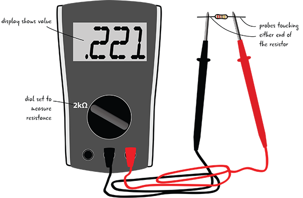
Figure 5-32: Measuring resistance with the multimeter
The value of the resistor will be shown on the meter display. Figure 5-33 shows what it looked like on our meter.

Figure 5-33: Multimeter display showing resistance value
Why is the value slightly different from the 220 ohms the resistor is rated at? It’s because resistors have a tolerance value, which tells you the accuracy range of the resistor. The resistors you’ll deal with in Arduino projects can have actual values that are plus or minus 10 percent different from the stated value. Generally speaking, you’re working with components that aren’t sensitive enough to be bothered by these discrepancies, so you don’t need to worry about the variation.
Resistors include a set of color bands to help you identify their value and their accuracy. The appendix explains how to read these color bands.
Voltage, Current, Resistance: Review
Let’s look at our water analogy diagram one last time (Figure 5-34), then quickly review the properties you’ve just learned about, what unit each is measured in, and the symbol used to represent it.
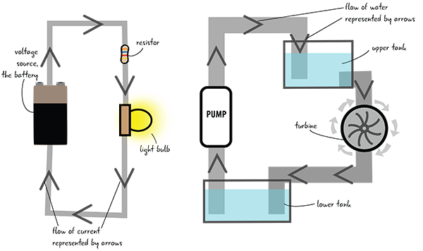
Figure 5-34: Water analogy for electricity
Table 5-1 reviews the electrical properties with their symbols and the units that they are measured in.
Table 5-1: Electrical properties
| Name | Description | Unit | Symbol |
| Voltage | Electromotive force, or the potential flow | Volt | V |
| Current | Amount of electrical flow | Ampere, or amp | A |
| Resistance | Restriction of electrical flow | Ohm | Ω |
How Does Electricity Affect Our Components?
In a circuit, current, voltage, and resistance are related. If you have current in a system, then there is necessarily a voltage and a resistance. Let’s examine what happens when you reduce only one of these properties.
Voltage

Remember that voltage represents the potential for electricity to move within a circuit. Voltage will always flow from the highest to lowest charge until it reaches the equilibrium zero state, also known as ground. If we place the same LED and resistor in our circuit, and power it using only 3.3 volts instead of the 5 volts we have been accustomed to, then our LED will be less bright. If we continue to reduce the voltage, our LED will continue to dim until it finally turns off.
Current

Current is the property related to the flow of electrons in the circuit. Current is what drives our components. What happens if we don’t have enough current within our circuit? Without enough current there are not enough electrons to turn our components on. When you have a flashlight with dead batteries, the batteries have too little current to turn the light on. If we reduce the current to our circuit by adding resistors, the LED will turn off suddenly once the minimum current needed to turn the LED on disappears.
Resistance

Resistance is a measure of how a material restricts the flow of electricity. All materials naturally have some resistance, but if the resistance is too high the electrical flow will be stopped altogether. However, if there is too little resistance our components can be overwhelmed by the amount of current and fry. We often use resistors to restrict the flow in order to preserve the other components of our circuits. If we add more resistors or change the value of the resistors in the basic circuit with the LED, we will increase resistance value and decrease the amount of electricity that reaches our LED, perhaps even limiting our LED’s ability to produce any light.
How Are Our Components Affected by a Change in Electrical Properties?
Let’s take a quick look at how our components are affected by changes in electrical properties in Table 5-2.
Table 5-2: Effects of changes in electrical properties on components
| PARt | Image | Voltage | Current | Resistance |
| LED | 
| The LED will get dimmer as the voltage gets lower, or brighter as more voltage is added; if there is too much voltage the LED will burn out. | LEDs need only a very small amount of current to run. However, reducing the amount of current too much will turn off the LED. | LEDs have a tiny amount of resistance. |
| Resistor | 
| Voltage is converted into heat when it crosses over a resistor. More voltage means more heat and less voltage means less heat. | Resistors lower the amount of current being drawn in a circuit. | The amount of resistance depends on the resistor’s rated value. Check the appendix to learn how to identify resistor values by color. |
| Battery | 
| Batteries establish the voltage level for both the high point and zero volts, a.k.a. the ground. | Current comes from the battery. The current flowing will change depending on what components are attached to the battery and how much current they require. | Since a battery is not a perfect conductor, there is a small amount of resistance inside of the battery, but when it is in our circuits it is effectively zero. |
Now let’s take a look at how voltage, current, and resistance interact with each other in a rule called Ohm’s law.
How Do Voltage, Current, and Resistance Interact? Ohm’s Law
Voltage, current, and resistance are related through a formula known as Ohm’s law. Ohm’s law, shown in Figure 5-35, states that in a given circuit, the voltage (in volts) is equal to the current (in amps) times the resistance (in ohms).

Figure 5-35: Ohm’s law
This equation shows us that, no matter how much pressure (voltage) there is, if the resistance is high the current will be restricted. This is true for all electrical wiring.
One benefit of Ohm’s law is that if we know two of the electrical properties, we can always calculate the value of the third property. You can see these relationships in Figure 5-36.

Figure 5-36: Permutations of Ohm’s law
Since you have already learned how to measure the values of voltage and current in your circuits, you can calculate the voltage, current, or resistance, as long as you know the value for two out of the three properties.
Ohm’s Law in a Circuit
Now you know about Ohm’s law, but how will it help you make your circuits? You can use Ohm’s law to determine the value of the resistors you need in your circuits. You can also use Ohm’s law as a safety check to confirm that the values of voltage and current running through are components are below the limits for those components.
For example, if you have a resistor in your circuit that has 220 ohms of resistance, and there is 20 mA (which is the same as 0.020 amps) running through the circuit, then you can use Ohm’s law to figure out how much voltage will pass through the resistor. Figure 5-37 shows the calculations.

Figure 5-37: Using Ohm’s law
Ohm’s Law Applied
How else can you use Ohm’s law? Let’s say you want to build two circuits that each contain one LED and one resistor. You’re going to power one circuit with a 3.3-volt pin on the Arduino, and another with the 5-volt pin (recall that the Arduino can provide either voltage). The LEDs we’re going to use in the circuits take 2.2 volts to light up fully, and use 25 milliamps, or 0.025 amps. Because of the voltage difference between the two circuits, you will need different resistors in each circuit to protect the LEDs. What resistor value will you need for each circuit?
Since you know that 2.2 volts are going to pass through the LED in each circuit, you can take the difference between your provided voltages (3.3 volts and 5 volts) and 2.2 volts to figure out how much voltage will pass through each resistor (Figure 5-38).

Figure 5-38: Determining voltage
Now you can use Ohm’s law to calculate how much resistance you need to have the stated voltage and a current of 0.025 amps pass through the resistor protecting your LED (Figure 5-39).

Figure 5-39: Calculating with Ohm’s law
The 5-volt circuit requires a higher value resistor than the 3.3-volt circuit. You can see that using Ohm’s law shows you how the value of the resistor required changes in your circuit based on the voltage provided. Ohm’s law is useful for making sure your components are provided with the right amount of electricity.
Arranging Components in a Circuit
How do you know how to arrange the components in your circuit? You know that the circuit must form a complete loop. Some components seem to be arranged next to each other with common electrical points, whereas others are connected end to end. What are these arrangements, and what effect do they have on the electrical properties in the circuit?
Components in Parallel and Series
Let’s look at the order of arrangement of components in a circuit. We’ll look at parallel first.
Order of Components in a Circuit: Parallel
Components in parallel are placed next to each other and share electric contact points, as shown in Figure 5-40. The electricity flows along each path through the components that are arranged in parallel.
Order of Components in a Circuit: Series
In contrast, components in series follow one after another, as shown in Figure 5-41. The circuits you have built so far have all been arranged in series—all of the electricity that flowed through the resistor then went into the LED.

Figure 5-40: Resistors arranged in parallel
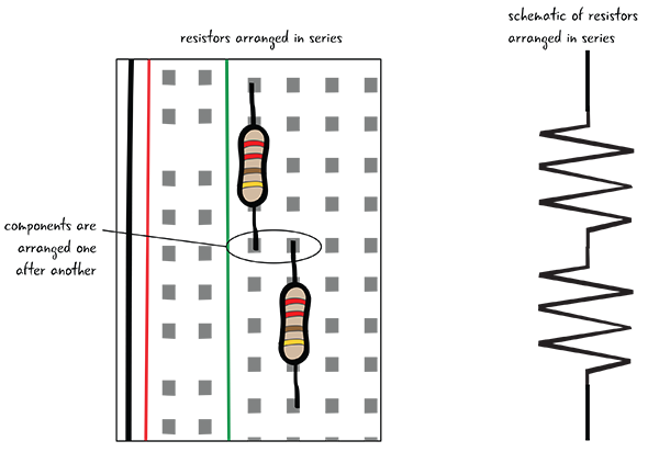
Figure 5-41: Resistors arranged in series
To see exactly what we mean by components in series and parallel, we’ll show you how to add another LED to your basic circuit, first in parallel, then in series. Then you’ll measure the voltage drop across each of the LEDs.
A Circuit with Two LEDs in Parallel
You’ll add this LED so it is in parallel with the first LED, as shown in Figure 5-42. Arranging components in parallel means that the components are connected with common electrical points. You can think of the components as being next to each other. Let’s look at the schematic for a circuit with the LEDs arranged in parallel. You can see that the resistor is attached to 5 volts and also to both of the LEDs.

Figure 5-42: Schematic for circuit with LEDs in parallel
Add a Second LED to the Circuit
To create this circuit, add a second LED to the breadboard so that the anodes of both LEDs are in one row of connected tie points and the cathodes are in a different single row of connected tie points. Both of the anodes are now connected to one end of the resistor, and both of the cathodes are connected by a jumper to ground, as shown in Figure 5-43. Remember to disconnect your computer before you make any changes to the circuit.
You’ve added the second LED, so you’re almost ready to check the voltage in this circuit.
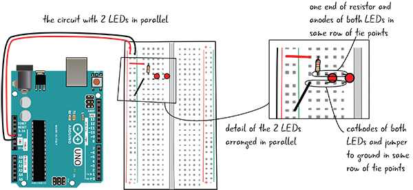
Figure 5-43: Adding the second LED in parallel
Measuring Voltage across LEDs in Parallel
When you have the LED placed correctly in the breadboard, attach your computer again to the Arduino. Next, set the dial on your multimeter to measure 20 volts. Then place the red probe on the anode of one of the LEDs, and the black probe on the cathode of the same LED, as shown in Figures 5-44 and 5-45.

Figure 5-44: Measuring voltage of a component in parallel

Figure 5-45: Measuring the voltage of LED 1 and 2
The display on your meter should read about 1.78 volts for red LEDs (if it is not exactly the same, that’s because the LEDs you’re using are rated differently than the ones you used to build the circuit). After you’ve tested the voltage across one of the LEDs, check the other, as shown in Figure 5-45. The value should be the exact same voltage drop for both LEDs if you used identical LEDs. You don’t need to measure the voltage across the resistor, because it will be the same value as you had with your basic circuit.
The Multimeter in Parallel
You may have noticed that the LEDs share common electrical contact points, and so does the multimeter. When you’re using the multimeter to measure voltage, the multimeter is in a parallel arrangement with the component whose voltage you are measuring (Figure 5-46).
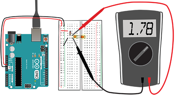
Figure 5-46: The multimeter is in parallel with the LEDs.
Components in Parallel: What Effect Does That Have on the Voltage?
You know that components in parallel share the same electrical contact points. Electricity will take all possible paths from the beginning of a circuit to its end. As you saw with our voltage measurement, the same voltage will pass through all the components in parallel (Figure 5-47).

Figure 5-47: Many LEDs in parallel
If you want several LEDs to glow the same brightness, you can place the LEDs in parallel and know that they will all receive the same voltage, unchanged by the number of LEDs in place. You aren’t able to light more than a few LEDs in parallel from your Arduino, however, since you’re limited by the amount of current provided.
Building a Two-LED Series Circuit
Now we’re going to adjust our circuit, placing the LEDs so they are in an arrangement called series. Components that are in series are placed one right after each other. It is easy to see this by looking at Figure 5-48, where two LEDs are shown one right after the other; in fact, the resistor is also in series in this arrangement. Most circuits will be a combination of components arranged in series and in parallel.

Figure 5-48: Schematic for the circuit with LEDs in series
Start by unplugging your Arduino from your computer. To place the second LED in series with the first, place the anode (long leg) of the second LED in the same row of tie points as the cathode (short leg) of the first LED. Place the cathode of the second LED in a separate row of tie points. You will have to move the jumper that goes to ground so it is in the same row of tie points as the cathode of the second LED, as shown in Figure 5-49. (Remember, the circuit has to be a complete loop in order to work.)
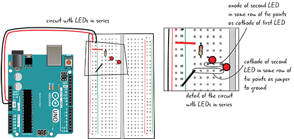
Figure 5-49: Placing the second LED in series
When you have adjusted your circuit, you will be ready to meter it.
Metering the Voltage of Components in Series
Metering components that are in series for voltage is much the same as metering components that are arranged in parallel. Plug your Arduino into your computer and the LEDs should both light up. With the dial again on 20V, place the red probe on the anode of one of the LEDs and the black probe on the cathode of the same LED, as shown in Figure 5-50. The voltage should read something like 1.77 volts. Next, measure the voltage across the other LED; your result should be similar to what you got for the first LED. Finally, measure the voltage across the resistor (for us, the value was 1.38 volts). Figure 5-51 shows a detail of metering the components in the circuit.
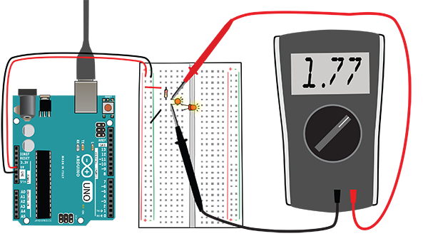
Figure 5-50: Measuring the voltage of the components in series

Figure 5-51: Details of metering the circuit
Components in Series: What Effect Does That Have on the Voltage?
In your circuit, the electricity must pass through the resistor before it gets to the first LED. As you saw in our multimeter measurements, voltage is consumed as it passes through each component. Although the voltage across each LED is about the same as for your one LED in your basic circuit, the value of the voltage across the resistor drops. The resistor consumes less voltage in this series example because two LEDs in the circuit are consuming voltage. Note that the value of the resistor does not change, but since each LED now requires its own voltage, the resistor consumes a smaller portion of the total voltage. Figure 5-52 represents the voltage drop in the circuit. The values of voltage are each adjusted according to Ohm’s law and can be measured with a multimeter.
You’ll often have to wire resistors in series with other components, like LEDs, in order to drop the value of the voltage that enters your component.
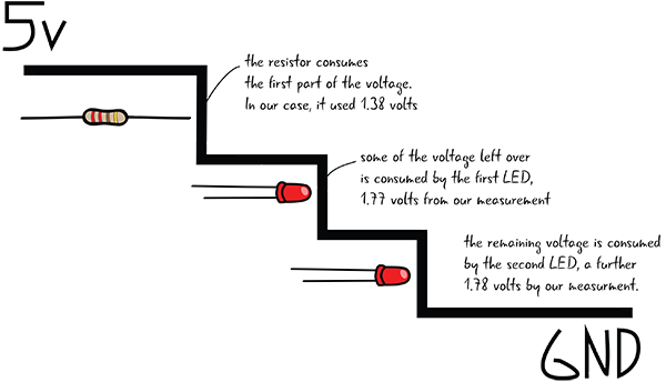
Figure 5-52: Visualizing voltage drop across the circuit with LEDs in series
It’s less likely that you’ll put multiple LEDs in series since each additional LED makes all your lights dimmer. Old strings of holiday lights, such as those in Figure 5-53, are a real-world example of lights designed to be wired in series. Being wired in series is the reason that if one bulb burns out the whole string of lights turns off. More recent string lights have been redesigned to avoid this problem.

Figure 5-53: Christmas lights, arranged in series
The Multimeter in Series
Remember how you pulled out the anode of the LED when you were measuring current in your basic circuit? Then you inserted the multimeter right into the circuit, touching one end of the resistor and the anode of the LED to complete your circuit. In that arrangement, the multimeter was in series with the resistor and the LED. The multimeter has to be in series to measure the current, because then it does not alter the value of the current (Figure 5-54).
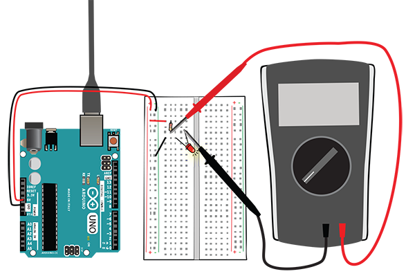
Figure 5-54: The multimeter is in series with the other components when measuring current.
Table 5-3 shows the effects of electrical properties on components in both series and parallel.
Table 5-3: Effects of electrical properties on components in series and parallel
| Effect on electrical properties | Components in series | Components in parallel |
| Effect on voltage | Each component consumes part of the voltage. | Equal voltage will cross all parallel components. |
| Effect on current | Equal current crosses all series components. | The current gets split based on the resistance value of each component. |
| Effect on resistance | Total resistance equals all values of resistance added together. | Resistance is reduced when components are in parallel. |
Summary
You’ve learned about voltage, current, and resistance and how they interact, through Ohm’s law, and you know how to measure those properties with your multimeter. You’ve also learned about setting up components in series and in parallel. In the next chapter you’ll return to Arduino projects and get additional programming practice.