Chapter 1. Create and manage virtual machines
Virtual machines (VMs) are part of the Microsoft Azure Infrastructure-as-a-Service (IaaS) offering. With VMs, you can deploy Windows Server and Linux-based workloads and have greater control over the infrastructure, your deployment topology, and configuration as compared to Platform-as-a-Service (PaaS) offerings such as Web Apps and API Apps. That means you can more easily migrate existing applications and VMs without modifying code or configuration settings, but still benefit from Azure features such as management through a centralized web-based portal, monitoring, and scaling.
Important: Have you read page xvii
It contains valuable information regarding the skills you need to pass the exam.
Skills in this chapter:
![]() Skill 1.1: Deploy workloads on Azure ARM virtual machines
Skill 1.1: Deploy workloads on Azure ARM virtual machines
![]() Skill 1.2: Perform configuration management
Skill 1.2: Perform configuration management
![]() Skill 1.4: Design and implement ARM VM storage
Skill 1.4: Design and implement ARM VM storage
![]() Skill 1.6: Manage ARM VM availability
Skill 1.6: Manage ARM VM availability
![]() Skill 1.7: Design and implement DevTest Labs
Skill 1.7: Design and implement DevTest Labs
Skill 1.1: Deploy workloads on Azure ARM virtual machines
Microsoft Azure ARM VMs can run more than just Windows and .NET applications. They provide support for running many forms of applications using various operating systems. This section describes where and how to analyze what is supported and how to deploy three different forms of VMs.
This skill covers how to:
![]() Identify supported workloads
Identify supported workloads
![]() Create a Windows Server VM
Create a Windows Server VM
![]() Create a Linux VM
Create a Linux VM
![]() Create a SQL Server VM
Create a SQL Server VM
Identify supported workloads
A workload describes the nature of a solution, including consideration such as: whether it is an application that runs on a single machine or it requires a complex topology that prescribes the operating system used, the additional software installed, the performance requirements, and the networking environment. Azure enables you to deploy a wide variety of VM workloads, including:
![]() “Bare bones” VM workloads that run various versions of Windows Client, Windows Server and Linux (such as Debian, Red Hat, SUSE and Ubuntu)
“Bare bones” VM workloads that run various versions of Windows Client, Windows Server and Linux (such as Debian, Red Hat, SUSE and Ubuntu)
![]() Web servers (such as Apache Tomcat and Jetty)
Web servers (such as Apache Tomcat and Jetty)
![]() Data science, database and big-data workloads (such as Microsoft SQL Server, Data Science Virtual Machine, IBM DB2, Teradata, Couchbase, Cloudera, and Hortonworks Data Platform)
Data science, database and big-data workloads (such as Microsoft SQL Server, Data Science Virtual Machine, IBM DB2, Teradata, Couchbase, Cloudera, and Hortonworks Data Platform)
![]() Complete application infrastructures (for example, those requiring server farms or clusters like DC/OS, SharePoint, SQL Server AlwaysOn, and SAP)
Complete application infrastructures (for example, those requiring server farms or clusters like DC/OS, SharePoint, SQL Server AlwaysOn, and SAP)
![]() Workloads that provide security and protection (such as antivirus, intrusion detection systems, firewalls, data encryption, and key management)
Workloads that provide security and protection (such as antivirus, intrusion detection systems, firewalls, data encryption, and key management)
![]() Workloads that support developer productivity (such as the Windows 10 client operating system, Visual Studio, or the Java Development Kit)
Workloads that support developer productivity (such as the Windows 10 client operating system, Visual Studio, or the Java Development Kit)
There are two approaches to identifying supported Azure workloads. The first is to determine whether the workload is already explicitly supported and offered through the Azure Marketplace, which provides a large collection of free and for-pay solutions from Microsoft and third parties that deploy to VMs. The Marketplace also offers access to the VM Depot, which provides a large collection of community provided and maintained VMs. The VM configuration and all of the required software it contains on the disk (or disks) is called a VM image. The topology that deploys the VM and any supporting infrastructure is described in an Azure Resource Manager (ARM) template that is used by the Marketplace to provision and configure the required resources.
The second approach is to compare the requirements of the workload you want to deploy directly to the published capabilities of Azure VMs or, in some cases, to perform proof of concept deployments to measure whether the requirements can be met. The following is a representative, though not exhaustive, list of the requirements you typically need to take into consideration:
![]() CPU and RAM memory requirements
CPU and RAM memory requirements
![]() Disk storage capacity requirements, in gigabytes (GBs)
Disk storage capacity requirements, in gigabytes (GBs)
![]() Disk performance requirements, usually in terms of input/output operations per second (IOPS) and data throughput (typically in megabytes per second)
Disk performance requirements, usually in terms of input/output operations per second (IOPS) and data throughput (typically in megabytes per second)
![]() Operating system compatibility
Operating system compatibility
![]() Networking requirements
Networking requirements
![]() Availability requirements
Availability requirements
![]() Security and compliance requirements
Security and compliance requirements
This section covers what is required to deploy the “bare bones” VM (that is, one that has the operating system and minimal features installed) that can serve as the basis for your more complex workloads, and describes the options for deploying a pre-built workload from the Marketplace.
Create a Windows Server VM
Fundamentally, there are two approaches to creating a new VM. You can upload a VM that you have built on-premises, or you can instantiate one from the pre-built images available in the Marketplace. This section focuses on the latter and defers coverage of the upload scenario until the next section.
To create a bare bones Windows Server VM in the portal, complete the following steps:
Navigate to the portal accessed via https://manage.windowsazure.com.
Select New on the command bar.
Within the Marketplace list, select the Compute option.
On the Compute blade, select the image for the version of Windows Server you want for your VM (such as Windows Server 2016 VM).
On the Basics blade, provide a name for your VM, the Disk Type, a User Name and Password, and choose the Subscription, Resource Group and Location into which you want to deploy (Figure 1-1).
Select OK.
On the Choose A Size Blade, select the desired tier and size for your VM (Figure 1-2).
Choose Select.
On the Settings blade, leave the settings at their defaults and select OK.
On the Purchase blade, review the summary and select Purchase to deploy the VM.


Navigate to the portal accessed via https://portal.azure.com.
Select New on the command bar.
Within the Marketplace list, select the Compute option.
On the Compute blade, select the image for the version of Ubuntu Server (Figure 1-3) you want for your VM (such as Ubuntu Server 16.04 LTS).
Select Create.
On the Basics blade, provide a name for your VM, the Disk Type, a User Name and Password (or SSH public key if preferred), and choose the Subscription, Resource Group and Location into which you want to deploy.
Select OK.
On the Choose a size blade, select the desired tier and size for your VM.
Choose select.
On the Settings blade, leave the settings at their defaults and select OK.
On the Purchase blade, review the summary and select Purchase to deploy the VM.

Create a SQL Server VM
The steps for creating a VM that has SQL Server installed on top of Windows Server are identical to those described earlier for provisioning a Windows Server VM using the portal. The primary differences surface in the fourth step: instead of selecting a Windows Server from the Marketplace list, select a SQL Server option (such as SQL Server 2016 SP1 Enterprise) and follow the prompts to complete the configuration (such as the storage configuration, patching schedule and enablement of features like SQL Authentication and R Services) of the VM with SQL Server and to deploy the VM.
Skill 1.2: Perform configuration management
A number of configuration management tools are available for provisioning, configuring, and managing your VMs. In this section, you learn how to use Windows PowerShell Desired State Configuration (DSC) and the VM Agent (via custom script extensions) to perform configuration management tasks, including automating the process of provisioning VMs, deploying applications to those VMs, and automating configuration of those applications based on the environment, such as development, test, or production.
This skill covers how to:
![]() Automate configuration management by using PowerShell Desired State Configuration (DSC) and the VM Agent (using custom script extensions)
Automate configuration management by using PowerShell Desired State Configuration (DSC) and the VM Agent (using custom script extensions)
![]() Configure VMs with Custom Script Extension
Configure VMs with Custom Script Extension
![]() Use PowerShell DSC
Use PowerShell DSC
![]() Configure VMs with DSC
Configure VMs with DSC
![]() Enable remote debugging
Enable remote debugging
Automate configuration management by using PowerShell Desired State Configuration (DSC) and the VM Agent (using custom script extensions)
Before describing the details of using PowerShell DSC and the Custom Script Extension, this section provides some background on the relationship between these tools and the relevance of the Azure Virtual Machine Agent (VM Agent) and Azure virtual machine extensions (VM extensions).
When you create a new VM in the portal, the VM Agent is installed by default. The VM Agent is a lightweight process used for bootstrapping additional tools on the VM by way of installing, configuring, and managing VM extensions. VM extensions can be added through the portal, but they are also commonly installed with Windows PowerShell cmdlets or through the Azure Cross Platform Command Line Interface (Azure CLI).
With the VM Agent installed, you can add VM extensions. Popular VM extensions include the following:
![]() PowerShell Desired State Configuration (for Windows VMs)
PowerShell Desired State Configuration (for Windows VMs)
![]() Custom Script Extension (for Windows or Linux)
Custom Script Extension (for Windows or Linux)
![]() Team Services Agent (for Windows or Linux VMs)
Team Services Agent (for Windows or Linux VMs)
![]() Microsoft Antimalware Agent (for Windows VMs)
Microsoft Antimalware Agent (for Windows VMs)
![]() Network Watcher Agent (for Windows or Linux VMs)
Network Watcher Agent (for Windows or Linux VMs)
![]() Octopus Deploy Tentacle Agent (for Windows VMs)
Octopus Deploy Tentacle Agent (for Windows VMs)
![]() Docker extension (for Linux VMs)
Docker extension (for Linux VMs)
![]() Puppet Agent (for Windows VMs)
Puppet Agent (for Windows VMs)
![]() Chef extension (for Windows or Linux)
Chef extension (for Windows or Linux)
You can add VM extensions as you create the VM through the portal, as well as run them using the Azure CLI, PowerShell and Azure Resource Manager templates.
Configure VMs with Custom Script Extension
Custom Script Extension makes it possible to automatically download files from Azure Storage and run Windows PowerShell (on Windows VMs) or Shell scripts (on Linux VMs) to copy files and otherwise configure the VM. This can be done when the VM is being created or when it is already running. You can do this from the portal or from a Windows PowerShell command line interface, the Azure CLI, or by using ARM templates.
Configuring a new VM with Custom Script Extension
Create a Windows Server VM following the steps presented in the earlier section, “Creating a Windows Server VM.” After creating the VM, complete the following steps to set up the Custom Script Extension:
Navigate to the blade for your VM in the portal accessed via https://portal.azure.com.
From the menu, scroll down to the Settings section, and select Extensions (Figure 1-4).
On the Extensions blade, select Add on the command bar.
From the New Resource blade, select Custom Script Extension (Figure 1-5).
On the Custom Script blade, select Create.
On the Install Extension blade (Figure 1-6), select the Folder button and choose the .ps1 file containing the script you want to run when the VM starts. Optionally, provide arguments. The Version of DSC is required, for example 2.21.
Select OK.


Use PowerShell DSC
PowerShell Desired State Configuration (DSC) is a management platform introduced with Windows PowerShell 4.0, available as a Windows feature on Windows Server 2012 R2. PowerShell DSC is implemented using Windows PowerShell. You can use it to configure a set of servers (or nodes) declaratively, providing a description of the desired state for each node in the system topology. You can describe which application resources to add, remove, or update based on the current state of a server node. The easy, declarative syntax simplifies configuration management tasks.
With PowerShell DSC, you can instruct a VM to self-provision to a desired state on first deployment and then have it automatically update if there is “configuration drift.” Configuration drift happens when the desired state of the node no longer matches what is described by DSC.
DSC resources
Resources are core building blocks for DSC. A script can describe the target state of one or more resources, such as a Windows feature, the Registry, the file system, and other services. For example, a DSC script can describe the following intentions:
![]() Manage server roles and Windows features
Manage server roles and Windows features
![]() Manage registry keys
Manage registry keys
![]() Copy files and folders
Copy files and folders
![]() Deploy software
Deploy software
![]() Run Windows PowerShell scripts
Run Windows PowerShell scripts
Configuration keyword
DSC extends Windows PowerShell 4.0 with a Configuration keyword used to express the desired state of one or more target nodes. For example, the following configuration indicates that a server should have IIS enabled during provisioning:
Configuration EnableIIS
{
Node WebServer
{
WindowsFeature IIS {
Ensure = "Present",
Name = "Web-Server"
}
}
}
The Configuration keyword can wrap one or more Node elements, each describing the desired configuration state of one or more resources on the node. In the preceding example, the server node is named WebServer, the contents of which indicate that the Windows Feature “IIS” should be configured, and that the Web-Server component of IIS should be confirmed present or installed if absent.

Exam Tip
After the DSC runs, a Managed Object Format (MOF) file is created, which is a standard endorsed by the Distributed Management Task Force (DTMF). See: http://www.dmtf.org/education/mof.
Custom resources
Many resources are predefined and exposed to DSC; however, you may also require extended capabilities that warrant creating a custom resource for DSC configuration. You can implement custom resources by creating a Windows PowerShell module. The module includes a MOF schema, a script module, and a module manifest.
Local Configuration Manager
Local Configuration Manager is the engine of DSC, which runs on all target nodes and enables the following scenarios for DSC:
![]() Pushing configurations to bootstrap a target node
Pushing configurations to bootstrap a target node
![]() Pulling configuration from a specified location to bootstrap or update a target node
Pulling configuration from a specified location to bootstrap or update a target node
![]() Applying the configuration defined in the MOF file to the target node, either during the bootstrapping stage or to repair configuration drift
Applying the configuration defined in the MOF file to the target node, either during the bootstrapping stage or to repair configuration drift
Local Configuration Manager runs invoke the configuration specified by your DSC configuration file. You can optionally configure Local Configuration Manager to apply new configurations only, to report differences resulting from configuration drift, or to automatically correct configuration drift.
Configure VMs with DSC
To configure a VM using DSC, first create a Windows PowerShell script that describes the desired configuration state. As discussed earlier, this involves selecting resources to configure and providing the appropriate settings. When you have a configuration script, you can use one of a number of methods to initialize a VM to run the script on startup.
Creating a configuration script
Use any text editor to create a Windows PowerShell file. Include a collection of resources to configure, for one or more nodes, in the file. If you are copying files as part of the node configuration, they should be available in the specified source path, and a target path should also be specified. For example, the following script ensures IIS is enabled and copies a single file to the default website:
configuration DeployWebPage
{
node ("localhost")
{
WindowsFeature IIS
{
Ensure = "Present"
Name = "Web-Server"
}
File WebPage
{
Ensure = "Present"
DestinationPath = "C:inetpubwwwrootindex.html"
Force = $true
Type = "File"
Contents = '<html><body><h1>Hello Web Page!</h1></body></html>'
}
}
}
Deploying a DSC configuration package
After creating your configuration script and allocating any resources it requires, you need to produce a compressed zip file containing the configuration script in the root, along with any resources needed by the script. You create the zip and copy it up to Azure Storage in one command using Publish-AzureRMVmDscConfiguration using Windows PowerShell and then apply the configuration with SetAzureRmVmDscExtension.
Assume you have the following configuration script in the file iisInstall.ps1 on your local machine:
configuration IISInstall
{
node "localhost"
{
WindowsFeature IIS
{
Ensure = "Present"
Name = "Web-Server"
}
}
}
You would then run the following PowerShell cmdlets to upload and apply the configuration:
#Load the Azure PowerShell cmdlets
Import-Module Azure
#Login to your Azure Account and select your subscription (if your account has multiple
subscriptions)
Login-AzureRmAccount
Set-AzureRmContext -SubscriptionId <YourSubscriptionId>
$resourceGroup = "dscdemogroup"
$vmName = "myVM"
$storageName = "demostorage"
#Publish the configuration script into Azure storage
Publish-AzureRmVMDscConfiguration -ConfigurationPath .iisInstall.ps1
-ResourceGroupName $resourceGroup -StorageAccountName $storageName -force
#Configure the VM to run the DSC configuration
Set-AzureRmVmDscExtension -Version 2.21
-ResourceGroupName $resourceGroup -VMName $vmName
-ArchiveStorageAccountName $storageName
-ArchiveBlobName iisInstall.ps1.zip -AutoUpdate:$true -ConfigurationName
"IISInstall"
Configuring an existing VM using the Azure Portal
Before configuring an existing VM using the Azure Portal, you will need to create a ZIP package around your PowerShell script. To do so, run the Publish-AzureVMDscConfiguration cmdlet providing the path to your PowerShell script and the name of that destination zip file to create, for example:
Publish-AzureVMDscConfiguration .iisInstall.ps1 -ConfigurationArchivePath .iisInstall.
ps1.zip
Then you can proceed in the Azure Portal. To configure an existing VM in the portal, complete the following steps:
Navigate to the blade for your VM in the portal accessed via https://portal.azure.com.
From the menu, scroll down to the Settings section, and select Extensions.
On the Extensions blade, select Add on the command bar.
From the New Resource blade, select PowerShell Desired State Configuration.
On the PowerShell Desired State Configuration blade, select Create.
On the Install Extension blade, select the folder button and choose the zip file containing the DSC configuration.
Provide the module-qualified name of the configuration in your .ps1 that you want to apply. This value is constructed from the name of your .ps1 file including the extension, a slash () and the name of the configuration as it appears within the .ps1 file. For example, if your file is iisInstall.ps1 and you have a configuration named IISInstall, you would set this to “iisInstall.ps1IISInstall”.
Optionally provide any Data PSD1 file and configuration arguments required by your script.
Specify the version of the DSC extension (Figure 1-7) you want to install (e.g., 2.21).
Select OK.

Enable remote debugging
You can use remote debugging to debug applications running on your Windows VMs. Server Explorer in Visual Studio shows your VMs in a list, and from there you can enable remote debugging and attach to a process following these steps:
In Visual Studio, open Cloud Explorer.
Expand the node of the subscription containing your VM, and then expand the Virtual Machines node.
Right-click the VM you want to debug and select Enable Debugging. Click Yes in the dialog box to confirm.
This installs a remote debugging extension to the VM so that you can debug remotely. The progress will be shown in the Microsoft Azure Activity Log. After the debugging extension is installed, you can continue.
Right-click the virtual machine again and select Attach Debugger. This presents a list of processes in the Attach To Process dialog box.
Select the processes you want to debug on the VM and click Attach. To debug a web application, select w3wp.exe, for example.
Skill 1.3: Scale ARM VMs
Similar to Azure Web Apps, Azure Virtual Machines provides the capability to scale in terms of both instance size and instance count and supports auto-scale on the instance count. However, unlike Websites that can automatically provision new instances as a part of scale out, Virtual Machines on their own must be pre-provisioned in order for auto-scale to turn instances on or off during a scaling operation. To achieve scale-out without having to perform any pre-provisioning of VM resources, Virtual Machine Scale Sets should be deployed.
This skill covers how to:
![]() Scale up and scale down VM sizes
Scale up and scale down VM sizes
![]() Deploy ARM VM Scale Sets (VMSS)
Deploy ARM VM Scale Sets (VMSS)
![]() Configure auto-scale on ARM VM Scale Sets
Configure auto-scale on ARM VM Scale Sets
Scale up and scale down VM sizes
Using the portal or Windows PowerShell, you can scale VM sizes up or down to alter the capacity of the VM, which collectively adjusts:
![]() The number of data disks that can be attached and the total IOPS capacity
The number of data disks that can be attached and the total IOPS capacity
![]() The size of the local temp disk
The size of the local temp disk
![]() The number of CPU cores
The number of CPU cores
![]() The amount of RAM memory available
The amount of RAM memory available
![]() The network performance
The network performance
![]() The quantity of network interface cards (NICs) supported
The quantity of network interface cards (NICs) supported
Scaling up and scaling down VM size using the Portal
To scale a VM up or down in the portal, complete these steps:
Navigate to the blade of your VM in the portal accessed via https://portal.azure.com.
From the menu, select Size.
On the Choose a size blade, select the new size you would like for the VM.
Choose Select to apply the new size.
Scaling up and scaling down VM size using Windows PowerShell
The instance size can also be adjusted using the following Windows PowerShell script:
$ResourceGroupName = "examref"
$VMName = "vmname"
$NewVMSize = "Standard_A5"
$vm = Get-AzureRmVM -ResourceGroupName $ResourceGroupName -Name $VMName
$vm.HardwareProfile.vmSize = $NewVMSize
Update-AzureRmVM -ResourceGroupName $ResourceGroupName -VM $vm
In the previous script, you specify the name of the Resource Group containing your VM, the name of the VM you want to scale, and the label of the size (for example, “Standard_A5”) to which you want to scale it.
You can get the list of VM sizes available in each Azure region by running the following PowerShell (supplying the Location value desired):
Get-AzureRmVmSize -Location "East US" | Sort-Object Name |
ft Name, NumberOfCores, MemoryInMB, MaxDataDiskCount -AutoSize
Deploy ARM VM Scale Sets (VMSS)
Virtual Machine Scale Sets enable you to automate the scaling process. During a scale-out event, a VM Scale Set deploys additional, identical copies of ARM VMs. During a scale-in it simply removes deployed instances. No VM in the Scale Set is allowed to have any unique configuration, and can contain only one size and tier of VM, in other words each VM in the Scale Set will also have the same size and tier as all the others in the Scale Set.
VM Scale Sets support VMs running either Windows or Linux. A great way to understand Scale Sets is to compare them to the features of standalone Virtual Machines:
![]() In a Scale Set, each Virtual Machine must be identical to the other, as opposed to stand alone Virtual Machines where you can customize each VM individually.
In a Scale Set, each Virtual Machine must be identical to the other, as opposed to stand alone Virtual Machines where you can customize each VM individually.
![]() You adjust the capacity of Scale Set simply by adjusting the capacity property, and this in turn deploys more VMs in parallel. In contrast, scaling out stand alone VMs would mean writing a script to orchestrate the deployment of many individual VMs.
You adjust the capacity of Scale Set simply by adjusting the capacity property, and this in turn deploys more VMs in parallel. In contrast, scaling out stand alone VMs would mean writing a script to orchestrate the deployment of many individual VMs.
![]() Scale Sets support overprovisioning during a scale out event, meaning that the Scale Set will actually deploy more VMs than you asked for, and then when the requested number of VMs are successfully provisioned the extra VMs are deleted (you are not charged for the extra VMs and they do not count against your quota limits). This approach improves the provisioning success rate and reduces deployment time. For standalone VMs, this adds extra requirements and complexity to any script orchestrating the deployment. Moreover, you would be charged for the extra standalone VM’s and they would count against your quota limits.
Scale Sets support overprovisioning during a scale out event, meaning that the Scale Set will actually deploy more VMs than you asked for, and then when the requested number of VMs are successfully provisioned the extra VMs are deleted (you are not charged for the extra VMs and they do not count against your quota limits). This approach improves the provisioning success rate and reduces deployment time. For standalone VMs, this adds extra requirements and complexity to any script orchestrating the deployment. Moreover, you would be charged for the extra standalone VM’s and they would count against your quota limits.
![]() Scale Set can roll out upgrades using an upgrade policy across the VMs in your Scale Set. With standalone VMs you would have to orchestrate this update process yourself.
Scale Set can roll out upgrades using an upgrade policy across the VMs in your Scale Set. With standalone VMs you would have to orchestrate this update process yourself.
![]() Azure Autoscale can be used to automatically scale a Scale Set, but cannot be used against standalone VMs.
Azure Autoscale can be used to automatically scale a Scale Set, but cannot be used against standalone VMs.
![]() The Networking of Scale Sets is similar to standalone VMs deployed in a Virtual Network. Scale Sets deploy the VMs they manage into a single subnet of a Virtual Network. To access any particular Scale Set VM you either use an Azure Load Balancer with NAT rules (e.g. where each external port can map to a Scale Set instance VM) or you deploy a publicly accessible “jumpbox” VM in the same Virtual Network subnet as the Scale Set VMs, and access the Scale Set VMs via the jumpbox (to which you are either RDP or SSH connected).
The Networking of Scale Sets is similar to standalone VMs deployed in a Virtual Network. Scale Sets deploy the VMs they manage into a single subnet of a Virtual Network. To access any particular Scale Set VM you either use an Azure Load Balancer with NAT rules (e.g. where each external port can map to a Scale Set instance VM) or you deploy a publicly accessible “jumpbox” VM in the same Virtual Network subnet as the Scale Set VMs, and access the Scale Set VMs via the jumpbox (to which you are either RDP or SSH connected).
The maximum number of VMs to which a VM Scale Set can scale, referred to as the capacity, depends on three factors:
![]() Support for multiple placement groups
Support for multiple placement groups
![]() The use of managed disks
The use of managed disks
![]() If the VM’s use an image from the Marketplace or are created from a user supplied image
If the VM’s use an image from the Marketplace or are created from a user supplied image
Placement groups are a Scale Set specific concept that is similar to Availability Sets, where a Placement group is implicitly an Availability Set with five fault domains and five update domains, and supports up to 100 VM’s. When you deploy a Scale Set you can restrict to only allow a single placement group, which will effectively limit your Scale Set capacity to 100 VM’s. However, if you allow multiple placement groups during deployment, then your Scale Set may support up to 1,000 VM’s, depending on the other two factors (managed disks and image source).
During Scale Set deployment, you can also choose whether to use unmanaged (for example, the traditional disks in an Azure Storage Account you control) or managed disks (where the disk itself is the resource you manage, and the Storage Account is no longer a concern of yours). If you choose unmanaged storage, you will also need to be limited to using a single placement group, and therefore the capacity of your Scale Set limited to 100 VMs. However, if you opt to use managed disks then your Scale Set may support up to 1,000 VMs subject only to our last factor (the image source).
The final factor affecting your Scale Set’s maximum capacity is the source of the image used when the Scale Set provisions the VMs it manages. If the image source is a Marketplace image (like any of the baseline images for Windows Server or Linux) then your Scale Set supports up to 1,000 VMs. However, if your VMs will be based off of a custom image you supply then your Scale Set will have a capacity of 100 VMs.
Deploy ARM VM Scale Sets using the Portal
To deploy a Scale Set using the Azure Portal, you deploy a Scale Set and as a part of that process select the Marketplace image to use for the VMs it will manage. You cannot select a VM Marketplace image and then choose to include it in a Scale Set (as you might when selecting a Resource Group). To deploy a Scale Set in the portal, complete these steps (Figure 1-8):
Navigate to the portal accessed via https://portal.azure.com.
Select + New and in the Search the Marketplace box, enter “scale sets” and select the “Virtual machine scale set” item that appears.
On the Virtual machine scale set blade, select Create.
In the Basics property group, provide a name for the scale set.
Select the OS type (Window or Linux).
Choose your Subscription, Resource group and Location. Note that the Resource group you select for the Scale Set must either be empty or be created new with Scale Set.
Enter a user name and password (for Windows), an SSH user name and password (for Linux) or an SSH public key (for Linux).
In the Instances and Load Balancer property group, set the instance count to the desired number of instances to deploy initially.
Select the virtual machine instance size for all machines in the Scale Set.
Choose whether to limit to a single placement group or not by selecting the option to Enable scaling beyond 100 instances. A selection of “No” will limit your deployment to a single placement group.
Select to use managed or unmanaged disks. If you chose to sue multiple placement groups, then managed disks are the only option and will be automatically selected for you.
If you chose to use a single placement group, configure the public IP address name you can use to access VMs via a Load Balancer. If you allowed multiple placement groups, then this option is unavailable.
Similarly, if you chose to use a single placement group, configure the public IP allocation mode (which can be Dynamic or Static) and provide a label for your domain name. If you allowed multiple placement groups, then this option is unavailable (Figure 1-9).
In the Autoscale property group, leave Autoscale set to Disabled.
Select Create.


Deploying a Scale Set using a Custom Image
To deploy a Scale Set where the VMs are created from custom or user-supplied image you must perform the following:
Generalize and capture an unmanaged VM disk from a standalone VM. The disk is saved in an Azure Storage Account you provide.
Create an ARM Template that at minimum:
Creates a managed image based on the generalized unmanaged disk available in Azure Storage. Your template needs to define a resource of type “Microsoft.Compute/images” that references the VHD image by its URI. Alternately, you can pre-create the managed image (which allows you to specify the VHDs for the OS Disk and any Data Disks), for example by creating an image using the Portal, and omit this section in your template.
Configures the Scale Set to use the managed image. Your template needs to defines a resource of type “Microsoft.Compute/virtualMachineScaleSets” that, in its “storageProfile” contains a reference to the image you defined previously.
Deploy the ARM template. Deploy the ARM template using the approach of your choice (for example, Portal, PowerShell or by using the Azure CLI).
The following code snippet shows an example of a complete ARM template for deploying a VM Scale Set that uses Linux VMs, where the authentication for the VM’s is username and password based, and the VHD source is a generalized, unmanaged VHD disk stored in an Azure Storage Account. When the template is deployed, the user needs to specify the admin username and password to establish on all VMs in the Scale Set, as well as the URI to the source VHD in Azure Storage blobs.
{
"$schema": "http://schema.management.azure.com/schemas/
2015-01-01/deploymentTemplate.json",
"contentVersion": "1.0.0.0",
"parameters": {
"adminUsername": {
"type": "string"
},
"adminPassword": {
"type": "securestring"
},
"sourceImageVhdUri": {
"type": "string",
"metadata": {
"description": "The source of the generalized blob containing the custom image"
}
}
},
"variables": {},
"resources": [
{
"type": "Microsoft.Compute/images",
"apiVersion": "2016-04-30-preview",
"name": "myCustomImage",
"location": "[resourceGroup().location]",
"properties": {
"storageProfile": {
"osDisk": {
"osType": "Linux",
"osState": "Generalized",
"blobUri": "[parameters('sourceImageVhdUri')]",
"storageAccountType": "Standard_LRS"
}
}
}
},
{
"type": "Microsoft.Network/virtualNetworks",
"name": "myVnet",
"location": "[resourceGroup().location]",
"apiVersion": "2016-12-01",
"properties": {
"addressSpace": {
"addressPrefixes": [
"10.0.0.0/16"
]
},
"subnets": [
{
"name": "mySubnet",
"properties": {
"addressPrefix": "10.0.0.0/16"
}
}
]
}
},
{
"type": "Microsoft.Compute/virtualMachineScaleSets",
"name": "myScaleSet",
"location": "[resourceGroup().location]",
"apiVersion": "2016-04-30-preview",
"dependsOn": [
"Microsoft.Network/virtualNetworks/myVnet",
"Microsoft.Compute/images/myCustomImage"
],
"sku": {
"name": "Standard_A1",
"capacity": 2
},
"properties": {
"upgradePolicy": {
"mode": "Manual"
},
"virtualMachineProfile": {
"storageProfile": {
"imageReference": {
"id": "[resourceId('Microsoft.Compute/images', 'myCustomImage')]"
}
},
"osProfile": {
"computerNamePrefix": "vm",
"adminUsername": "[parameters('adminUsername')]",
"adminPassword": "[parameters('adminPassword')]"
},
"networkProfile": {
"networkInterfaceConfigurations": [
{
"name": "myNic",
"properties": {
"primary": "true",
"ipConfigurations": [
{
"name": "myIpConfig",
"properties": {
"subnet": {
"id": "[concat(resourceId('Microsoft.Network/virtualNetworks',
'myVnet'), '/subnets/mySubnet')]"
}
}
}
]
}
}
]
}
}
}
}
]
}
Configure Autoscale
Autoscale is a feature of the Azure Monitor service in Microsoft Azure that enables you to automatically scale resources based on rules evaluated against metrics provided by those resources. Autoscale can be used with Virtual Machine Scale Sets to adjust the capacity according to metrics like CPU utilization, network utilization and memory utilization across the VMs in the Scale Set. Additionally, Autoscale can be configured to adjust the capacity of the Scale Set according to metrics from other services, such as the number of messages in an Azure Queue or Service Bus queue.
Configuring Autoscale when provisioning VM Scale Set using the Portal
You can configure a Scale Set to autoscale when provisioning a new Scale Set in the Azure Portal. When configuring it during provisioning, the only metric you can scale against is CPU utilization. To provision a Scale Set with CPU based autoscale, complete the following steps:
Navigate to the portal accessed via https://portal.azure.com.
Select + New and in the Search the Marketplace box, enter “scale sets” and select the “Virtual machine scale set” item that appears.
On the Virtual machine scale set blade, select Create.
In the Basics property group, provide a name for the scale set.
Select the OS type (Window or Linux).
Choose your Subscription, Resource group and Location. Note that the Resource group you select for the Scale Set must either be empty or be created new with Scale Set.
Enter a user name and password (for Windows), an SSH user name and password (for Linux) or an SSH public key (for Linux).
In the Instances and Load Balancer property group, set the instance count to the desired number of instances to deploy initially.
Select the virtual machine instance size for all machines in the Scale Set.
Choose whether to limit to a single placement group or not by selecting the option to Enable scaling beyond 100 instances. A selection of “No” will limit your deployment to a single placement group.
Select to use managed or unmanaged disks. If you chose to sue multiple placement groups, then managed disks are the only option and will be automatically selected for you.
If you chose to use a single placement group, configure the public IP address name you can use to access VMs via a Load Balancer. If you allowed multiple placement groups, then this option is unavailable.
Similarly, if you chose to use a single placement group, configure the public IP allocation mode (which can be Dynamic or Static) and provide a label for your domain name. If you allowed multiple placement groups, then this option is unavailable.
In the Autoscale property group, chose to enable autoscale. If you enable autoscale, provide the desired VM instance count ranges, the scale out or scale in CPU thresholds and instance counts to scale out or scale in by (Figure 1-10).
Select Create.

Configuring Autoscale on an existing VM Scale Set using the Portal
You can configure a Scale Set to Autoscale after it is deployed using the Portal. When configuring this way, you can scale according to any of the available metrics. To further configure Autoscale on an existing Scale Set with Autoscale already enabled, complete the following steps:
Navigate to the portal accessed via https://portal.azure.com.
Navigate to your Virtual machine scale set in the Portal.
From the menu, under Settings, select Scaling.
Select Add Default Scale Condition or Add A Scale Condition. The default scale condition (Figure 1-11) will run when none of the other scale conditions match.
For the scale condition, choose the scale mode. You can scale based on a metric or scale to a specific instance count.
When choosing to scale based on a metric (Figure 1-12):
 Select Add rule to define the metric source (e.g., the Scale Set itself or another Azure resource), the Criteria (e.g., the metric name, time grain and value range), and the Action (e.g., to scale out or scale in).
When choosing to scale to a specific instance count:
For the default scale condition, you can only specify the target instance count to which the Scale Set capacity will reset. For non-default scale conditions, you specify the desired instance count and a time based schedule during which that instance count will apply. Specify the time by using a start and end dates or according to a recurring schedule that repeats during a time range on selected days of the week (Figure 1-13).Select Save in the command bar to apply your Autoscale settings.


Skill 1.4: Design and implement ARM VM storage
There is more to managing your VM storage than attaching data disks. In this skill, you explore multiple considerations that are critical to your VM storage strategy.
This skill covers how to:
![]() Plan for storage capacity
Plan for storage capacity
![]() Configure storage pools
Configure storage pools
![]() Configure disk caching
Configure disk caching
![]() Configure geo-replication
Configure geo-replication
![]() Configure shared storage using Azure File storage
Configure shared storage using Azure File storage
![]() Implement ARM VMs with Standard and Premium Storage
Implement ARM VMs with Standard and Premium Storage
![]() Implement Azure Disk Encryption for Windows and Linux ARM VMs
Implement Azure Disk Encryption for Windows and Linux ARM VMs
Plan for storage capacity
VMs leverage a local disk provided by the host machine for the temp drive (D: on Windows and /dev/sdb1 on Linux) and Azure Storage for the operating system and data disks (collectively referred to as virtual machine disks), wherein each disk is a VHD stored as a blob in Blob storage. The temp drive, however, uses a local disk provided by the host machine. The physical disk underlying this temp drive may be shared among all the VMs running on the host and, therefore, may be subject to a noisy neighbor that competes with your VM instance for read/write IOPS and bandwidth.
For the operating system and data disks, use of Azure Storage blobs means that the storage capacity of your VM in terms of both performance (for example, IOPS and read/write throughput MB/s) and size (such as in GBs) is governed by the capacity of a single blob in Blob storage.
When it comes to storage performance and capacity of your disks there are two big factors:
Is the disk standard or premium?
Is the disk unmanaged or managed?
When you provision a VM (either in the portal or via PowerShell or the Azure CLI), it will ask for the disk type, which is either HDD (backed by magnetic disks with physical spindles) or SSD (backed by solid state drives). Standard disks are stored in a standard Azure Storage Account backed by the HDD disk type. Premium disks are stored in a premium Azure Storage Account backed by the SSD disk type.
When provisioning a VM, you will also need to choose between using unmanaged disks or managed disks. Unmanaged disks require the creation of an Azure Storage Account in your subscription that will be used to store all of the disks required by the VM. Managed disks simplify the disk management because they manage the associated Storage Account for you, and you are only responsible for managing the disk resource. In other words, you only need to specify the size and type of disk and Azure takes care of the rest for you. The primary benefit to using managed disks over unmanaged disks is that you are no longer limited by Storage Account limits. In particular, the limit of 20,000 IOPS per Storage Account means that you would need to carefully manage the creation of unmanaged disks in Azure Storage, limiting the number of disks typically to 20-40 disks per Storage Account. When you need more disks, you need to create additional Storage Accounts to support the next batch of 20-40 disks.
The following summarizes the differences between standard and premium disks in both unmanaged and managed scenarios, shown in Table 1-1.
TABLE 1-1 Comparing Standard and Premium disks
Feature |
Standard (unmanaged) |
STANDARD (MANAGED) |
Premium (UNMANGED) |
PREMIUM (MANAGED) |
Max IOPS for storage account |
20k IOPS |
N/A |
60k -127.5k IOPS |
N/A |
Max bandwidth for storage account |
N/A |
N/A |
50 Gbps |
N/A |
Max storage capacity per storage account |
500 TB |
N/A |
35 TB |
N/A |
Max IOPS per VM |
Depends on VM Size |
Depends on VM Size |
Depends on VM Size |
Depends on VM Size |
Max throughput per VM |
Depends on VM Size |
Depends on VM Size |
Depends on VM Size |
Depends on VM Size |
Max disk size |
4TB |
32GB - 4TB |
32GB - 4TB |
32GB - 4TB |
Max 8 KB IOPS per disk |
300 - 500 IOPS |
500 IOPS |
500 - 7,500 IOPS |
120 - 7,500 IOPS |
Max throughput per disk |
60 MB/s |
60 MB/s |
100 MB/s - 250 MB/s |
25 MB/s - 250 MB/s |
Given the scalability targets, how can you configure a VM that has an IOPS capacity greater than 500 IOPS or 60 MB/s throughput, or provides more than one terabyte of storage? One approach is to use multiple blobs, which means using multiple disks striped into a single volume (in Windows Server 2012 and later VMs, the approach is to use Storage Spaces and create a storage pool across all of the disks). Another option is to use premium disks at the P20 size or higher.
For Azure VMs, the general rule governing the number of disks you can attach is twice the number of CPU cores. For example, an A4-sized VM instance has 8 cores and can mount 16 disks. Currently, there are only a few exceptions to this rule such as the A9 instances, which map on one times the number of cores (so an A9 has 16 cores and can mount 16 disks). Expect such exceptions to change over time as the VM configurations evolve. Also, the maximum number of disks that can currently be mounted to a VM is 64 and the maximum IOPS is 80,000 IOPS (when using a Standard GS5).
Configure storage pools
Storage Spaces enables you to group together a set of disks and then create a volume from the available aggregate capacity. Assuming you have created your VM and attached all of the empty disks you want to it, the following steps explain how to create a storage pool from those disks. You next create a storage space in that pool, and from that storage space, mount a volume you can access with a drive letter.
Launch Remote Desktop and connect to the VM on which you want to configure the storage space.
If Server Manager (Figure 1-14) does not appear by default, run it from the Start screen.
Click the File And Storage Services tile near the middle of the window.
In the navigation pane, click Storage Pools (Figure 1-15).
In the Storage Pools area, click the Tasks drop-down list and select New Storage Pool (Figure 1-16).
In the New Storage Pool Wizard, click Next on the first page.
Provide a name for the new storage pool, and click Next.
Select all the disks you want to include in your storage pool, and click Next (Figure 1-17).
Click Create, and then click Close to create the storage pool.


After you create a storage pool, create a new virtual disk that uses it by completing the following steps:
In Server Manager, in the Storage Pools dialog box, right-click your newly created storage pool and select New Virtual Disk (Figure 1-18).
Select your storage pool, and select OK (Figure 1-19).
Click Next on the first page of the wizard.
Provide a name for the new virtual disk, and click Next.
On the Specify enclosure resiliency page, click Next.
Select the simple storage layout (because your VHDs are already triple replicated by Azure Storage, you do not need additional redundancy), and click Next (Figure 1-20).
For the provisioning type, leave the selection as Fixed. Click Next (Figure 1-21).
For the size of the volume, select Maximum (Figure 1-22) so that the new virtual disk uses the complete capacity of the storage pool. Click Next.
On the Summary page, click Create.
Click Close when the process completes.


When the New Virtual Disk Wizard closes, the New Volume Wizard appears. Follow these steps to create a volume:
Click Next to skip past the first page of the wizard.
On the Server And Disk Selection page, select the disk you just created (Figure 1-23). Click Next.
Leave the volume size set to the maximum value and click Next (Figure 1-24).
Leave Assign A Drive Letter selected and select a drive letter to use for your new drive. Click Next (Figure 1-25).
Provide a name for the new volume, and click Next (Figure 1-26).
Click Create.
When the process completes, click Close.
Open Windows Explorer to see your new drive listed.


Applications running within your VM can use the new drive and benefit from the increased IOPS and total storage capacity that results from having multiple blobs backing your multiple VHDs grouping in a storage pool.
Configure disk caching
Each disk you attach to a VM has a host cache preference setting for managing a local cache used for read or read/write operations that can improve performance (and even reduce storage transaction costs) in certain situations by averting a read or write to Azure Storage. This local cache does not live within your VM instance; it is external to the VM and resides on the machine hosting your VM. The local cache uses a combination of memory and disk on the host (outside of your control). There are three cache options:
![]() None No caching is performed.
None No caching is performed.
![]() Read Only Assuming an empty cache or the desired data is not found in the local cache, reads read from Azure Storage and are then cached in local cache. Writes go directly to Azure Storage.
Read Only Assuming an empty cache or the desired data is not found in the local cache, reads read from Azure Storage and are then cached in local cache. Writes go directly to Azure Storage.
![]() Read/Write Assuming an empty cache or the desired data is not found in the local cache, reads read from Azure Storage and are then cached in local cache. Writes go to the local cache and at some later point (determined by algorithms of the local cache) to Azure Storage.
Read/Write Assuming an empty cache or the desired data is not found in the local cache, reads read from Azure Storage and are then cached in local cache. Writes go to the local cache and at some later point (determined by algorithms of the local cache) to Azure Storage.
When you create a new VM, the default is set to Read/Write for operating system disks and Read-only for data disks. Operating system disks are limited to read only or read/write, data disks can disable caching using the None option. The reasoning for this is that Azure Storage can provide a higher rate of random I/Os than the local disk used for caching. For predominantly random I/O workloads, therefore, it is best to set the cache to None and let Azure Storage handle the load directly. Because most applications will have predominantly random I/O workloads, the host cache preference is set to None by default for the data disks that would be supporting the applications.
For sequential I/O workloads, however, the local cache will provide some performance improvement and also minimize transaction costs (because the request to storage is averted). Operating system startup sequences are great examples of highly sequential I/O workloads and why the host cache preference is enabled for the operating system disks.
You can configure the host cache preference when you create and attach an empty disk to a VM or change it after the fact.
Configuring disk caching
To configure disk caching using the portal, complete the following steps:
Navigate to the blade for your VM in the portal accessed via https://portal.azure.com.
From the menu, select Disks (Figure 1-27).
On the Disks blade, select Edit from the command bar.
Select the Host Caching drop down for the row representing the disk whose setting you want to alter and select the new value (Figure 1-28).
Select Save in the command bar to apply your changes.


Configure geo-replication
With Azure Storage, you can leverage geo-replication for blobs to maintain replicated copies of your VHD blobs in multiple regions around the world in addition to three copies that are maintained within the datacenter. Note that geo-replication is not synchronized across blob files and, therefore, VHD disks. This means writes for a file that is spread across multiple disks, as happens when you use storage pools in Windows VMs or striped logical volumes in Linux VMs, could be replicated out of order. As a result, if you mount the replicated copies to a VM, the disks will almost certainly be corrupt. To avoid this problem, configure the disks to use locally redundant replication, which does not add any additional availability and reduces costs (since geo-replicated storage is more expensive).
Configure shared storage using Azure File storage
If you have ever used a local network on-premises to access files on a remote machine through a Universal Naming Convention (UNC) path like \servershare, or if you have mapped a drive letter to a network share, you will find Azure File storage familiar.
Azure File storage enables your VMs to access files using a share located within the same region as your VMs. It does not matter if your VMs’ data disks are located in a different storage account or even if your share uses a storage account that is within a different Azure subscription than your VMs. As long as your shares are created within the same region as your VMs, those VMs will have access.
Azure File storage provides support for most of the Server Message Block (SMB) 2.1 and 3.0 protocols, which means it supports the common scenarios you might encounter accessing files across the network:
![]() Supporting applications that rely on file shares for access to data
Supporting applications that rely on file shares for access to data
![]() Providing access to shared application settings
Providing access to shared application settings
![]() Centralizing storage of logs, metrics, and crash dumps
Centralizing storage of logs, metrics, and crash dumps
![]() Storing common tools and utilities needed for development, administration, or setup
Storing common tools and utilities needed for development, administration, or setup
Azure File storage is built upon the same underlying infrastructure as Azure Storage, inheriting the same availability, durability, and scalability characteristics.
Azure File storage requires an Azure Storage account. Access is controlled with the storage account name and key; therefore, as long as your VMs are in the same region, they can access the share using your storage credentials. Also, while Azure Storage provides support for read-only secondary access to your blobs, this does not enable you to access your shares from the secondary region.
Within each Azure Storage account, you can define one or more shares. Each share is an SMB file share. All directories and files must be created within this share, and it can contain an unlimited number of files and directories (limited in depth by the length of the path name and a maximum depth of 250 subdirectories). Note that you cannot create a share below another share. Within the share or any directory below it, each file can be up to one terabyte (the maximum size of a single file in Blob storage), and the maximum capacity of a share is five terabytes. In terms of performance, a share has a maximum of 1,000 IOPS (when measured using 8-KB operations and a throughput of 60 MB/s).
A unique feature of Azure File storage is that you can manage shares, such as to create or delete shares, list shares, get share ETag and LastModified properties, get or set user-defined share metadata key and value pairs. You can get share content, for example list directories and files, create directories and files, get a file, delete a file, get file properties, get or set user-defined metadata, and get or set ranges of bytes within a file. This is accomplished using REST APIs available through endpoints named https://<accountName>.file.core.windows.net/<shareName> and through the SMB protocol. In contrast to Azure Storage, Azure File storage only allows you to use a REST API to manage the files. This can prove beneficial to certain application scenarios. For example, it can be helpful if you have a web application (perhaps running in an Azure website) receiving uploads from the browser. Your web application can upload the files through the REST API to the share, but your back-end applications running on a VM can process those files by accessing them using a network share. In situations like this, the REST API will respect any file locks placed on files by clients using the SMB protocol.
Creating a file share
The following cmdlet first creates an Azure Storage context, which encapsulates your Storage account name and key, and then uses that context to create the share with the name of your choosing:
$ctx = New-AzureStorageContext <Storage-AccountName> <Storage-AccountKey>
New-AzureStorageShare <ShareName> -Context $ctx
With a share in place, you can access it from any VM that is in the same region as your share.
Mounting the share
To access the share within a VM, you mount it to your VM. You can mount a share to a VM so that it will remain available indefinitely to the VM, regardless of restarts. The following steps show you how to accomplish this, assuming you are using a Windows Server guest operating system within your VM.
Launch Remote Desktop to connect to the VM where you want to mount the share.
Open a Windows PowerShell prompt or the command prompt within the VM.
So they are available across restarts, add your Azure Storage account credentials to the Windows Credentials Manager using the following command:
cmdkey /add:<Storage-AccountName>.file.core.windows.net /user:<Storage-
AccountName> /pass:<Storage-AccountKey>Mount the file share using the stored credentials by using the following command (which you can issue from the Windows PowerShell prompt or a command prompt). Note that you can use any available drive letter (drive Z is typically used).
net use z: \<Storage-AccountName>.file.core.windows.net<ShareName>
The previous command mounts the share to drive Z, but if the VM is restarted, this share may disappear if net use was not configured for persistent connections (it is enabled for persistent connection by default, but that can be changed). To ensure a persistent share that will survive a restart, use the following command that adds the persistent switch with a value of yes.
net use z: \<Storage-AccountName>.file.core.windows.net<ShareName>
/Persistent: YESTo verify that your network share was added (or continues to exist) at any time, run the following command:
net use
After you mount the share, you can work with its contents as you would work with the contents of any other network drive. Drive Z will show a five-terabyte drive mounted in Windows Explorer.
Accessing files within the share
With a share mounted within a VM, you may next consider how to get your files and folders into that share. There are multiple approaches to this, and you should choose the approach that makes the most sense in your scenario.
![]() Remote Desktop (RDP) If you are running a Windows guest operating system, you can remote desktop into a VM that has access to the share. As a part of configuring your RDP session, you can mount the drives from your local machine so that they are visible using Windows Explorer in the remote session. Then you can copy and paste files between the drives using Windows Explorer in the remote desktop session. Alternately, you can copy files using Windows Explorer on your local machine and then paste them into the share within Windows Explorer running in the RDP session.
Remote Desktop (RDP) If you are running a Windows guest operating system, you can remote desktop into a VM that has access to the share. As a part of configuring your RDP session, you can mount the drives from your local machine so that they are visible using Windows Explorer in the remote session. Then you can copy and paste files between the drives using Windows Explorer in the remote desktop session. Alternately, you can copy files using Windows Explorer on your local machine and then paste them into the share within Windows Explorer running in the RDP session.
![]() AZCopy Using AZCopy, you can recursively upload directories and files to a share from your local machine to the remote share, as well as download from the share to your local machine. For examples of how to do this, see: http://blogs.msdn.com/b/windowsazurestorage/archive/2014/05/12/introducing-microsoft-azure-file-service.aspx.
AZCopy Using AZCopy, you can recursively upload directories and files to a share from your local machine to the remote share, as well as download from the share to your local machine. For examples of how to do this, see: http://blogs.msdn.com/b/windowsazurestorage/archive/2014/05/12/introducing-microsoft-azure-file-service.aspx.
![]() Azure PowerShell You can use the Azure PowerShell cmdlets to upload or download a single file at a time. You use Set-AzureStorageFileContent (https://docs.microsoft.com/powershell/module/azure.storage/set-azurestoragefilecontent) and Get-AzureStorageFileContent (https://docs.microsoft.com/powershell/module/azure.storage/get-azurestoragefilecontent) to upload and download, respectively.
Azure PowerShell You can use the Azure PowerShell cmdlets to upload or download a single file at a time. You use Set-AzureStorageFileContent (https://docs.microsoft.com/powershell/module/azure.storage/set-azurestoragefilecontent) and Get-AzureStorageFileContent (https://docs.microsoft.com/powershell/module/azure.storage/get-azurestoragefilecontent) to upload and download, respectively.
![]() Storage Client Library If you are writing an application in .NET, you can use the Azure Storage Client Library, which provides a convenience layer atop the REST APIs. You will find all the classes you need below the Microsoft.WindowsAzure.Storage.File namespace, primarily using the CloudFileDirectory and CloudFile classes to access directories and file content within the share. For an example of using these classes see https://docs.microsoft.com/azure/storage/storage-dotnet-how-to-use-files.
Storage Client Library If you are writing an application in .NET, you can use the Azure Storage Client Library, which provides a convenience layer atop the REST APIs. You will find all the classes you need below the Microsoft.WindowsAzure.Storage.File namespace, primarily using the CloudFileDirectory and CloudFile classes to access directories and file content within the share. For an example of using these classes see https://docs.microsoft.com/azure/storage/storage-dotnet-how-to-use-files.
![]() REST APIs If you prefer to communicate directly using any client that can perform REST style requests, you can use REST API. The reference documentation for REST APIs is available at https://docs.microsoft.com/en-us/rest/api/storageservices/File-Service-REST-API.
REST APIs If you prefer to communicate directly using any client that can perform REST style requests, you can use REST API. The reference documentation for REST APIs is available at https://docs.microsoft.com/en-us/rest/api/storageservices/File-Service-REST-API.
Implement ARM VMs with Standard and Premium Storage
As previously introduced, you can create ARM VMs that use either Standard or Premium Storage.
Implement ARM VMs with Standard and Premium Storage using the Portal
The following steps describe how to create a Windows Server based Virtual Machine using the Portal and configure it to use either Standard or Premium disks (the steps are similar for a Linux based VM):
Navigate to the portal accessed via https://manage.windowsazure.com.
Select New on the command bar.
Within the Marketplace list, select the Compute option.
On the Compute blade, select the image for the version of Windows Server you want for your VM (such as Windows Server 2016).
On the Basics blade, provide a name for your VM.
Select the VM disk type- a VM disk type of SSD will use Premium Storage and a type of HDD will use Standard Storage.
Provide a user name and password, and choose the subscription, resource group and location into which you want to deploy.
Select OK.
On the Choose a size blade, select the desired tier and size for your VM.
Choose select.
On the Settings blade, leave the settings at their defaults and select OK.
On the Purchase blade, review the summary and select Purchase to deploy the VM.
Implement Azure Disk Encryption for Windows and Linux ARM VMs
Azure supports two different kinds of encryption that can be applied to the disks attached to a Windows or Linux VM. The first kind of encryption is Azure Storage Service Encryption (SSE) which transparently encrypts data on write to Azure Storage, and decrypts data on read from Azure Storage. The storage service itself performs the encryption/decryption using keys that are managed by Microsoft. The second kind of encryption is Azure Disk Encryption (ADE). With ADE, Windows drives are encrypted with using BitLocker and Linux drives are encrypted with DM-Crypt. The primary benefit of ADE is that the keys used for encryption are under your control, and managed by an instance of Azure Key Vault that only you have access to.
Implement Azure Disk Encryption for Windows and Linux ARM VMs using PowerShell
Currently, the only way to enable Azure Disk Encryption is by using PowerShell and targeting your deployed VM. To enable ADE on your Windows or Linux ARM VM, follow these steps:
Deploy an instance of Azure Key Vault, if you do not have one already. Key Vault must be deployed in the same region as the VMs you will encrypt. For instructions on deploying and configuring your Key Vault, see: https://docs.microsoft.com/azure/key-vault/key-vault-get-started.
Create an Azure Active Directory application that has permissions to write secrets to the Key Vault, and acquire the Client ID and Client Secret for that application. For detailed instructions on this, see: https://docs.microsoft.com/en-us/azure/key-vault/key-vault-get-started#register.
With your VM deployed, Key Vault deployed and Client ID and Secret in hand, you are ready to encrypt your VM by running the following PowerShell.
# Login to your subscription
Login-AzureRmAccount
# Select the subscription to work within
Select-AzureRmSubscription -SubscriptionName "<subscription name>"
# Identify the VM you want to encrypt by name and resource group name
$rgName = '<resourceGroupName>';
$vmName = '<vmname>';
# Provide the Client ID and Client Secret
$aadClientID = <aad-client-id>;
$aadClientSecret = <aad-client-secret>;
# Get a reference to your Key Vault and capture its URL and Resource ID
$KeyVaultName = '<keyVaultName>';
$KeyVault = Get-AzureRmKeyVault -VaultName $KeyVaultName -ResourceGroupName
$rgname;
$diskEncryptionKeyVaultUrl = $KeyVault.VaultUri;
$KeyVaultResourceId = $KeyVault.ResourceId;
# Enable Azure to access the secrets in your Key Vault to boot the encrypted VM.
Set-AzureRmKeyVaultAccessPolicy -VaultName $KeyVaultName -ResourceGroupName
$rgname –
EnabledForDiskEncryption
# Encrypt the VM
Set-AzureRmVMDiskEncryptionExtension -ResourceGroupName $rgname -VMName $vmName -
AadClientID $aadClientID -AadClientSecret $aadClientSecret -
DiskEncryptionKeyVaultUrl
$diskEncryptionKeyVaultUrl -DiskEncryptionKeyVaultId $KeyVaultResourceId;
You can later verify the encryption status by running:
Get-AzureRmVmDiskEncryptionStatus -ResourceGroupName $rgname -VMName $vmName
The output “OsVolumeEncrypted: True” means the OS disk was encrypted and “DataVolumesEncrypted: True” means the data disks were encrypted.
Skill 1.5: Monitor VMs
Monitoring an Azure VM involves collecting and analyzing metrics as well as collecting log data from system log files and from applications running within the VM. You can configure an email alert to an administrator that’s triggered when certain criteria involving these metrics is met. With monitoring, you gain insight into the status of your VMs, their resource utilization, their operational health, and diagnostic details that can help you troubleshoot problems.
This skill covers how to:
![]() Configure monitoring and diagnostics for a new VM
Configure monitoring and diagnostics for a new VM
![]() Configure monitoring and diagnostics for an existing VM
Configure monitoring and diagnostics for an existing VM
![]() Configure alerts
Configure alerts
![]() Monitor metrics
Monitor metrics
When you provision a VM, by default you install the Azure Virtual Machine Agent, which installs and manages extensions running within your VM. Both Windows and Linux VMs collect the following metrics at the host level. In other words, no extension needs to be installed to collect them out of the box:
![]() Disk read, disk write (in terms of KB/s or MB/s)
Disk read, disk write (in terms of KB/s or MB/s)
![]() CPU percentage
CPU percentage
![]() Network in, network out (in terms of KB/s or MB/s)
Network in, network out (in terms of KB/s or MB/s)
Another set of metrics is collected from within the guest operating system by an Azure Diagnostics extension. On Windows guest operating system VMs, the Azure Virtual Machine Agent installs the IaaSDiagnostics extension for collecting monitoring and diagnostic data. On Linux VMs, the Microsoft.Insights.VMDiagnosticsSettings extension provides the same capabilities.
You can enable diagnostics, and when you do, the appropriate diagnostic extension is installed and used to collect additional metrics.
The metrics collected differs for Windows and Linux VMS. For Linux VMs, the metrics data collection includes data from the following groups of performance counter data:
![]() CPU
CPU
![]() Disk
Disk
![]() Memory
Memory
![]() Network
Network
![]() Packets
Packets
![]() Page
Page
![]() Swap
Swap
For Windows VMs, the metrics data collection includes data from the following groups of performance counter data:
![]() CPU
CPU
![]() Disk
Disk
![]() Memory
Memory
![]() Network
Network
![]() ASP.NET
ASP.NET
![]() SQL Server
SQL Server
The metrics are stored in Azure Storage Tables, which you can view using the Azure Storage tool of your choice, or visualize the data in chart form using the Azure Portal. By default, all of the above metrics are collected every minute as a new row in the table.
For Windows VMs, metric data is written to the WADPerformanceCountersTable, with aggregates of these performance counter metrics aggregated to the minute or to the hour written to tables that start with the name WADMetricsPT1M for by minute and WADMetricsPT1H for by hour.
In addition to metrics, system logs are also collected. For Linux VM’s, the Syslog is collected into the LinuxsyslogVer2v0 table. For Windows VMs, all event log entries for the three event logs (application, security and system logs) are written to the WADWindowsEventLogsTable, where the log is indicated by the Channels column in the table, which will have the value System, Security, or Application to indicate the log source.
Windows VMs can collect other types of logs. Diagnostic infrastructure logs (events generated by the Azure Diagnostic Agent, such as issues collecting metrics) are written to the WADDiagnosticInfrastructureLogsTable, and application logs (the trace output from your .NET application running in the VM) are stored in the WADLogsTable. Windows VMs can also collect Event Tracing for Windows Events. These events are collected into the WADETWEventTable.
The Table 1-2 summarizes the Azure Storage tables used for Linux and Windows VMs.
TABLE 1-2 Storage Tables used for VM logs and diagnostics.
Linux |
Windows |
LinuxCpuVer2v0 |
WADMetricsPT1M* |
LinuxDiskVer2v0 |
WADMetricsPT1H* |
LinuxMemoryVer2v0 |
WADPerformanceCountersTable |
LinuxsyslogVer2v0 |
WADWindowsEventLogsTable |
|
WADDiagnosticInfrastructureLogsTable |
|
WADLogsTable |
|
WADETWEventTable |
*If IIS is installed within the VM, IIS logs can also be collected. The IIS logs (requests and failed request traces) are different from the others in that they are written as blobs to Azure Storage under the wad-iis-logfiles container.
*Windows VMs can be enabled to collect minidumps or full crash dumps for a configured process. The dump file is stored in an Azure Storage container whose name you specify.
One final form of diagnostics that is supported by both Windows and Linux VMs is boot diagnostics. Boot diagnostics captures the serial console output (for Linux VMs) and screenshots (for both Windows and Linux VMs) of the machine running on a host to help diagnose startup issues. The log file and bitmap (*.bmp) screenshots for a VM with the name vmname are stored in Azure Storage container named with the prefix bootdiagnostics-vmname.
Configure monitoring and diagnostics for a new VM
You can enable monitoring and diagnostics when deploying a VM. To configure monitoring diagnostics using the portal, complete the following steps:
Navigate to the portal accessed via https://manage.windowsazure.com.
Select New on the command bar.
Within the Marketplace list, select the Compute option.
On the Compute blade, select the image for the version of Windows Server or Linux you want for your VM
On the Basics blade, provide a name for your VM.
Select the VM disk type, which is either a VM disk type of SSD that will use Premium Storage or a type of HDD that will use Standard Storage.
Provide a user name and password (or SSH public key), and choose the subscription, resource group, and location into which you want to deploy.
Select OK.
On the Choose a size blade, select the desired tier and size for your VM.
Choose select.
On the Settings blade, under the Monitoring header, enable Boot diagnostics by setting the toggle to Enabled.
Similarly, enable diagnostics by setting the Guest OS diagnostics toggle to Enabled.
Optionally, configure the name of the new Storage Account to use to store the diagnostics or choose an existing Storage Account (Figure 1-29).
Select OK.
On the Purchase blade, review the summary and select Purchase to deploy the VM.

Configure monitoring and diagnostics for an existing VM
To enable and configure monitoring and diagnostics for an existing VM, complete the following steps:
Navigate to the blade for your VM in the Azure Portal.
From the menu, scroll down to the Monitoring section (Figure 1-30) and select Diagnostic settings.
For Linux VMs, enable diagnostics by setting the Status toggle to On and selecting Save in the command bar (Figure 1-31).
For Windows VMs, you have more granular options:
On the Overview tab, select Enable guest-level monitoring (Figure 1-32).
To adjust the Performance Counters collected, select the Performance Counters tab, then select either Basic (to view a summarized list of counters) or Custom (to view the complete list of available counters). When using the Custom view, you can also set the sample rate, which defaults to every minute. Select the desired counters by checking the box next to each (Figure 1-33).
To adjust the collected Event Logs, IIS Logs, and Application Logs, select the Logs tab. For Event Logs, select the Basic toggle to collect the default set of Event Logs or select Custom to specify specific event logs and levels to collect. For IIS Logs, select the desired logs and specify the path the Azure Storage container name in which to store them. For Application Logs, select the Enabled toggle and then select the desired Log level. For Event Tracing for Windows events, set the toggle to Enabled and configure the desired event sources by entering a provider class and log level. Configure the event manifests by entering the manifest GUID and log level (Figure 1-34).
To enable a collection of crash dumps, select the Crash Dumps tab and then set the toggle to Enabled. Enter the name of the process to monitor and select Add. Enter the name of the Azure Storage container to use in storing the dump, and select whether to capture a full dump or a minidump (Figure 1-35).
To enable the collection diagnostic infrastructure logs, select the Agent tab. Under the Diagnostic infrastructure logs, set the toggle to Enabled and set the desired log level (Figure 1-36).
Select Save in the command bar to apply the new settings.


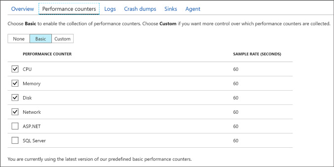


Configure alerts
After your VM is configured to collect metrics, you can configure alert rules that can send an email, invoke a Webhook, run an Azure Automation runbook, or run a Logic App when certain conditions relative to a metric are met. Additionally, you can configure alert rules on logs that can trigger an email, an SMS message, or a Webhook when a particular log event is encountered.
Configuring alerts
To configure alerts using the portal, complete the following steps:
Navigate to the blade for your VM in the Azure Portal.
In the Menu, scroll down to the Monitoring group and select Alert rules.
On the Alert Rules blade, select Add metric alert to specify an alert rule that triggers based upon a metric. Provide a name for the rule, select the metric source, specify the condition, and then select the desired action to take when the condition is met.
Select Add Activity Log Alert to specify an alert rule that triggers based upon an event appearing in the activity log. Provide a name for the rule, specify the criteria that described the desired event, provide an action group name and short name, and then select the desired action to take when the event is matched.
Click OK to create the new rule.
Monitor metrics
You can assess the status and health of your VM by viewing its metrics in the portal, by querying table storage for diagnostic logs, or by downloading IIS logs from Azure Storage.
Monitoring metrics
Using the portal you can drill into charts and change the metrics displayed in detail by completing the following steps:
Navigate to the blade for your VM in the Portal.
From the menu, scroll down to the Monitoring group and select Metrics.
Select from the desired metrics from the list of available host and guest OS metrics.
The charts will update to display the desired metrics (Figure 1-37).
Use the Chart type drop down to change the visualization used and the Time range drop down to adjust the time period over which the metric is displayed (Figure 1-38).


Viewing event logs, diagnostic infrastructure logs, and application logs
You can view Windows event logs, the diagnostic infrastructure logs, and application logs by querying their respective tables (WADWindowsEventLogsTable, WADDiagnosticInfrastructureLogsTable, WADLogsTable) in Table storage using the tool of your choice. The following steps demonstrate how to do this using Visual Studio.
Launch Visual Studio.
On the View menu, click Server Explorer.
Expand the node labeled Azure. If prompted to do so, log in with your organizational account or the Microsoft account that is associated with the website you want to manage.
Expand Storage.
Expand the storage account containing the logs.
Expand Tables.
Right-click the table you want to query and select View Table to display its contents.
Viewing IIS logs
IIS logs can be retrieved from Blob storage using the tool of your choice. The following steps show how to do this using Visual Studio.
Launch Visual Studio.
On the View menu, click Server Explorer.
Expand the node labeled Azure. If prompted to do so, log in with your organizational account or the Microsoft account that is associated with the website you want to manage.
Expand Storage.
Expand Blobs.
Right-click wad-iis-logs and select View Blob Container to display its contents. Each log is listed, so double-click a log to download and open it.
Viewing boot diagnostics
The collected boot diagnostic logs or screenshot can be viewed using the Azure Portal.
Navigate to the blade for your VM in the Azure Portal.
From the menu, scroll down to then Support + Troubleshooting section and select Boot diagnostics.
For Linux VM’s the log will be displayed by default. From the command bar, use the Log button to download the log file or the Screenshot button to download the latest screenshot bitmap. For Windows VM’s, the latest screenshot will be displayed. Use the Screenshot button in the command bar to download a copy of the screenshot.
Skill 1.6: Manage ARM VM Availability
For an application running in Azure to remain highly available, it should run across multiple identical Virtual Machines so that the overall availability of the application is not affected when a small subset of the Virtual Machines are unavailable due to events like updates, networking failures and power failures. The actual approach to achieving this requires the proper configuration of availability sets and may require the use of the Azure Load Balancer.
This skill covers how to:
![]() Configure availability sets
Configure availability sets
![]() Combine the Load Balancer with availability sets
Combine the Load Balancer with availability sets
Configure availability sets
Availability sets enable you to improve the availability of VMs deployed to your cloud service by identifying to Azure a group of VMs that should never be brought down simultaneously during updates and that should be physically separated (that is, connected to a separate power source and network switch) so that the failure of a host does not cause all of the VMs in that group to fail. In other words, an availability set does what it says, it describes a set of VMs that Azure will respect to ensure that the service provided by the VMs remains available because at no point in time should all VMs in the set be offline.
By defining an availability set, you constrain how Azure locates your VM in update and fault domains.
Update domains
An update domain constrains how Azure performs updates to the underlying host machine that is running your VM. VMs located in separate update domains will never experience an update (or a restart of the host machine) at the same time. Azure uses five update domains by default in which it places your VMs in a round-robin process. When you add VMs to an availability set, Azure places the first five VMs in separate update domains, then continues to distribute additional VMs across update domains in a round-robin fashion, assigning the sixth VM to the first update domain, the seventh VM to the second update domain, and so on until all VMs have been assigned to one of the five update domains. The constraint on update domains is that Azure will never bring down more than one update domain at a time, effectively ensuring that when Azure updates the host machines, never more than 50 percent of your VMs will be affected (assuming you have two VMs) or, if you are filling all update domains, 20 percent (assuming you have five or more VMs).
Fault domains
Whereas update domains apply to the roll out of host machine updates, fault domains consider isolation in terms of power and network. When two VMs are placed in separate fault domains, they will never be located such that they share the power source or network switch, which basically means that they will not be on the same host machine or even on the same server rack as one another. When you add VMs to an availability set, they are distributed between by default between two fault domains in round-robin fashion.
In short, the strategic placement of your VMs across update and fault domains is controlled simply by their membership in an availability set.
Availability sets and application tiers
For multi-tier applications (such as those having separate front-end, middle, and back-end tiers), it is a best practice to place all the VMs belonging to a single tier in a single availability set and to have separate availability sets for each application tier. This helps ensure that at no point are all instances for a particular tier in the solution down and, therefore, that the complete solution across all tiers is available.
Configuring availability sets
There are multiples ways to define an availability set and to configure the VMs that belong to it. When you are creating a new VM, you can create a new availability set and add the VM to it, or you can specify an existing availability set and add the new VM to it. The same options exist if you have an existing VM.
Configuring an availability set for a new ARM VM
To create a new VM and associate it with an availability group, complete the following steps:
Navigate to the portal accessed via https://manage.windowsazure.com.
Select New on the command bar.
Within the Marketplace list, select the Compute option.
On the Compute blade, select the image for the version of Windows Server or Linux you want for your VM.
On the Basics blade, provide a name for your VM.
Select the VM disk type: a VM disk type of SSD will use Premium Storage and a type of HDD will use Standard Storage.
Provide a user name and password (or SSH public key), and choose the subscription, resource group and location into which you want to deploy.
Select OK.
On the Choose a size blade, select the desired tier and size for your VM.
Choose select.
On the Settings blade, under the High availability header, select Availability set (Figure 1-39).
Choose an existing Availability Set (Figure 1-40), or select the Create new option to define a new availability set. When defining a new availability set, provide a name for the availability set, the desired number of fault domains (between 1 and 3), the number of update domains (between 1 and 20).
Select OK.
Select OK once more.
On the Purchase blade, review the summary and select Purchase to deploy the VM.


Configuring an availability set for an existing ARM VM
Once a VM has been deployed, you cannot alter the availability set to which it belongs. The availability set can only be configured when creating a virtual machine. You must recreate the virtual machine to move it in or out of an availability set.
Configuring an availability set using Windows PowerShell
An availability set can be created using Windows PowerShell only during the process of creating a new VM:
New-AzureRmAvailabilitySet -ResourceGroupName "<ResourceGroupName>"
-Name "<AvailabilitySetName>" -Location "<Location>"
$AvailabilitySet = Get-AzureRmAvailabilitySet -ResourceGroupName "<ResourceGroupName>"
-Name "<AvailabilitySetName>"
$VirtualMachine = New-AzureRmVMConfig -VMName "<VirtualMachineName>"
-VMSize "<VM_Size>" -AvailabilitySetID $AvailabilitySet.Id
After the preceding command, use the following cmdlet to provision and start the VM:
Start-AzureRmVM -ResourceGroupName "<ResourceGroupName>"
-Name "<VirtualMachineName>"
Combine the Load Balancer with availability sets
The Azure Load Balancer enables you to distribute traffic entering from either a public IP address or from an internal IP to the collection of VMs in an availability set in a round robin manner. It can also automatically remove non-responsive VMs from rotation so that they are not routed traffic when they are unavailable.
Configuring a Load Balancer for VMs in an Availability Set
Once you have deployed your VMs in an availability set, you can perform load balancing between them by performing the following steps:
In the Azure Portal, select New and search for Load Balancer and select the Load Balancer entry.
On the Load Balancer select Create.
On the Create a Load Balancer, provide a name for the new load balancer.
If you want to load balance traffic from the public Internet:
For the type, select Public.
Select Public IP address and select an existing Public IP or create a new one. If you create a new Public IP, provide a name for the Public IP and select if it should have a dynamically assigned IP or a statically assigned IP by setting the Assignment toggle to Dynamic or Static respectively (Figure 1-41).
If you want to load balance traffic only within your Virtual Network:
For the type, select Internal.
Select Virtual network and choose an existing Virtual Network.
Select Subnet and choose a subnet within the Virtual Network.
Select if the Load Balancer (Figure 1-42) should have a dynamically assigned IP or a statically assigned IP by setting the IP address assignment toggle to Dynamic or Static respectively.
Select the Subscription, Resource Group and Location as appropriate. Your VMs should exist in the same Location as you select for the Load Balancer.
Select create to deploy the Load Balancer.
When your Load Balancer is deployed, navigate to it in the Azure Portal.
From the menu, under the Settings header, select Backend Pools (Figure 1-43).
Select +Add.
On the Add backend pool blade, provide a name for the new Backend pool, and in the Associated to dropdown list, select Availability Set.
In the dropdown that appears, select the Availability Set that contains your VMs to load balance.
For each VM that you want to add to backend pool, perform the following:
Select +Add target network IP configuration.
Select the VM from the Target virtual machine dropdown.
Select the IP configuration for the VM from the Network IP configuration dropdown.
Select OK (Figure 1-44).
From the menu, under the Setting header, select Health probes.
Select +Add.
Provide a name for the health probe (Figure 1-45).
Choose protocol (either HTTP or TCP).
Provide the Port that the probe will use in testing the VMs availability.
If you chose the HTTP protocol, also specify the path on the HTTP endpoint to use when probing the VMs availability.
Specify an interval in seconds between probe attempts in the Interval field.
In the Unhealthy threshold, specify the number of consecutive probe failures that must occur before the VM is considered unhealthy.
Select OK.
From the menu, under the Setting header, select Load balancing rules.
Select +Add.
On the Add load balancing rule, provide a name.
Set the protocol to TCP or UDP as desired.
Specify the Port for incoming traffic.
Specify the Backend port used when communicating with the VMs.
From the Backend pool dropdown, select the pool your previously created.
From the Health probe dropdown, select the health probe you previously created (Figure 1-46).
Select OK to apply load balancing rule.


Skill 1.7: Design and implement DevTest Labs
Azure DevTest Labs is a service designed to help developers and testers quickly spin up virtual machines (VMs) or complete environments in Azure, enabling rapid deployment and testing of applications. This allows you to easily spin up and tear down development and test resources, minimizing waste and providing better control cost. You can test the latest version of your application by quickly provisioning environments using reusable templates and artifacts, integrate it with your deployment pipeline, or create pre-provisioned environments for training and demos.
This skill covers how to:
![]() Create and manage custom images and formulas
Create and manage custom images and formulas
![]() Configure a lab to include policies and procedures
Configure a lab to include policies and procedures
![]() Configure cost management
Configure cost management
![]() Secure access to labs
Secure access to labs
![]() Use environments in a lab
Use environments in a lab
Navigate to the Azure portal, accessed via https://portal.azure.com.
From the main menu on the left side, select More services (at the bottom of the list), and then select DevTest Labs (Figure 1-47) from the list of available services.
In the DevTest Labs blade, select +Add (Figure 1-48).
On the Create a DevTest Lab blade:
Enter a Lab Name for the new lab.
Select the Subscription to associate with the lab.
Select a Location in which to store the lab.
Select Auto-shutdown to specify if you want to enable, and define parameters for, the automatic shutting down of all of the lab’s VMs. The auto-shutdown feature is mainly a cost-saving feature whereby you can specify when you want the VMs to automatically be shut down. You can change auto-shutdown settings after creating the lab by following the steps outlined in the Auto-shutdown section below.
Enter NAME and VALUE information for Tags if you want to create custom tagging that is added to every resource you will create in the lab. Tags are useful to help you manage and organize lab resources by category.
Select Create (Figure 1-49).


The deployment of a DevTest lab creates a new resource group. Within that resource group, you will find the following resources:
![]() The DevTest Lab instance
The DevTest Lab instance
![]() A Key vault instance
A Key vault instance
![]() A Storage account
A Storage account
![]() A Virtual network
A Virtual network
Add a VM to a lab
Upon initially accessing your DevTest Lab, you will want to create your first VM. This can be accomplished using a custom image or formula, or by using a pre-loaded base Marketplace image. This section focuses on the latter, and defers coverage of using custom images and formulas to the Create and manage custom images and formulas section.
Navigate to the blade for your DevTest Lab in the Azure portal.
On the lab’s Overview blade, select +Add (Figure 1-50).
On the Choose a base blade, select a base image for the VM.
On the Virtual Machine blade:
Enter a name for the new VM in the Virtual Machine Name text box.
Enter a User Name that is granted administrator privileges on the VM.
Enter a password in the text field labeled Type a value. We will cover the Use a saved secret check box in the Secure access to your lab section below.
The Virtual machine disk type determines which storage disk type is allowed for the VMs in the lab. Select Hard Drive Disks (HDD) or Solid-State Drives (SSD).
Select Virtual machine size, and select one of the predefined items that specify the processor cores, RAM size, and the hard drive size of the VM to create.
Select Artifacts and, from the list of artifacts, select and configure the artifacts that you want to add to the base image.
Select Advanced settings to configure the VM’s Network options, expiration policy, and Claim options. Set Make this machine claimable to Yes if you want the machine to be claimable by lab users.
Select Create to add the new VM to the lab (Figure 1-51).


When a VM is created, ownership is assigned to either you (the creator), or it can be made claimable. Claimable VMs are unassigned, and can be claimed by lab user. To make a VM claimable you can select Yes under Make this machine claimable on the Advanced settings blade during the VM creation process. It is also possible to make a VM you own claimable, by selecting Unclaim from the VM’s overview blade (Figure 1-52).
Unclaiming a VM will result in it being moved from your My Virtual Machines section to the Claimable Virtual Machines section on the lab’s blade.
Create and manage custom images and formulas
Custom images and formulas facilitate the rapid deployment of pre-configured VMs. The key difference between custom images and formulas is that a custom image is simply an image based on a VHD, while a formula is an image based on a VHD in addition to preconfigured settings, such as VM size, virtual network, subnet, and artifacts. These preconfigured settings are set up with default values that can be overridden at the time of VM creation. Both custom images and formulas can be used as bases for creating new VMs.
Creating custom images
Custom images provide a static, immutable way to create VMs from a desired configuration. They allow you to pre-install all the software that you need in a Virtual Hard Disk (VHD) file, and then use that VHD file to create a VM. Because the software is already installed, the VM creation time is much quicker. In addition, custom images can be used to clone VMs by creating a custom image from a VM, and then creating VMs based on that custom image.
Pros of using custom images:
![]() VM provisioning is fast as nothing changes after the VM is spun up from the image.
VM provisioning is fast as nothing changes after the VM is spun up from the image.
![]() VMs created from a single custom image are identical.
VMs created from a single custom image are identical.
Cons of using custom images:
![]() If you need to update any aspect of the custom image, the image must be recreated.
If you need to update any aspect of the custom image, the image must be recreated.
There are several ways to create a custom image in Azure DevTest Labs. You can create an image from an existing VM, or create on from a VHD, using either the Azure portal or PowerShell. Before creating a custom image from a VHD, the VHD needs to be uploaded to the storage account associated with the lab in which you are creating the custom image.
Create a custom image from a provisioned virtual machine
To create a custom image from a provisioned VM, following these steps:
Navigate to the blade of your DevTest Labs instance.
On your lab’s blade, select All virtual machines (Figure 1-53).
On the All virtual machines blade, select the VM from which you want to create the custom image.
On the VM’s blade, select Create custom image (Figure 1-54).
On the Custom image blade (Figure 1-55), enter a name and description for your custom image. This information is displayed in the list of bases when you create a VM.
Select whether sysprep was run on the VM. If the sysprep was not run on the VM, specify whether you want sysprep run when a VM is created from this custom image.
Select OK when finished to create the custom image.


Create a custom image from a VHD using the Azure Portal
To create a custom image from a VHD using the Azure portal, complete the following steps:
Navigate to the blade of your DevTest Labs instance.
From your lab’s Configuration and policies blade, select Custom images (Figure 1-56).
On the Custom images blade, select +Add (Figure 1-57).
Enter the name of the custom image. This will be displayed in the list of base images when creating a VM.
Enter a description for the custom image. This will be displayed in the list base images.
Select an OS Type – Windows or Linux.
If Windows is selected as the OS Type, select whether sysprep has been run on the VHD image.
Select a VHD image.
Select OK to create the custom image (Figure 1-58).


Create a custom image from a VHD using PowerShell
To create a custom image from a VHD using PowerShell, complete these steps:
At a PowerShell prompt, log into your Azure account with the following call to the Login-AzureRmAccount cmdlet.
Login-AzureRmAccount
Select the desired Azure subscription by calling the Select-AzureRmSubscription cmdlet. Replace the placeholder for $subscriptionId variable with a valid Azure subscription ID.
$subscriptionId = '<Specify your subscription ID here>'
Select-AzureRmSubscription -SubscriptionId $subscriptionIdGet the lab object by calling the Get-AzureRmResource cmdlet. Replace the following placeholders for the $labRg and $labName variables with the appropriate values for your environment.
$labRg = '<Specify your lab resource group name here>'
$labName = '<Specify your lab name here>'
$lab = Get-AzureRmResource -ResourceId ('/subscriptions/' + $subscriptionId +
'/resourceGroups/' + $labRg + '/providers/Microsoft.DevTestLab/labs/' + $labName)Get the lab storage account and lab storage account key values from the lab object.
$labStorageAccount = Get-AzureRmResource -ResourceId
$lab.Properties.defaultStorageAccount
$labStorageAccountKey = (Get-AzureRmStorageAccountKey -ResourceGroupName
$labStorageAccount.ResourceGroupName -Name
$labStorageAccount.ResourceName)[0].ValueReplace the following placeholder for the $vhdUri variable with the URI to your uploaded VHD file. You can get the VHD file’s URI from the storage account’s blob blade in the Azure portal.
$vhdUri = '<Specify the VHD URI here>'
Create the custom image using the New-AzureRmResourceGroupDeployment cmdlet. Replace the following placeholders for the $customImageName and $customImageDescription variables to meaningful names for your environment.
$customImageName = '<Specify the custom image name>'
$customImageDescription = '<Specify the custom image description>'
$parameters = @{existingLabName="$($lab.Name)"; existingVhdUri=$vhdUri;
imageOsType='windows'; isVhdSysPrepped=$false; imageName=$customImageName;
imageDescription=$customImageDescription}
New-AzureRmResourceGroupDeployment -ResourceGroupName $lab.ResourceGroupName
-Name CreateCustomImage -TemplateUri 'https://raw.githubusercontent.com/
Azure/azure-devtestlab/master/Samples/201-dtl-create-customimage-from
-vhd/azuredeploy.json' -TemplateParameterObject $parameters
Delete a custom image
You may find that there are times when an image is no longer needed, and should be removed from your lab. To delete a custom image, complete the following steps:
Navigate to the blade of your DevTest Labs instance.
On the lab’s Overview blade, select Custom images.
On the Custom images blade, select the ellipsis to the right of the custom image you wish to delete, then select Delete on the context menu (Figure 1-59).
Select Yes to the deletion confirmation dialog.

Creating formulas
Formulas are lists of default property values, providing a dynamic way to create VMs from a desired configuration. When creating a VM from a formula, the default values can be used as-is, or modified. Like custom and Marketplace images, formulas provide a mechanism for fast VM provisioning. Like custom images, they enable you to create a base image from a VHD file. The base image can then be used to provision a new VM.
Pros of using formulas
![]() Changes in the environment can be captured on the fly via artifacts. For example, if you want a VM installed with the latest bits from your release pipeline, you can specify an artifact that deploys the latest bits or enlists the latest code in the formula together with a target base image. Whenever this formula is used to create VMs, the latest bits/code are deployed/enlisted to the VM.
Changes in the environment can be captured on the fly via artifacts. For example, if you want a VM installed with the latest bits from your release pipeline, you can specify an artifact that deploys the latest bits or enlists the latest code in the formula together with a target base image. Whenever this formula is used to create VMs, the latest bits/code are deployed/enlisted to the VM.
![]() Formulas can define default settings that custom images cannot provide.
Formulas can define default settings that custom images cannot provide.
![]() The settings saved in a formula are default values, and can be modified when the VM is created.
The settings saved in a formula are default values, and can be modified when the VM is created.
Cons of using formulas
![]() Creating a VM from a formula can take more time than creating a VM from a custom image.
Creating a VM from a formula can take more time than creating a VM from a custom image.
Anyone in the DevTest Labs User role can create VMs using a formula as a base. There are two ways to create formulas:
![]() From a base (custom image, Marketplace image, or another formula)—Use when you want to define all the characteristics of the formula.
From a base (custom image, Marketplace image, or another formula)—Use when you want to define all the characteristics of the formula.
![]() From an existing lab VM—Use when you want to create a formula based on the settings of an existing VM.
From an existing lab VM—Use when you want to create a formula based on the settings of an existing VM.
Create a formula from a base
The following steps outline the process of creating a formula for a custom image, Marketplace image, or another formula.
Navigate to the blade of your DevTest Labs instance.
From your lab’s blade, select Configuration and policies (Figure 1-60).
On the Configuration and policies blade, select Formulas (reusable bases).
Select +Add on the Configuration and policies – Formulas (reusable bases) blade (Figure 1-61).
On the Choose a base blade, select an image to use for the formula.
On the Create formula blade:
Enter a name for the formula into the Formula name text box. This value is displayed in the list of base images when you create a VM.
Enter a description for the formula. This value is available from the formula’s context menu when you create a VM.
Enter a User name, which will have administrative privileges on the VM.
Enter a password.
Specify either HDD (hard-disk drive) or SSD (solid-state drive) to indicate which storage disk type is allowed for the virtual machines provisioned using this base image.
Select one of the predefined items that specify the processor cores, RAM size, and the hard drive size of the VM to create.
Select to open the Add artifacts blade, in which you select and configure the artifacts that you want to add to the base image.
Select to open the Advanced blade where you configure the following settings:
Virtual network - Specify the desired virtual network. Subnet - Specify the desired subnet. IP address configuration - Specify if you want the Public, Private, or Shared IP addresses. For more information about shared IP addresses, see Understand shared IP addresses in Azure DevTest Labs. Make this machine claimable - Making a machine “claimable” means that it will not be assigned ownership at the time of creation. Instead lab users will be able to take ownership (“claim”) the machine in the lab’s blade.Select Create to create the formula (Figure 1-62).


Create a formula from a VM
To create a formula based on an existing VM, complete the following steps:
Navigate to the blade of your DevTest Labs instance.
From your lab’s Overview blade, select the VM from which you wish to create the formula (Figure 1-63).
On the VM’s blade (Figure 1-64), select Create formula (reusable base).
On the Create formula blade, enter a Name and Description for your new formula (Figure 1-65).
Select OK to create the formula.


Modify a formula
After creating a formula, it is possible to modify the properties of that formula. To modify an existing formula, follow these steps:
Navigate to the blade of your DevTest Labs instance.
On your lab’s Overview blade (Figure 1-66), select Formulas (reusable bases).
On the Lab formulas blade, select the formula you wish to modify (Figure 1-67).
On the Update formula blade, make the desired edits, and select Update (Figure 1-68).


Delete a formula
To delete a formula, complete the steps below:
Navigate to the blade of your DevTest Labs instance.
On your lab’s Overview blade, select Formulas (reusable bases).
On the Lab formulas blade, select the ellipsis to the right of the formula you wish to delete, then select Delete on the context menu (Figure 1-69).
Select Yes to the deletion confirmation dialog.

Configure a lab to include policies and procedures
In Azure DevTest Labs, a lab is defined as the infrastructure that encompasses a group of resources, such as VMs. Labs enable you to better manage those resources by specifying limits and quotas. For each lab you create, you can control cost and minimize waste by managing policies (settings).
Configure allowed virtual machine sizes policy
The policy for setting the allowed VM sizes helps to minimize lab waste by enabling you to specify which VM sizes are allowed in the lab. If this policy is activated, only VM sizes from this list can be used to create VMs, allowing you to be very specific about what size VMs can be deployed into your lab environment. To configure the virtual machine sizes allowed in your lab, complete the following steps:
Navigate to the blade of your DevTest Labs instance.
On your lab’s Overview blade, select Configuration and policies, under Settings (Figure 1-70).
Select Allowed virtual machine sizes under Settings, on the Configuration and policies blade (Figure 1-71).
Select On to enable this policy, and Off to disable it (Figure 1-72).
If enabled, select one or more VM sizes that you want to be allowed the creation of in your lab.
Select Save.


Configure virtual machines per user policy
The Virtual machines per user policy allows you to specify the maximum number of VMs that can be created or claimed by an individual user. You can also specify limits on the number of VMs using premium OS disks. Should a user attempt to create or claim a VM when their user limit has been met, an error message indicating that the VM cannot be created/claimed will be displayed. To manage the virtual machines per user policy, follow the steps below:
Navigate to the blade of your DevTest Labs instance.
On your lab’s blade, select Configuration and policies.
On the Configuration and policies blade, select Virtual machines per user (Figure 1-73).
Select Yes to enable limiting the number of virtual machines per user, and No to disable limits.
If yes is selected, enter a numeric value indicating the maximum number of VMs that can be created or claimed by a user (Figure 1-74).
Select Yes to enable limiting the number of VMs using premium OS disks (SSD), and No to remove limits on premium disk utilization.
If Yes is selected, enter a numeric value to specify the limit of VMs that can be created using SSDs.
Select Save to save your policy settings.


Configure virtual machines per lab policy
The policy for Virtual machines per lab allows you to specify the maximum number of VMs that can be created for the current lab, setting a limitation on the overall lab itself. Like the Virtual machines per user policy, you can also set limitations on the use of premium OS disks. If any user attempts to create a VM when the lab limit has been met, an error message indicates that the VM cannot be created. The virtual machines per lab policy can be configured by completing the following steps:
Navigate to the blade of your DevTest Labs instance.
On the lab’s blade, select Configuration and policies.
On the Configuration and policies menu, select Virtual machines per user (Figure 1-75).
Select Yes to enable limiting the number of virtual machines per user, and No to disable limits.
If Yes is selected, enter a numeric value indicating the maximum number of VMs that can be created in the lab (Figure 1-76).
Select Yes to enable limiting the number of virtual machines using premium OD disks (SSD), and No to disable limits on premium disk utilization.
If Yes is selected, enter a numeric value to specify the limit.
Select Save to save your policy settings.


Configure auto-shutdown policy
The auto-shutdown policy in Azure DevTest Labs is one of the most important policies for helping you to minimize lab waste and control cost, allowing you to specify a time that the lab’s VMs will automatically shut down. This helps to prevent incurring costs when the VMs are not in use, and ensures VMs are shut down, even when you forget to do it at the end of a work day. To configure the auto-shutdown policy, follow the below steps:
Navigate to the blade of your DevTest Labs instance.
On the lab’s Configuration and policies blade, select Auto-shutdown (Figure 1-77).
Select On to enable this policy, and Off to disable it (Figure 1-78).
If you enable this policy, specify the time and time zone to shut down all VMs in the current lab.
Specify Yes or No for the option to send a notification before auto-shutdown. Notifications will be sent 15 minutes prior to the specified auto-shutdown time. If you specified Yes, enter either a Webhook URL endpoint or an email address to receive the notifications.
Select Save.


By default, once enabled, the auto-shutdown policy applies to all VMs in the current lab. This policy can be overridden on each individual VM in the lab, enabling more fine-tuned management of the policy. To alter this setting for a specific VM, complete the steps below:
Open the target VM’s blade.
Select the Auto-shutdown tile on the VM’s blade (Figure 1-79).
On the Auto-shutdown blade, select On to enable the policy, or Off to disable it. If On is selected, enter a scheduled shutdown time, and time zone, and specify if notifications should be sent before auto-shutdown. If notifications are to be sent, provide a Webhook URL or email address to send notifications (Figure 1-80).


Configure auto-start policy
Azure DevTest Labs’ auto-start policy lets you specify when the VMs in the current lab should be automatically started, allowing all VMs to be started at a specific day and time. For example, if you want all your VMs to start at 7:00 AM each weekday, you can set up the policy to accommodate that configuration. Complete the following steps to configure the auto-start policy:
Navigate to the blade of your DevTest Labs instance.
On your lab’s Configuration and policies blade, select Auto-start (Figure 1-81).
Select On to enable this policy, and Off to disable it (Figure 1-82).
If you enable this policy, specify the scheduled start time, time zone, and the days of the week for which the time applies.
Select Save.


Like the auto-shutdown policy, the auto-start policy applies to all VMs in the current lab, once enabled. The steps to modify this policy for an individual VM are similar to those for the auto-shutdown policy, but you will select the Auto-start tile on the VM’s blade, and modify the policy from there.
Set expiration date policy
Another option for managing the life of a VM is the ability to set an expiration date for the VM. This option is available when creating a new VM, and could be used if you want to ensure the VM is automatically deleted at a specified date and time. To set the expiration date for a VM:
During the VM creation process, select Advanced settings on the Virtual machine blade.
Choose the calendar icon to specify a date and time on which the VM will be automatically deleted. By default, VMs never expire.
Select OK on the Advanced settings blade (Figure 1-83).

Configure cost management
Azure DevTest Labs was designed to help development teams more effectively manage costs and resources. One of the key features of this is Cost Management, which allows you to track the cost associated with operating your lab. You can also view trends, set cost targets and thresholds, and configure alerts to keep you informed about your monthly costs. Cost threshold targets allow you to monitor usage throughout the month, and potentially alter behavior accordingly if you see spending happening faster than anticipated during a specified time period.
To view your Cost trend chart, navigate to the blade for your DevTest Labs instance, and select Cost trend from the Configuration and policies blade of your lab (Figure 1-84).

Cost trend
The Monthly Estimated Cost Trend chart displays the current calendar month’s estimated cost-to-date, and the projected end-of-month cost for the current calendar month (Figure 1-85).

Azure DevTest Labs allows you to modify the time span displayed on the chart, specify target costs, and set up notifications. You can configure these options by completing the following steps:
From the Cost trend blade, select Manage target (Figure 1-86).
On the Manage target blade:
Select the time period you would like displayed on the chart. Monthly is the default, and will display the current month. Selecting Fixed allows you to specify a set time period to display on the chart (Figure 1-87).
Specify a numeric value (in USD) for your target monthly cost (Figure 1-88).
Select any desired cost thresholds, and on the Cost threshold blade, specify whether to send notifications, and if you would like the threshold displayed on the trend chart, then select OK (Figure 1-89).
If you chose to enable notifications, click to add an integration of a Webhook under Cost integrations. The lab will post a notification to the specified endpoint if lab spending reaches a threshold for which you have opted to receive notification (Figure 1-90).
On the Configure notification blade, enter a Webhook URL, and Select OK (Figure 1-91).
Select OK to save the trend chart targets.


The estimated cost value is the current calendar month’s estimated cost-to-date. The projected cost is the estimated cost for the entire calendar month, calculated using the lab cost for the previous five days. These cost numbers are rounded up the nearest whole number, and do not reflect actual costs.
Cost by resource
To provide you with more insight into cost of operating each individual resource in your lab, you can also view a breakdown of cost by resource. To view this breakdown, follow these steps:
Navigate to the blade of your DevTest Labs instance.
On the Configuration and policies blade for your lab, select Cost by resource (Figure 1-92).
View the list of individual resources, and how much money (in USD) is being spent per resource (Figure 1-93).
The list can be sorted to easier view those resources which have the most associated cost.


Secure access to labs
Security access in DevTest Labs is determined by Azure Role-Based Access Control (RBAC). To understand how access works, it helps to understand the differences between a permission, a role, and a scope as defined by RBAC.
![]() Permission Defined access to a specific action (e.g. read-access to all virtual machines).
Permission Defined access to a specific action (e.g. read-access to all virtual machines).
![]() Role A set of permissions that can be grouped and assigned to a user. For example, the subscription owner role has access to all resources within a subscription.
Role A set of permissions that can be grouped and assigned to a user. For example, the subscription owner role has access to all resources within a subscription.
![]() Scope A level within the hierarchy of an Azure resource, such as a resource group, a single lab, or the entire subscription.
Scope A level within the hierarchy of an Azure resource, such as a resource group, a single lab, or the entire subscription.
Using RBAC, you can segregate duties within your team into roles where you grant only the amount of access necessary to users to perform their jobs. The three RBAC roles most relevant to Azure DevTest Labs are Owner, DevTest Labs User, and Contributor.
The Table 1-3 provides a breakdown of the actions that can be performed by users in each of these roles.
TABLE 1-3 Actions that can be performed by users in specified roles.
Actions users in this role can perform |
DevTest Labs User |
Owner |
Contributor |
LAB TASKS |
|
|
|
Add users to a lab |
No |
Yes |
No |
Update cost settings |
No |
Yes |
Yes |
VM BASE TASKS |
|
|
|
Add and remove custom images |
No |
Yes |
Yes |
Add, update, and delete formulas |
Yes |
Yes |
Yes |
Whitelist Azure Marketplace images |
No |
Yes |
Yes |
VM TASKS |
|
|
|
Create VMs |
Yes |
Yes |
Yes |
Start, stop, and delete VMs |
Only VMs created by the user |
Yes |
Yes |
Update VM policies |
No |
Yes |
Yes |
Add/remove data disks to/from VMs |
Only VMs created by the user |
Yes |
Yes |
ARTIFACT TASKS |
|
|
|
Add and remove artifact repositories |
No |
Yes |
Yes |
Apply artifacts |
Yes |
Yes |
Yes |
Add an owner or user at the lab level
Owners and users can be added at the lab level via the Azure portal. This includes external users with a valid Microsoft account (MSA). The following steps guide you through the process of adding an owner or user to a lab in Azure DevTest Labs:
Navigate to the blade of your DevTest Labs instance.
On your lab’s blade, select Configuration and policies.
On the Configuration and policies blade (Figure 1-94), select Access control (IAM).
Select +Add
On the Add permission blade, select a role, Owner or DevTest Labs User (Figure 1-95).
On the Add permissions blade, enter a name or an email address, and select the user (Figure 1-96).
Click Save.


Add an external user to a lab using PowerShell
In addition to adding users in the Azure portal, you can add an external user to your lab using a PowerShell script.
The PowerShell script below assumes that the specified user has been added as a guest to the Active Directory, and will fail if that is not the case. To add a user not in the Active Directory to a lab, use the Azure portal to assign the user to a role as illustrated in the section, Add an owner or user at the lab level, above.
To add an external user to a lab, complete the following steps:
At a PowerShell prompt, log into your Azure account with the following call to the Login-AzureRmAccount cmdlet.
Login-AzureRmAccount
Select the desired Azure subscription by calling the Select-AzureRmSubscription cmdlet. Replace the placeholder for $subscriptionId variable with a valid Azure subscription ID.
$subscriptionId = '<Specify your subscription ID here>'
Select-AzureRmSubscription -SubscriptionId $subscriptionIdRetrieve the user object with the Get-AzureRmAdUser cmdlet. Replace the $userDisplayName placeholder with the appropriate value.
$userDisplayName = "<Specify the User's Display Name here>"
$adObject = Get-AzureRmADUser -SearchString $userDisplayNameGet the lab object by calling the Get-AzureRmResource cmdlet. Replace the following placeholders for the $labRg and $labName variables with the appropriate values for your environment.
$labRg = '<Specify your lab resource group name here>'
$labName = '<Specify your lab name here>'
$lab = Get-AzureRmResource -ResourceId ('/subscriptions/' + $subscriptionId +
'/resourceGroups/' + $labRg + '/providers/Microsoft.DevTestLab/labs/' + $labName)Create the role assignment, using the New-AzureRmRoleAssignment cmdlet.
New-AzureRmRoleAssignment -ObjectId $adObject.Id -RoleDefinitionName 'DevTest
Labs User' -Scope $labId
Use lab settings to set access rights to the environment
Lab settings allow you to modify the access rights of your lab users to the resource group containing your lab resources. By giving your lab users Contributor access rights, you enable them to edit resources, such as SQL Server or Cosmos DB, in the resource group that contains your lab environment. By default, lab users have Reader access rights, and cannot change the resources in the resource group.
Navigate to the blade of your DevTest Labs instance.
On the DevTest Lab’s Overview blade, select Configuration and policies.
On the lab’s Configuration and policies menu, select Lab settings (Figure 1-97).
Specify whether lab users should have Contributor or Reader access rights on the environment resource group (Figure 1-98).
Select Save.


Use environments in a lab
The Azure portal enables you to easily create and add VMs to your lab one at a time. Sometimes, however, there is a requirement to deploy an environment containing multiple VMs, such as a multi-tier web app or a SharePoint farm. For this scenario, you can use Azure Resource Manager (ARM) templates to spin up a complete environment in DevTest labs, allowing your infrastructure to be as complicated as it needs to be for your environment.
Following infrastructure-as-code and configuration-as-code best practices, environment templates are managed in source control. Azure DevTest Labs loads all ARM templates directly from your GitHub or VSTS Git repositories. As a result, Resource Manager templates can be used across the entire release cycle, from the test environment to the production environment.
Configure an ARM template repository
To provide the greatest flexibility, Azure DevTest Labs allow you to build your own repositories, which can contain multiple environment templates, each in a separate folder. There are a couple of rules to follow for organizing your Azure Resource Manager templates in a repository:
The master template file must be named azuredeploy.json.
If you want to use parameter values defined in a parameter file, the parameter file must be named azuredeploy.parameters.json.
You can use the parameters _artifactsLocation and _artifactsLocationSasToken to construct the parametersLink URI value, allowing DevTest Labs to automatically manage nested templates.
Metadata can be defined to specify the template display name and description. This metadata must be in a file named metadata.json. The following example metadata file illustrated how to specify the display name and description:
{
"itemDisplayName": "<your template name>",
"description": "<description of the template>"
}
With your ARM template added to the repo, you are now ready to add the repository to your lab. To add a repository to your lab using the Azure portal, follow the steps below:
Navigate to the blade of your DevTest Labs instance.
On your lab’s blade, select Configuration and policies.
From the Configuration and policies blade, select Repositories. The Repositories blade (Figure 1-99) lists the repositories that have been added to the lab. A repository named Public Repo is automatically generated for all labs, and connects to the DevTest Labs GitHub repo that contains several VM artifacts for your use.
Select +Add to add your Azure Resource Manager template repository.
When the second Repositories blade opens, enter the necessary information as follows:
Enter a name for the repository.
Enter the GIT HTTPS clone URL from GitHub or Visual Studio Team Services account.
Enter the branch name to access your Azure Resource Manager template definitions.
The personal access token is used to securely access your repository. To get your token from Visual Studio Team Services, select <YourName> > My profile > Security > Public access token. To get your token from GitHub, select your avatar followed by selecting Settings > Public access token.
Using one of the two input fields, enter a folder path that starts with a forward slash - / - and is relative to your Git clone URI to either your artifact definitions (first input field) or your Azure Resource Manager template definitions (Figure 1-100).
Select Save (Figure 1-101).


Create an environment from an ARM template
Once an ARM template repository has been configured in the lab, your lab users can create an environment using the Azure portal by following the steps below:
Navigate to the blade of your DevTest Labs instance.
On your lab’s Overview blade, select +Add.
On the Choose a base blade, you will see resources with a Type of ARM template listed first. Select the desired ARM Template.
On the Add blade, enter an Environment name value. This is what will be displayed to your users in the lab. The remaining input fields come from the parameters defined in the ARM template. If default values are defined in the template or the azuredeploy.parameters.json file is present, default values are displayed in those input fields. For parameter types of secure string, you can use the secrets store in the lab’s personal secret store (Figure 1-102).
Select Add to create the environment. The environment starts provisioning immediately with the status displaying in the My Virtual Machines list. A new resource group is automatically created by the lab to provision all the resources defined in the ARM template (Figure 1-103).
Once the deployment of the environment completes, select the environment in the My Virtual Machines list to open the resource group blade, and browse all the resources provisioned in the environment (Figure 1-104).
You can also expand the environment in the My Virtual Machines list to view just the list of VMs that are provisioned in the environment (Figure 1-105).
You can select any of the resources in the environment to view the available actions, such as applying artifacts, attaching data disks, changing the auto-shutdown time, and more (Figure 1-106).


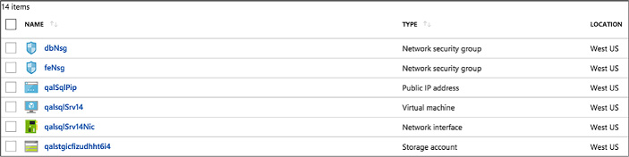


Thought experiment
In this thought experiment, apply what you’ve learned about this skill. You can find answers to these questions in the “Answers” section at the end of this chapter.
Your solution architecture has two tiers: a front-end web tier that you want to configure the so that is available and scales out during the busiest times, which are weekdays, and a diagnostics VM that enables you to analyze any issues with the web tier VM instances.
How would you place the VMs within Scale Sets and what constraints would you need to ensure you meet them?
How would you configure scaling?
You should ensure that you create a Virtual machine scale set for the web tier VM’s The diagnostic VM, since it does not have any scaling needs, should not be placed in a Virtual machine scale set, but it should be deployed in the same Virtual Network as used by the Scale Set so that it can reach the VM instances across the network.
You should configure Autoscale on the Scale Set with a condition that increases the VMs count to the desired capacity on weekdays and a default condition that sets the VM count that is in effect at all other times
Chapter summary
![]() There are two approaches to identifying supported workloads in Azure: looking for explicit support by a listing in the Marketplace and performing a manual comparison of the workload requirements against the capacities of VMs.
There are two approaches to identifying supported workloads in Azure: looking for explicit support by a listing in the Marketplace and performing a manual comparison of the workload requirements against the capacities of VMs.
![]() New VMs can be created by uploading a VM you have already created on-premises or by instantiating one from a selection of pre-built images that are available in the Marketplace.
New VMs can be created by uploading a VM you have already created on-premises or by instantiating one from a selection of pre-built images that are available in the Marketplace.
![]() Azure supports the creation of “bare-bones” VMs that provide just Windows or Linux operating system from pre-built images available in the Marketplace.
Azure supports the creation of “bare-bones” VMs that provide just Windows or Linux operating system from pre-built images available in the Marketplace.
![]() The Marketplace provides the ability to provision single VMs with pre-configured applications. The example shown in this chapter provisions SQL Server in a VM.
The Marketplace provides the ability to provision single VMs with pre-configured applications. The example shown in this chapter provisions SQL Server in a VM.
![]() The Marketplace use ARM templates to deploy and configure a complex topology consisting of multiple VMs, such as a SQL Server AlwaysOn or a SharePoint farm, the network resources and any supporting resources required.
The Marketplace use ARM templates to deploy and configure a complex topology consisting of multiple VMs, such as a SQL Server AlwaysOn or a SharePoint farm, the network resources and any supporting resources required.
![]() The VM Agent is a very lightweight process. When installed on a VM, it makes it possible to bootstrap additional VM extensions such as DSC.
The VM Agent is a very lightweight process. When installed on a VM, it makes it possible to bootstrap additional VM extensions such as DSC.
![]() The Custom Script Extension makes it possible to download files from Azure Storage, run Windows PowerShell of Linux Shell scripts, and automate copying files and configuring a VM.
The Custom Script Extension makes it possible to download files from Azure Storage, run Windows PowerShell of Linux Shell scripts, and automate copying files and configuring a VM.
![]() DSC helps you avoid configuration drift by specifying the desired state for VM provisioning and subsequent updates.
DSC helps you avoid configuration drift by specifying the desired state for VM provisioning and subsequent updates.
![]() Azure VM sizes control the capacity of the resources available to a VM instance. The size can be scaled up and scaled down using the portal or Windows PowerShell.
Azure VM sizes control the capacity of the resources available to a VM instance. The size can be scaled up and scaled down using the portal or Windows PowerShell.
![]() Virtual machine scale sets enable you to easily manage the scale up and scale down of the number of instances of a particular virtual machine image.
Virtual machine scale sets enable you to easily manage the scale up and scale down of the number of instances of a particular virtual machine image.
![]() Autoscale can be used with Virtual Machine Scale Sets to adjust the capacity based on resource metrics or according to a schedule.
Autoscale can be used with Virtual Machine Scale Sets to adjust the capacity based on resource metrics or according to a schedule.
![]() Storage capacity for VMs is dictated by the scalability limits (IOPS, throughput, and maximum file size) of Azure Storage as well as per-VM limits that adjust with the VM size (the number of VHD disks that can be attached).
Storage capacity for VMs is dictated by the scalability limits (IOPS, throughput, and maximum file size) of Azure Storage as well as per-VM limits that adjust with the VM size (the number of VHD disks that can be attached).
![]() Azure VMs support Standard Storage and Premium storage in both unmanaged and managed variants.
Azure VMs support Standard Storage and Premium storage in both unmanaged and managed variants.
![]() Disk caching provides a cache on the machine hosting your VM that can avert the need to read from or write to Blob storage. The options are None, Read Only, and Read/Write.
Disk caching provides a cache on the machine hosting your VM that can avert the need to read from or write to Blob storage. The options are None, Read Only, and Read/Write.
![]() Geo-replication should not be used for Azure Storage accounts that store VHDs because the added redundancy does not provide additional protection against corrupting the data and may in fact result in data loss if you attempt to restore from a geo-replication.
Geo-replication should not be used for Azure Storage accounts that store VHDs because the added redundancy does not provide additional protection against corrupting the data and may in fact result in data loss if you attempt to restore from a geo-replication.
![]() Azure File storage enables you to use network shares to provide distributed access to files from your VMs.
Azure File storage enables you to use network shares to provide distributed access to files from your VMs.
![]() A VM can be configured to collect diagnostics data (that is, logs) as well as performance counter metrics (CPU percentage, memory utilization, and so on).
A VM can be configured to collect diagnostics data (that is, logs) as well as performance counter metrics (CPU percentage, memory utilization, and so on).
![]() Endpoint monitoring can be configured on a VM to provide outside-in monitoring of HTTP or HTTPS endpoints provided by your VM.
Endpoint monitoring can be configured on a VM to provide outside-in monitoring of HTTP or HTTPS endpoints provided by your VM.
![]() You can monitor various metrics using the management portal, and you can configure alerts on these metrics to send out emails when a metric threshold is exceeded.
You can monitor various metrics using the management portal, and you can configure alerts on these metrics to send out emails when a metric threshold is exceeded.
![]() Diagnostic logs can be retrieved from Azure Storage (Table or Blob storage, depending on the specific type of log).
Diagnostic logs can be retrieved from Azure Storage (Table or Blob storage, depending on the specific type of log).
![]() An availability set defines both the update domains and fault domains to which VMs are assigned.
An availability set defines both the update domains and fault domains to which VMs are assigned.
![]() VMs in the same update domain will not all be updated at the same time.
VMs in the same update domain will not all be updated at the same time.
![]() VMs in the same fault domain share either the same power supply, network switch or both.
VMs in the same fault domain share either the same power supply, network switch or both.
![]() An Azure Load Balancer can be used to load balance traffic between VMs in an availability set.
An Azure Load Balancer can be used to load balance traffic between VMs in an availability set.
![]() It is a best practice to deploy VMs that represent the same application tier in the same availability set.
It is a best practice to deploy VMs that represent the same application tier in the same availability set.
![]() Azure DevTest Labs allows you to quickly spin up virtual machines (VMs) or complete environments in Azure.
Azure DevTest Labs allows you to quickly spin up virtual machines (VMs) or complete environments in Azure.
![]() Custom images and formulas facilitate the rapid deployment of pre-configured VMs in DevTest Labs.
Custom images and formulas facilitate the rapid deployment of pre-configured VMs in DevTest Labs.
![]() Custom images provide a static, immutable way to create VMs from a desired configuration, and can be created from a provisioned VM, or from a VDH, using either PowerShell or the Azure portal.
Custom images provide a static, immutable way to create VMs from a desired configuration, and can be created from a provisioned VM, or from a VDH, using either PowerShell or the Azure portal.
![]() Formulas are modifiable lists of default property values, providing a dynamic way to create VMs from a desired configuration, and can be created from a base image or an existing VM.
Formulas are modifiable lists of default property values, providing a dynamic way to create VMs from a desired configuration, and can be created from a base image or an existing VM.
![]() DevTest Labs enable you to better manage resources by specifying limits and quotas, allowing you to better control cost and minimize waste by managing policies.
DevTest Labs enable you to better manage resources by specifying limits and quotas, allowing you to better control cost and minimize waste by managing policies.
![]() Security access in DevTest Labs is determined by Azure Role-Based Access Control (RBAC), mainly using the owner, DevTest Labs user, and contributor roles.
Security access in DevTest Labs is determined by Azure Role-Based Access Control (RBAC), mainly using the owner, DevTest Labs user, and contributor roles.
![]() Azure Resource Manager (ARM) templates can be used to spin up complete environments in DevTest labs, allowing your infrastructure to be as complicated as it needs to be for your environment.
Azure Resource Manager (ARM) templates can be used to spin up complete environments in DevTest labs, allowing your infrastructure to be as complicated as it needs to be for your environment.