
Chapter 3. Manage identity, application and network services
Beyond compute and storage features, Microsoft Azure also provides a number of infrastructure services for security and communication mechanisms to support many messaging patterns. In this chapter you learn about these core services.
Skills in this chapter:
![]() Skill 3.1: Integrate an app with Azure Active Directory (Azure AD)
Skill 3.1: Integrate an app with Azure Active Directory (Azure AD)
![]() Skill 3.2: Develop apps that use Azure AD B2C and Azure AD B2B
Skill 3.2: Develop apps that use Azure AD B2C and Azure AD B2B
![]() Skill 3.3: Manage Secrets using Azure Key Vault
Skill 3.3: Manage Secrets using Azure Key Vault
![]() Skill 3.4: Design and implement a messaging strategy
Skill 3.4: Design and implement a messaging strategy
Skill 3.1: Integrate an app with Azure AD
Azure Active Directory (Azure AD) provides a cloud-based identity management service for application authentication, Single Sign-On (SSO), and user management. Azure AD can be used for the following core scenarios:
![]() A standalone cloud directory service
A standalone cloud directory service
![]() Corporate access to Software-as-a-Service (SaaS) applications with directory synchronization
Corporate access to Software-as-a-Service (SaaS) applications with directory synchronization
![]() SSO between corporate and SaaS applications
SSO between corporate and SaaS applications
![]() Application integration for SaaS applications using different identity protocols
Application integration for SaaS applications using different identity protocols
![]() User management through a Graph API
User management through a Graph API
![]() Manage multi-factor authentication settings for a directory
Manage multi-factor authentication settings for a directory
In this section, you learn how to do the following:
![]() Set up a directory
Set up a directory
![]() How to integrate applications with Azure AD using WS-Federation,
How to integrate applications with Azure AD using WS-Federation,
OAuth and SAML-P
![]() How to query the user directory with the Microsoft Graph API
How to query the user directory with the Microsoft Graph API
![]() How to work with multi-factor authentication (MFA) features
How to work with multi-factor authentication (MFA) features
This skill covers how to:
![]() Develop apps that use WS-Federation, SAML-P, and OpenID Connect and OAuth endpoints
Develop apps that use WS-Federation, SAML-P, and OpenID Connect and OAuth endpoints
![]() Query the directory using Microsoft Graph API, MFA and MFA API
Query the directory using Microsoft Graph API, MFA and MFA API
Preparing to integrate an app with Azure AD
There are several common scenarios for application integration with Azure AD, including the following:
![]() Users sign in to web applications
Users sign in to web applications
![]() Users sign in to JavaScript application (for example, single page applications or SPAs)
Users sign in to JavaScript application (for example, single page applications or SPAs)
![]() Browser-based applications call Web APIs from JavaScript
Browser-based applications call Web APIs from JavaScript
![]() Users sign in to native / mobile applications that call Web APIs
Users sign in to native / mobile applications that call Web APIs
![]() Web applications call Web APIs
Web applications call Web APIs
![]() Server applications or processes call Web APIs
Server applications or processes call Web APIs
Where a user is present, the user must first be authenticated at Azure AD, thus presenting proof of authentication back to the application in the form of a token. You can choose from a few protocols to authenticate the user: WS-Federation, SAML-P, or OpenID Connect. OpenID Connect is the recommended path because it is the most modern protocol available, and is based on OAuth 2.0. Scenarios that involve API security are typically based on OAuth 2.0 flows, though this is not a strict requirement.
Authentication workflows involve details at the protocol level, but Figure 3-1 illustrates from a high level the OpenID Connect workflow for authenticating users to a web app. The user typically starts by navigating to a protected area of the web app, or electing to login (1). The application then sends an OpenID Connect sign in request (2) to Azure AD. If the user does not yet have a session at Azure AD (usually represented by a cookie), they are prompted to login (3). After successfully authenticating the user’s credential (4) Azure AD writes a single sign-on (SSO) session cookie to establish the user session, and sends the OpenID Connect sign in response back to the browser (5), including an id token to identify the user. This is posted to the web app (6). The application validates the response and establishes the user session at the application (7).

The following steps are involved in application integration scenarios with Azure AD:
Create your Azure AD directory. This is your tenant.
Create your application.
Register the application with Azure AD with information about your application.
Write code in your application to satisfy one of the scenarios for user authentication or token requests to call APIs.
Receive protocol-specific responses to your application from Azure AD, including a valid token for proof of authentication or for authorization purposes.
In this section, you’ll learn how to create a directory, register an application in the Azure portal, and learn how to find integration endpoints for each protocol.
Creating a directory
To create a new Azure AD directory, follow these steps:
Navigate to the Azure portal accessed via https://portal.azure.com.
Click New and select Security + Identity, then select Azure Active Directory from the list of choices.
From the Create Directory blade, (Figure 3-2) enter your Organization name and your domain name. Select the country or region and click Create.
Once created there will be a link shown on the same blade, that you can click to navigate to the directory. You can also navigate to the directory by selecting More Services from the navigate panel, then from the search textbox type active, then select Azure Active Directory. The blade for the new directory that you have created will be shown.
If the Azure Active Directory blade shown is not your new directory, you can switch directories by selecting the Switch Directories link from the directory blade (Figure 3-3). This drops down the directory selection menu from which you can choose the directory you want to navigate to.


Registering an application
You can register Web/API or Native applications with your directory. Web/API applications require setting up a URL for sign in responses. Native applications require setting up an application URI for OAuth2 responses to be redirected to. Visual Studio has tooling integration that supports automating the creation of applications if you configure your directory authentication while setting up the project with a template that supports this. This removes the need to manually register applications, and it initializes the configuration of the application for you as well, using middleware that understands how to integrate with Azure Active Directory.
You can manually add a Web/API application using the Azure portal by following these steps:
Navigate to the Azure portal accessed via https://portal.azure.com.
Select Azure Active Directory from the navigation panel and navigate to your directory.
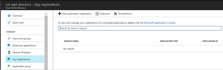
Select App registrations (Figure 3-4) from the navigation pane, and click New Application Registration from the command bar at the top of the blade.
From the Create application blade (Figure 3-5), supply a name for the application. Choose the application type Web/API and supply the Sign-on URL, which is the address where the sign in response can be posted to the application. If you are using the OpenID Connect middleware for aspnetcore, the address will end with /signin-oidc and the middleware knows to look for responses arriving with that path.
Click Create to register the application.
Select App registrations from the navigation pane for the directory. The new application will be listed in the blade.
Select your application by clicking it. From here you can customize additional settings such as the following:
Uploading a logo for login branding
Indicating if the application is single or multi-tenant
Managing keys for OAuth scenarios
Controlling consent settings
Granting permissions

Viewing integration endpoints
You can integrate applications with Azure AD through several protocol endpoints including:
![]() WS-Federation metadata and sign-on endpoints
WS-Federation metadata and sign-on endpoints
![]() SAML-P sign-on and sign-out endpoints
SAML-P sign-on and sign-out endpoints
![]() OAuth 2.0 token and authorization endpoints
OAuth 2.0 token and authorization endpoints
![]() Azure AD Graph API endpoint
Azure AD Graph API endpoint

Exam Tip
The graph endpoint exposed in the Azure Portal for Azure AD directories and applications is the Azure AD Graph API, which relates to Azure AD v1 capabilities. This chapter covers the Microsoft Graph API which is the preferred way to integrate, so a different endpoint will be discussed later.
To view the endpoints (Figure 3-6) available to your directory, do the following:
Navigate to the Azure portal accessed via https://portal.azure.com.
Select Azure Active Directory from the navigation panel and navigate to your directory.
Select App registrations from the navigation pane for the directory, and click Endpoints from the command bar.
The endpoints blade (see Figure 3-2) lists protocol endpoints, such as the following:
 https://login.microsoftonline.com/c6cad604-0f11-4c1c-bdc0-44150037bfd9/wsfed https://login.microsoftonline.com/c6cad604-0f11-4c1c-bdc0-44150037bfd9/saml2 https://graph.windows.net/c6cad604-0f11-4c1c-bdc0-44150037bfd9 https://login.microsoftonline.com/c6cad604-0f11-4c1c-bdc0-44150037bfd9/oauth2/token https://login.microsoftonline.com/c6cad604-0f11-4c1c-bdc0-44150037bfd9/oauth2/authorize

Develop apps that use WS-Federation, SAML-P, OpenID Connect and OAuth endpoints
You can integrate your applications for authentication and authorization workflows using WS-Federation, SAML Protocol (SAML-P), OpenID Connect and OAuth 2.0. Azure AD OAuth 2.0 and endpoints support both OpenID Connect and OAuth 2.0 integration for authentication or authorization requests. If your applications require support for WS-Federation or SAML 2.0 protocol you can use those endpoints to achieve the integration. This section discusses integration using these protocols.
Integrating with OpenID Connect
OAuth 2.0 is an authorization protocol, not an authentication protocol. OpenID Connect extends OAuth 2.0 with standard flows for user authentication and session management. Today’s applications typically use OpenID Connect workflows authenticating users from web, JavaScript, or mobile applications (via the browser). OpenID Connect authentication involves the application sending a sign in request to the directory, and receiving a sign in response at the application. The sign in response includes an id token representing proof of authentication, and the application uses this to establish the user session at the application.
To create an aspnetcore application that authenticates users with OpenID Connect, do the following from Visual Studio 2017:
Open Visual Studio 2017 and create a new project based on the ASP.NET Core Web Application project template (Figure 3-7). Select Web Application for the style of application on the second dialog and then click Change Authentication.

FIGURE 3-7 The new ASP.NET Core Web Application dialog
Select Work or School Accounts and enter your Azure AD domain into the textbox provided (if you are signed in, this will also be available in the drop-down list). Click OK to return to the previous dialog, and again click OK to accept the settings and create the project (Figure 3-8).
Visual Studio will register this application with your Azure AD directory, and configure the project with the correct application settings in the appsettings.json file. These settings provide the following key information to the middleware:
Which directory to communicate with (Domain and TenantId).
Which registered application is making the request (ClientId).
Which redirect URI should be provided with the sign in request, so that Azure AD can validate this in its list of approved redirect URIs (built from the CallbackPath).
The base address of the Azure AD instance to send requests to (Instance).
The following settings are found in the web.config for the new project:
"AzureAd": { "Instance": "https://login.microsoftonline.com/",
"Domain": "solaaddirectory.onmicrosoft.com",
"TenantId": "c6cad604-0f11-4c1c-bdc0-44150037bfd9",
"ClientId": "483db32c-f517-495d-a7b5-03d6453c939c",
"CallbackPath": "/signin-oidc"
},Navigate to your Azure AD directory (Figure 3-9) at the Azure portal and view the App registrations. Select your new application to view its properties. The properties show the App ID URI used to uniquely identify your application at the directory, and the home page URL used to send protocol responses post sign in.


When you run the new project from Visual Studio you will see a workflow like this:
A user navigates to the application.
When the user browses to a protected page or selects Login, the application redirects anonymous users to sign in at Azure AD, sending an OpenID Connect sign in request to the OAuth endpoint.
The user is presented with a login page, unless she has previously signed in and established a user session at the Azure AD tenant.
When authenticated, an OpenID Connect response is returned via HTTP POST to the application URL, and this response includes an id token showing proof of user authentication.
The application processes this response, using the configured middleware that supports OpenID Connect protocol, and verifies the token is signed by the specified trusted issuer (your Azure AD tenant), onfirming that the token is still valid.
The application can optionally use claims in the token to personalize the application experience for the logged in user.
The application can also optionally query Azure AD for groups for authorization purposes.
Integrating with OAuth
OAuth 2.0 is an authorization protocol that is typically used for delegated authorization scenarios where user consent is required to access resources, and for access token requests. The desired response from an OAuth 2.0 authorization request is an access token, which is typically used to call APIs protecting resources.
Before an application can request tokens, it must be registered with the Azure AD tenant and have both a client id and secret (key) that can be used to make OAuth requests on behalf of the application.
To generate a secret for an application, complete the following steps:
Navigate to the directory from the Azure portal accessed via https://portal.azure.com.
Click App registrations in the navigation pane, and select the application you want to enable for token requests via OAuth.
Select Keys in the navigation pane. Provide a friendly name for the key and select a duration for the key to be valid (Figure 3-10).
Click Save on the command bar and the value for the key appears.
Copy the key somewhere safe; it will not be presented again.
You can now use the client id and secret (key) to perform OAuth token requests from your application.

A later section, “Query the Graph API,” covers an example of an OAuth token request authorizing an application to use the Graph API.
Integrating with WS-Federation
WS-Federation is an identity protocol used for browser-based applications for user authentication. To create a new ASP.NET MVC application that integrates with the WS-Federation endpoint there are a number of custom coding steps that are required since the templates do not support this directly. Those steps are discussed at the following reference: https://github.com/Azure-Samples/active-directory-dotnet-webapp-wsfederation.
A few key points to call out about the setup for WS-Federation are as follows:
When you create a new project using Visual Studio (for example, based on the ASP.NET Web Application project template) you will select MVC for the style of application on the second dialog and leave No Authentication as the authentication option for the template (Figure 3-11). If you choose other authentication options, the generated code will always use OpenID Connect as the protocol, and this will not work for WS-Federation or other protocols.

FIGURE 3-11 The new ASP.NET Web Application dialog with no authentication option selected
You will have to add code per the above reference to communicate using WS-Federation protocol and set up the application settings required to match your Azure AD setup for the application.
You will register an Azure AD application following the steps shown earlier in this skill. Here is an example for a WS-Federation application setup (Figure 3-12).
The details for connecting an MVC application with the registered Azure AD application for WS-Federation are covered in the reference. It shows you how to setup the OWIN middleware for WS-Federation: WsFederationAuthenticationMiddleware. In addition to following those steps, note the following:
Ensure that the App ID URI matches the wtrealm parameter that will be passed in the WS-Federation request from the client application.
Ensure SSL is enabled for your application.
Ensure that the Home page URL is an HTTPS endpoint and matches the application SSL path.

When you run a WS-Federation client you will see the following workflow:
A user navigates to the application.
When the user browses to a protected page or selects Login, the application redirects anonymous users to sign in at Azure AD, sending a WS-Federation protocol request that indicates the application URI for the realm parameter. The URI matches the App ID URI shown in the registered application settings.
The request is sent to the tenant WS-Federation endpoint.
The user is presented with a login page, unless she has previously signed in and established a user session at the Azure AD tenant.
When authenticated, a WS-Federation response is returned via HTTP POST to the application URL - and this response includes a SAML token showing proof of user authentication.
The application processes this response, using the configured OWIN middleware that supports WS-Federation, and verifies the token is signed by the specified trusted issuer (your Azure AD tenant), and confirms that the token is still valid.
The application can optionally use claims in the token to personalize the application experience for the logged in user.
The application can optionally query Azure AD for groups for authorization purposes.
Integrating with SAML-P
SAML 2.0 Protocol (SAML-P) can be used like WS-Federation to support user authentication to browser-based applications. For example, SAML-P integration with Azure AD might follow steps like this:
A user navigates to your application.
Your application redirects anonymous users to authenticate at Azure AD, sending a SAML-P request that indicates the application URI for the ConsumerServiceURL element in the request.
The request is sent to your tenant SAML2 sign in endpoint.
The user is presented with a login page, unless she has previously signed in and established a user session at the Azure AD tenant.
When authenticated, a SAML-P response is returned via HTTP POST to the application URL. The URL to use is specified in the single sign-on settings as the Reply URL. This response contains a SAML token.
The application processes this response, verifies the token is signed by a trusted issuer (Azure AD), and confirms that the token is still valid.
The application can optionally use claims in the token to personalize the application experience for the logged in user.
The application can optionally query Azure AD for groups for authorization purposes.
Query the directory using Microsoft Graph API, MFA and MFA API
Beyond authentication and authorization workflows for your applications, you can also interact with the Microsoft Graph API to manage users and request information about users, and integrate multi-factor authentication scenarios into your solutions. This section discusses those capabilities.
Query the Microsoft Graph API
Using the Microsoft Graph API, you can interact with your Azure AD tenant to manage users, groups, and more. If the application is limited to read access only, query activity will be allowed. With read and write access, the application can perform additional management activities:
![]() Add, update, and delete users and groups
Add, update, and delete users and groups
![]() Find users
Find users
![]() Request a user’s group and role membership
Request a user’s group and role membership
![]() Manage group membership
Manage group membership
![]() Create applications
Create applications
![]() Query and create directory properties
Query and create directory properties
Exam Tip
The Microsoft Graph API is accessible via the Azure AD v2 endpoint. The Azure AD v2 endpoint is an evolution of the Azure AD v1 endpoint that modernizes some of the protocol payloads, allows you to use a single endpoint for both Azure AD and Microsoft Account users, and also adds other features. At the time of this writing, the only way to use the Azure AD v2 endpoint is to register applications at the new Microsoft Application Registry at https://apps.dev.microsoft.com. For more details on this see: https://docs.microsoft.com/en-us/azure/active-directory/develop/active-directory-appmodel-v2-overview.
Before you can interact with the Microsoft Graph API programmatically, you must create an application with the Microsoft Application Registry as follows (Figure 3-13):
Navigate to the Microsoft Application Registry accessed via https://apps.dev.microsoft.com.
Click Add an app, and from the app registration page enter a friendly name for your application and supply your contact email for administering the applications. You can optionally select the Guided Setup checkbox for a walkthrough to complete additional settings. Click to create the application.
If you do not select the guided setup, you will see the registration details for your new application and be able to view and manage those details, for example:
View the application id (a GUID) identifying your application.
Generate a password or set up a key pair for the application to support token requests.
Supply web application integration details such as redirect URL and single sign-out URL.
Supply mobile application integration details such as redirect URI.
Set any delegated or application permissions that the application requires.
Provide other application customization details that are relevant during sign in such as the logo, home page URL, terms of service URL, and privacy statement URL.

An application can query the Microsoft Graph API in a few ways:
![]() The application can directly query the graph API with the application id and secret, to access information that the application has direct access to (without user consent being required).
The application can directly query the graph API with the application id and secret, to access information that the application has direct access to (without user consent being required).
![]() The application can request information about the user through delegated permissions, which implies that the user must first authenticate to the application, grant consent (or at least have consent automatically granted at the administrative level), and then make requests on behalf of that user.
The application can request information about the user through delegated permissions, which implies that the user must first authenticate to the application, grant consent (or at least have consent automatically granted at the administrative level), and then make requests on behalf of that user.
To set up a web application to support user authentication, consent and delegated permissions to user information exposed via the Graph API:
Create an application password. Click Generate New Password from the Application secrets section. In the dialog presented save the generated password somewhere safe as it will not be presented again (Figure 3-14).
From Platforms section, select Add Platform and select Web. Provide the web application sign in URL and for single sign-out scenarios you can optionally provide the application sign out URL (Figure 3-15).
By default, the Microsoft Graph Permissions will have delegated permissions for User.Read selected. You may choose to change the delegated permissions, or add application permissions, based on the type of requests your application may make to the Graph API.


Working with MFA
Multi-factor authentication (MFA) requires that users provide more than one verification method during the authentication process, including two or more of the following:
![]() A password (something you know)
A password (something you know)
![]() An email account or phone (something you have)
An email account or phone (something you have)
![]() Biometric input like a thumbprint (something you are)
Biometric input like a thumbprint (something you are)
Azure Multi-Factor Authentication (MFA) is the Microsoft solution for two-step verification workflows that can work with phone, text messages or mobile app verification methods.
You can enable MFA for users in your directory by doing the following:
Navigate to the Azure portal accessed via https://portal.azure.com.
Click New and select Security + Identity, then select Multi-Factor Authentication from the list of choices (Figure 3-16).
You will see a link that will take you to the (old) management portal. Click Go to navigate to that portal (Figure 3-17).
From the (old) management portal select your directory and click the Configure tab (Figure 3-18).
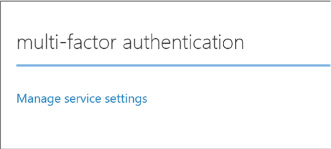
Scroll down to the multi-factor authentication section and click Manage service settings. You will navigate to another portal where you can configure your multi-factor authentication service settings (Figure 3-19).
From the multi-factor authentication portal, select the service settings tab. You can optionally customize settings for the following:
App passwords
Trusted IPs to bypass multi-factor authentication
Enabled multi-factor verification options such as call or text to phone, mobile notifications or mobile apps
Device remember-me settings
Select the users tab. From here you can select users and enable multi-factor authentication (Figure 3-20). Select a user from your directory who does not yet have multi-factor enabled, and click Enable from the action pane to the right.


Users with multi-factor authentication enabled will be prompted to set up their multi-factor authentication settings during their next login. The login workflow will follow these steps:
First, the user is taken to the directory login where they are prompted to login with their username and password.
Once authenticated, they are presented with a request to set up their multi-factor settings (Figure 3-21).
If the user has not yet supplied their email address or phone number for multi-factor authentication, they will be asked to provide this information now. In addition, they will be taken through the process of verifying this information to ensure they can be used safely for future multi-factor authentication workflows.


Exam Tip
Azure Multi-Factor Authentication is included inAzure Active Directory Premium plans and Enterprise Mobility + Security plans, and can be deployed either in the cloud or on-premises. See the following documentation for the full details about Microsoft’s MFA solution: https://docs.microsoft.com/en-us/azure/multi-factor-authentication.
Work with the MFA API
You may choose to integrate multi-factor authentication directly into your applications. This can be done by using the Multi-factor Authentication Software Development Kit (SDK), which provides an API for interacting with Azure MFA from your application.
In order to use these MFA APIs you must first create a Multi-factor Authentication Provider from the Azure portal following these steps:
Navigate to the Azure portal accessed via https://portal.azure.com.
Click New and select Security + Identity, then select Multi-Factor Authentication from the list of choices. You will see a link that will take you to the (old) management portal (Figure 3-22). Click Go to navigate to that portal.
Select Active Directory from the navigation pane and select the Multi-factor Auth Providers tab.
Create a new provider and set these values (Figure 3-23):
Name for the provider.
Usage model, choosing between Per Enabled User or Per Authentication.
Associate the provider with one of your directories.
Click Create to create the new multi-factor authentication provider (Figure 3-24). You will see it in the list of the providers once it’s created.
To manage settings for the multi-factor authentication provider, select it and click Manage from the command bar below. You will be taken to the Azure Multi-Factor Authentication portal (Figure 3-25).
Select Downloads to view the available MFA SDK downloads and choose the one for your development environment for download.


Exam Tip
You can only associate one multi-factor authentication provider to a directory.
Skill 3.2: Develop apps that use Azure AD B2C and Azure AD B2B
Azure AD supports user sign-in with social identity providers such as Google and Facebook as part of Azure AD B2C. Azure AD also enables access to applications from external partners as part of Azure B2B collaboration. This section discusses these features.
This skill covers how to:
![]() Design and implement .NET MVC, Web API, and Windows desktop apps that leverage social identity provider authentication
Design and implement .NET MVC, Web API, and Windows desktop apps that leverage social identity provider authentication
![]() Leverage Azure AD B2B to design and implement applications that support partner-managed identities and enforce multi-factor authentication
Leverage Azure AD B2B to design and implement applications that support partner-managed identities and enforce multi-factor authentication
Design and implement apps that leverage social identity provider authentication
Azure AD B2C makes it possible for users of your applications to authenticate with social identity providers, enterprise accounts using open standards, and local accounts where users are managed by Azure AD. Fundamentally this means that the user signs in at the identity provider, and therefore, credentials are managed by the identity provider.
Figure 3-26 illustrates the workflow assuming OpenID Connect protocol for communication between a web application and the Azure AD B2C tenant. The user navigates to the application to login (1) and is redirected to Azure AD with an OpenID Connect sign in request (2). Azure AD redirects the user to the third party identity provider (3) with the protocol that is established for communication between Azure AD and that provider (it may not be OpenID Connect). If the user does not yet have an active session at the identity provider, they are typically presented with a login page to enter credentials (4), and upon successful authentication (5), the identity provider issues a protocol response and sets up the user session (6) possibly in the form of an SSO session cookie. The response is posted to Azure AD (7) and validated. Upon successful validation of the response (and user identity) Azure AD establishes a user session (SSO session cookie) and issues an OpenID Connect response to the calling web app (8). This response is posted to the web app (9) and validated to establish the user session at the web app (10).

FIGURE 3-26 The high-level workflow for user sign-in to an external identity provider via Azure AD B2C
There are a few important things to point out about this workflow:
![]() Applications need not be aware of the identity provider where the user signs in, since the application trusts the response from Azure AD.
Applications need not be aware of the identity provider where the user signs in, since the application trusts the response from Azure AD.
![]() The trust relationships are between applications and Azure AD, and between Azure AD and the identity provider(s) that are configured (see Figure 3-27).
The trust relationships are between applications and Azure AD, and between Azure AD and the identity provider(s) that are configured (see Figure 3-27).
![]() The protocols to be used between Azure AD and identity provider can vary per identity provider. This has no relationship to how the application communicates with Azure AD.
The protocols to be used between Azure AD and identity provider can vary per identity provider. This has no relationship to how the application communicates with Azure AD.

FIGURE 3-27 Trust relationships between Applications and Azure AD, and between Azure AD and external identity providers
This section covers how to set up Azure AD B2C to enable users to login with their preferred social identity provider such as Microsoft Account, Facebook, Google+, Amazon or Linked In.
Create an Azure AD B2C tenant
To create a new Azure AD B2C tenant follow these steps:
Navigate to the Azure portal accessed via https://portal.azure.com.
Click New and select Security + Identity, then select Azure Active Directory B2C from the list of choices (Figure 3-28).
Click Create from the Azure Active Directory B2C blade.
You may be prompted to switch to a directory with a subscription attached. If so, click Switch directories and select the correct subscription where you want to create the new B2C tenant. You may also have to repeat steps 1-3.
From the Create new B2C tenant or Link to existing tenant blade, select Create a new Azure AD B2C tenant (Figure 3-29).
Enter a name for the organization, a domain name, and select the country or region for the new tenant.
You can navigate to your directory by clicking the link supplied in the create blade, after the directory is created. Or, you can navigate to More Services from the navigation menu and type Azure AD to filter the list and find Azure AD B2C, then select it (Figure 3-30).
Your tenant will appear in the B2C Tenant dashboard and may show a notification indicating that it is not attached to a subscription. If this happens, switch directories again, select your subscription from the list, and repeat steps 1-3. At step 4 select Link to existing tenant and choose your tenant. This will remove the warning.
Repeat step 6 to return to your Azure B2C tenant dashboard and click the tenant settings component. From here you will be able to manage your tenant settings.


Register an application
A given solution may have one or more applications that will integrate with Azure AD B2C. Integration requires an application be registered with the B2C tenant. When you register an application, you can configure how the application will integrate with the tenant, for example:
![]() Indicate if the application is a web or API application, or a native application
Indicate if the application is a web or API application, or a native application
![]() Indicate if OpenID Connect will be used to authenticate users interactively
Indicate if OpenID Connect will be used to authenticate users interactively
![]() Indicate any required redirect URLs or URIs
Indicate any required redirect URLs or URIs
Follow these steps to register a web application:
Navigate to your B2C tenant settings (Figure 3-31) as described in the previous section
Select Applications and click Add from the command bar
In the New application blade, provide the following settings (Figure 3-32):
Enter a name for the application
Select Yes for Web App / Web API
Select Yes for Allow implicit flow
Provide a reply URL authentication responses should be posted
An application ID is created for the application once you create it (Figure 3-33). Select the application from the applications list and you can review its settings including this new application ID.


Now you can set up your application with the following settings:
![]() Configure any external identity providers to be supported for sign in
Configure any external identity providers to be supported for sign in
![]() Manage user attributes
Manage user attributes
![]() Manage users and groups
Manage users and groups
![]() Manage policies
Manage policies
Configure identity providers
You may want to give your users a choice between one or more external identity providers to sign in. Azure AD supports a pre-defined set of well-known social identity providers to choose from (Figure 3-34).
To configure an external identity provider, follow these steps:
Navigate to your directory settings as discussed previously.
Select identity providers from the navigation pane.
Enter a name for the identity provider, something that matches the provider you will configure such as “google” or “facebook.”
Select the identity provider to configure and click OK.
Set up the identity provider in the final tab. Based on the selected identity provider, you will be presented with required settings that typically include a client id and secret for the provider. You must have previously set up an application with the identity provider, in order to have the required settings for this configuration. Once you have entered the required settings, click OK (see Figure 3-35).
Click Create to complete the configuration of the identity provider. You will see your new provider listed in the identity providers blade.


Configuring policies
There are several policies you can configure for your Azure AD B2C tenant. These policies enable features and govern the user experience for the following scenarios:
![]() Sign-up
Sign-up
![]() Sign-in
Sign-in
![]() Profile editing
Profile editing
![]() Password reset
Password reset
These policies all provide default UI templates but allow for overriding those templates for further customization. You can also determine which identity provider shall be supported, support for multi-factor authentication, and control over which claims shall be returned with the id token post authentication. For sign-up, you can also configure which profile attributes you want to collect for the user.
Leverage Azure AD B2B to design and implement applications that support partner-managed identities and enforce multi-factor authentication
Azure AD B2B collaboration capabilities enable organizations using Azure AD to allow users from other organizations, with or without Azure AD, to have limited access to documents, resources and applications.
From your Azure AD tenant you can:
![]() Set up single sign-on to enterprise applications such as Salesforce and Dropbox through Azure AD
Set up single sign-on to enterprise applications such as Salesforce and Dropbox through Azure AD
![]() Support user authentication via Azure AD for your own applications
Support user authentication via Azure AD for your own applications
![]() Enable access to these applications to users outside of your directory
Enable access to these applications to users outside of your directory
![]() Enforce multi-factor authentication for these users
Enforce multi-factor authentication for these users
Skill 3.3: Manage Secrets using Azure Key Vault
Cloud applications typically need a safe workflow for secret management. Azure Key Vault provides a secure service for Azure applications and services for:
![]() Encrypting storage account keys, data encryption keys, certificates, passwords and other keys and secrets
Encrypting storage account keys, data encryption keys, certificates, passwords and other keys and secrets
![]() Protecting those keys using hardware security modules (HSMs)
Protecting those keys using hardware security modules (HSMs)
Exam Tip
Azure Key Vault supports importing and generating keys in HSMs. This means that keys are processed in FIPS 140-2 Level 2 validated HSMs.
Developers can easily create keys to support development efforts, while administrators are able to grant or revoke access to keys as needed. This section covers how to manage secrets with Azure Key Vault.
This skill covers how to:
![]() Configure Azure Key Vault
Configure Azure Key Vault
![]() Manage access, including tenants
Manage access, including tenants
![]() Implement HSM protected keys
Implement HSM protected keys
![]() Manage service limits
Manage service limits
![]() Implement logging
Implement logging
![]() Implement key rotation
Implement key rotation
Configure Azure Key Vault
You can create one or more key vault in a subscription, according to your needs for management isolation. To create a new key vault, follow these steps:
Navigate to the Azure portal accessed via https://portal.azure.com.
Click New and select Security + Identity, then select Key Vault from the list of choices (Figure 3-36).
From the Create key vault blade, enter the following values (Figure 3-37):
A name for the key vault
Choose the subscription
Create or choose a resource group
A location
Choose a pricing tier - primarily based on your requirements for HSM
Set up policies for user access to keys, secrets and certificates
Optionally grant access for Azure Virtual Machines, Azure Resource Manager or Azure Disk Encryption
Click Create to create the key vault.


Manage access, including tenants
There are two ways to access the key vault - through the management plane or the data plane. The management plane exposes an interface for managing the key vault settings and policies, and the data plane exposes an interface for managing the actual secrets and policies related directly to managing those secrets. You can set up policies that control access through each of these planes, granting users, applications or devices access to specific functionality (service principals). These service principals must be associated with the same Azure AD tenant as the key vault.
To create policies for your key vault, navigate to the key vault Overview and do the following (Figure 3-38):
Select Access policies from the navigation pane.
Select Add new from the Access policies blade.
Select Configure from template and select Key, Secret & Certificate Management. This will initialize a set of permissions based on the template, which you can later adjust.
Click Select a principal and enter a username, application id or device id from your directory.
Review key permissions selected by the template-modify them as needed according to the requirements for the principal selected (Figure 3-39).
Review secret permissions selected by the template, modify them as needed according to the requirements for the principal selected (Figure 3-40).
Review certificate permissions selected by the template, and modify them as needed according to the requirements for the principal selected (Figure 3-41).
Click OK to save the policy settings (Figure 3-42).
From the key vault blade, click Save from the command bar to commit the changes.


In addition to granting access to service principals, you can also set advance access policies to allow access to Azure Virtual Machines, Azure Resource Manager, or Azure Disk Encryption as follows (Figure 3-43):
Select the Advanced access policies tab from the navigation pane.
Enable access by Azure Virtual Machines, Azure Resource Manager or Azure Disk Encryption as appropriate.

Exam Tip
Your key vault is initially associated with the default Azure AD tenant for the subscription it belongs to. You may move the key vault to a new subscription, or simply need to associate the key vault to another Azure AD tenant. You can change this tenant association using PowerShell command as described by this reference: https://docs.microsoft.com/en-us/azure/key-vault/key-vault-subscription-move-fix.
Implement HSM protected keys
If you create a key vault based on a premium subscription, you will be able to generate, store and manage Hardware Security Module (HSM) protected keys. To create an HSM protected key follow these steps:
Navigate to the Azure portal accessed via https://portal.azure.com.
Navigate to More Services from the navigation menu and type key vault to filter the list and find Key Vaults and then select it.
From the Key vaults blade, select a previously created key vault that supports HSM.
Select the Keys tab from the navigation pane, and click Add from the command bar.
From the Create key blade, enter the following information (Figure 3-44):
For Options, select Generate. You can also upload a key or restore a key from a backup.
Provide a name for the key.
For key type, select HSM protected key.
Optionally provide an activation and expiry date for the key. Otherwise there is no set expiry.
Indicate if the key should be enabled now.
Click Create to complete the creation of the key.

Exam Tip
Software keys (not protected by HSM) can be later exported from the key vault. HSM keys, on the other hand, can never be exported. In addition, all cryptographic operations using HSM keys are always performed within the HSM boundary.
![]() All REST API requests including failed, unauthenticated or unauthorized requests
All REST API requests including failed, unauthenticated or unauthorized requests
![]() Key vault operations to create, delete or change settings
Key vault operations to create, delete or change settings
![]() Operations that involve keys, secrets, and certificates in the key vault
Operations that involve keys, secrets, and certificates in the key vault
Logs are saved to an Azure storage account of your choice, in a new container (generated for you) named insights-logs-auditevent. To set up diagnostic logging, follow these steps:
Navigate to the Azure portal accessed via https://portal.azure.com.
Navigate to More Services from the navigation menu and type “key vault “ to filter the list and find Key Vaults, and then select it.
From the Key vaults blade, select the key vault to enable logging for.
From the Key vault blade, select the Diagnostics logs tab from the navigation pane.
From the Diagnostics logs blade, select the Turn on diagnostics link.
From the Diagnostics settings blade enter the following settings (Figure 3-45):
Provide a name for the diagnostics settings.
One of the following optional settings must be chosen:
Select Archive to a storage account and configure a storage account where the logs should be stored. This storage account must be previously created using the Resource Manager deployment model (not Classic), and a new container for key vault logs will be created in this storage account. Optionally select Stream to an event hub if you want logs to be part of your holistic log streaming solution. Optionally select Send logs to Log Analytics and configure an OMS workspace for the logs to be sent to.Select AuditEvent (the only category for key vault logging) and configure retention preferences for storage. If you configure retention settings, older logs will be deleted.
Click Save from the command bar to save these diagnostics settings.
You will now be able to see logs from the Diagnostics output.

Exam Tip
You can use the same storage account to collect logs for multiple key vaults. You can also seamlessly integrate key vault logs with log analytics, provided by Operations Management Services (OMS).
Implement key rotation
The beauty of working with a key vault is the ability to roll keys without impact to applications. Applications do not hold on to key material, and they reference keys indirectly through the key vault. Keys are updated without affecting this reference and so application configuration updates are no longer necessary when keys are updated. This opens the door to simplified key update procedures and the ability to embrace regular or ad-hoc key rotation schedules.
Each key, secret or certificate stored in Azure Key Vault can have one or more versions associated. The first version is created when you first create the key. Subsequent versions can be created through the Azure Portal, through key vault management interfaces, or through automation procedures.
To rotate a key from the Azure Portal, navigate to the key vault and follow these steps:
Select the Keys tab from the navigation pane.
Select the key to rotate.
From the key’s Versions blade (Figure 3-46), you will see the first version of the key that was created.
Click New Version from the command bar and you will be presented with the Create A Key Blade where you can generate or upload a new key to be associated with the same key name. You can choose the type of key (Software key or HSM protected key) and optionally indicate an activation and expiry timeframe. Click Create to replace the key.
You will now see two versions of the key on the Versions blade (Figure 3-47). Applications querying for the key will now retrieve the new version.


This key rotation procedure works similarly for secrets and certificates. Applications will now retrieve the newer version when contacting the key vault for the specified key.
Skill 3.4: Design and implement a messaging strategy
MicrosoftAzure provides a robust set of hosted infrastructure services that provides multi-tenant services for communications between applications. Variously, these supports service publishing, messaging, and the distribution of events at scale. The services we focus on in this section include:
![]() Azure Relay Expose secure endpoints for synchronous calls to service endpoints across a network boundary, for example to expose on-premises resources to a remote client without requiring a VPN.
Azure Relay Expose secure endpoints for synchronous calls to service endpoints across a network boundary, for example to expose on-premises resources to a remote client without requiring a VPN.
![]() Azure Service Bus Queues Implement brokered messaging patterns where the message sender can deliver a message even if the receiver is temporarily offline.
Azure Service Bus Queues Implement brokered messaging patterns where the message sender can deliver a message even if the receiver is temporarily offline.
![]() Azure Service Bus Topics and subscriptions Implement brokered messaging patterns for publish and subscribe where messages can be received by more than one receiver (subscriber), and conditions can be applied to message delivery.
Azure Service Bus Topics and subscriptions Implement brokered messaging patterns for publish and subscribe where messages can be received by more than one receiver (subscriber), and conditions can be applied to message delivery.
![]() Azure Event Hubs Implement scenarios that support high-volume message ingest and where receivers can pull messages to perform processing at scale.
Azure Event Hubs Implement scenarios that support high-volume message ingest and where receivers can pull messages to perform processing at scale.
![]() Azure Notification Hubs Implement scenarios for sending app-centric push notifications to mobile devices.
Azure Notification Hubs Implement scenarios for sending app-centric push notifications to mobile devices.
Relays are used for relayed, synchronous messaging. The remaining scenarios are a form of brokered, asynchronous messaging patterns. In this section, you learn how to implement, scale and monitor each Service Bus resource.
More Info: Service Bus Resources and Samples
See these references for a collection of overviews, tutorials, and samples related to Service Bus:
![]() Azure Relay https://docs.microsoft.com/en-us/azure/service-bus-relay/
Azure Relay https://docs.microsoft.com/en-us/azure/service-bus-relay/
![]() Service Bus Messaging https://docs.microsoft.com/en-us/azure/service-bus-messaging/
Service Bus Messaging https://docs.microsoft.com/en-us/azure/service-bus-messaging/
![]() Event Hubs https://docs.microsoft.com/en-us/azure/event-hubs/
Event Hubs https://docs.microsoft.com/en-us/azure/event-hubs/
![]() Notification Hubs https://docs.microsoft.com/en-us/azure/notification-hubs/
Notification Hubs https://docs.microsoft.com/en-us/azure/notification-hubs/
This skill covers how to:
![]() Develop and scale messaging solutions using Service Bus queues, topics, relays and Notification Hubs
Develop and scale messaging solutions using Service Bus queues, topics, relays and Notification Hubs
![]() Scale and monitor messaging
Scale and monitor messaging
![]() Determine when to use Event Hubs, Service Bus, IoT Hub, Stream Analytics and Notification Hubs
Determine when to use Event Hubs, Service Bus, IoT Hub, Stream Analytics and Notification Hubs
Develop and scale messaging solutions using Service Bus queues, topics, relays and Notification Hubs
A namespace is a container for Service Bus resources including queues, topics, Relays, Notification Hubs, and Event Hubs. With namespaces, you can group resources of the same type into a single namespace, and you can choose to further separate resources according to management and scale requirements. You don’t create a namespace directly, instead you will typically create a namespace as a first step in deploying a Service Bus queue, topic, Relay, Notification Hubs or Event Hubs instance. Once you have a namespace for a particular service, you can add other service instances of the same type to it (a Service Bus namespace supports the addition of queues and topics, so a Notification Hubs namespace supports only Notification Hubs instances). You can also manage access policies and adjust the pricing tier (for scaling purposes), both of which apply to all the services in the namespace.
The steps for creating a Service Bus namespace are as follows:
In the Azure Portal, select + New, then search for the type of namespace you want to create: Service Bus, Relay, Notification Hubs or Event Hubs.
Select Create.
In the Create namespace blade (Figure 3-48), enter a unique prefix for the namespace name.
Choose your Azure Subscription, Resource group and Location.
Select Create to deploy the namespace.

Selecting a protocol for messaging
By default, Service Bus supports several communication protocols. Table 3-1 lists the protocol options and required ports.
TABLE 3-1 Service Bus protocols and ports
Protocol |
PORTS |
Description |
SBMP |
9350-9354 (for relay) 9354 (for brokered messaging) |
Service Bus Messaging Protocol (SBMP), is a proprietary SOAP-based protocol that typically relies on WCF under the covers to implement messaging with between applications through Service Bus. Relay services use this protocol by default when non-HTTP relay bindings are chosen. environment is set to use HTTP. This protocol is being phased out in favor of AMQP. |
HTTP |
80, 443 |
HTTP protocol can be used for relay services when one of the HTTP relay bindings are selected and the Service Bus environment is set to use HTTP connectivity. The brokered messaging client library uses this if you do not specify AMQP protocol and set the Service Bus environment to HTTP as follows: ServiceBusEnvironment.SystemConnectivity.Mode = ConnectivityMode.Http; |
AMQP |
5671, 5672 |
Advanced Message Queuing Protocol (AMQP) is a modern, cross-platform asynchronous messaging standard. The brokered messaging client library uses this protocol if the connection string indicates TransportType of Amqp. |
WebSockets |
80, 443 |
WebSockets provide a standards compliant way to establish bi-directional communication channels, and can be used for Service Bus queues, topics and the Relay. |
Exam Tip
Connectivity issues are common for on-premises environments that disable ports other than 80 and 443. For this reason, it is still often necessary for portability to use HTTP protocol for brokered messaging.
Introducing the Azure Relay
The Azure Relay service supports applications that need to communicate by providing an Azure hosted rendezvous endpoint where listeners (the server process that exposes functionality) and senders (the application that consumes the server process functionality) can connect, and then the Azure Relay service itself takes care of relaying the data between the two cloud-side connections. The Azure Relay has two distinct ways that you can choose from to securely achieve this form of connectivity:
![]() Hybrid Connections With Hybrid Connections your applications communicate by establishing Web Sockets connections with relay endpoints. This approach is standards based, meaning it is useable from almost any platform containing basic Web Socket capabilities.
Hybrid Connections With Hybrid Connections your applications communicate by establishing Web Sockets connections with relay endpoints. This approach is standards based, meaning it is useable from almost any platform containing basic Web Socket capabilities.
![]() WCF Relays With WCF relays, your applications use Windows Communication Foundation to enable communication across relay endpoints. This approach is only useable with applications leveraging WCF and .NET.
WCF Relays With WCF relays, your applications use Windows Communication Foundation to enable communication across relay endpoints. This approach is only useable with applications leveraging WCF and .NET.
Using Hybrid Connections
At a high level, to use Hybrid Connections involves these steps:
Deploy an Azure Relay namespace
Deploy a Hybrid Connection within the namespace
Retrieve the connection configuration (connection details and credentials)
Create a listener application that uses the configuration to provide service-side functionality
Create a sender application that uses the configuration to communicate with the listener
Run the applications
The following sections walk through creating a simple solution where the listener simply echoes the text sent from the sender. The sender itself takes input typed from the user in a console application and sends it to the listener by way of a Hybrid Connection.
DEPLOY AN AZURE RELAY NAMESPACE
The following steps are needed to deploy a new Azure Relay namespace:
In the Azure Portal, select + NEW and then search for “Relay”. Select the item labeled Relay by Microsoft.
In the Create namespace blade, enter a unique prefix for the namespace name.
Choose your Azure Subscription, Resource group and Location.
Select Create to deploy the namespace.
DEPLOY A HYBRID CONNECTION
The following steps are needed to deploy a new Hybrid Connection within the Azure Relay namespace:
Using the Portal, navigate to the blade of your deployed Relay namespace.
Select + Hybrid Connection from the command bar.
On the Create Hybrid Connection blade, enter a name for your new Hybrid Connection.
Select Create.
RETRIEVE THE CONNECTION CONFIGURATION
Your applications will need at minimum the following configuration in order to communicate with the Hybrid Connection:
![]() Namespace URI
Namespace URI
![]() Hybrid Connection Name
Hybrid Connection Name
![]() Shared access policy name
Shared access policy name
![]() Shared access policy key
Shared access policy key
Follow these steps to retrieve these values for use in your listener and sender applications:
Using the Portal, navigate to the blade of your deployed Relay namespace.
From the menu, select Shared access policies to retrieve the policies available at the namespace level.
In the list of policies, select a policy. For example, by default the RootManageSharedAccessKey policy is available.
On the Policy blade, take note of the policy name and the value of the Primary key. Also note the connection string values you can use with SDKs that support these as inputs (Figure 3-49).
Close the Policy blade.
From the menu, select Hybrid Connections.
In the listing, select your deployed Hybrid Connection.
From the Essentials panel, take note of the value for Namespace. This is the namespace name.
Also, take note of the Hybrid Connection URL (Figure 3-50). It is of the form https://<namespace>.servicebus.windows.net/<hybridconnectionname>
You can get the name of your Hybrid Connection either from the title of the blade, or by looking at the Hybrid Connection URL and copying the value after the slash (/).


CREATE A LISTENER APPLICATION
Follow these steps to create simple listener application that echoes any text transmitted by a sender application:
Launch Visual Studio.
Select File, New, Project and select Visual C# from the tree under Templates, and then the Console App (.NET Framework) template.
Provide the name and location of your choice.
Select OK.
In Solution Explorer, right click the new project and select Manage NuGet Packages.
In the document that appears, select Browse.
Search for “Microsoft.Azure.Relay” and then select the Microsoft Azure Relay item in the list (Figure 3-51).
Select Install to begin the installation and follow the prompts.
Open program.cs.
Replace the using statements at the top of the document with the following:
using System;
using System.IO;
using System.Threading;
using System.Threading.Tasks;
using Microsoft.Azure.Relay;Replace the Program class with the following:
class Program
{
private const string RelayNamespace = "<namespace>.servicebus.windows.net";
private const string ConnectionName = "<hybridconnectionname>";
private const string KeyName = "<sharedaccesskeyname> ";
private const string Key = "<sharedaccesskeyvalue>";
static void Main(string[] args)
{
RunAsync().GetAwaiter().GetResult();
}
private static async void ProcessMessagesOnConnection(
HybridConnectionStream relayConnection,
CancellationTokenSource cts)
{
Console.WriteLine("New session");
// The connection is a fully bidrectional stream, enabling the Listener
to echo the text from the Sender.
var reader = new StreamReader(relayConnection);
var writer = new StreamWriter(relayConnection) { AutoFlush = true };
while (!cts.IsCancellationRequested)
{
try
{
// Read a line of input until a newline is encountered
var line = await reader.ReadLineAsync();
if (string.IsNullOrEmpty(line))
{
await relayConnection.ShutdownAsync(cts.Token);
break;
}
Console.WriteLine(line);
// Echo the line back to the client
await writer.WriteLineAsync($"Echo: {line}");
}
catch (IOException)
{
Console.WriteLine("Client closed connection");
break;
}
}
Console.WriteLine("End session");
// Close the connection
await relayConnection.CloseAsync(cts.Token);
}
private static async Task RunAsync()
{
var cts = new CancellationTokenSource();
var tokenProvider =
TokenProvider.CreateSharedAccessSignatureTokenProvider(KeyNa
me, Key);
var listener = new HybridConnectionListener(
new Uri(string.Format("sb://{0}/{1}",
RelayNamespace, ConnectionName)),
tokenProvider);
// Subscribe to the status events
listener.Connecting += (o, e) => { Console.WriteLine("Connecting"); };
listener.Offline += (o, e) => { Console.WriteLine("Offline"); };
listener.Online += (o, e) => { Console.WriteLine("Online"); };
// Establish the control channel to the Azure Relay service
await listener.OpenAsync(cts.Token);
Console.WriteLine("Server listening");
// Providing callback for cancellation token that will close the listener.
cts.Token.Register(() => listener.CloseAsync(CancellationToken.None));
// Start a new thread that will continuously read the console.
new Task(() => Console.In.ReadLineAsync().ContinueWith((s) => {
cts.Cancel(); })).Start();
// Accept the next available, pending connection request.
while (true)
{
var relayConnection = await listener.AcceptConnectionAsync();
if (relayConnection == null)
{
break;
}
ProcessMessagesOnConnection(relayConnection, cts);
}
// Close the listener after we exit the processing loop
await listener.CloseAsync(cts.Token);
}
}In the aforementioned code, replace the values as follows:
<namespace> Your Azure Relay namespace name. <hybridconnectionname> The name of your Hybrid Connection. <sharedaccesskeyname> The name of your Shared Access Key as acquired from the Policy blade in the Portal. <sharedaccesskeyvalue> The value of your Shared Access Key as acquired from the Policy blade in the Portal.

CREATE A SENDER APPLICATION
Next, add another Console Application project that will contain the code for the sender application by following these steps:
In Solution Explorer, right click your solution and select Add, New Project and then choose Console App (.NET Framework).
Provide the name and location of your choice.
Select OK.
In Solution Explorer, right click the new project and select Manage NuGet Packages.
In the document that appears, select Browse.
Search for “Microsoft.Azure.Relay” and then select the Microsoft Azure Relay item in the list.
Select Install to begin the installation and follow the prompts.
Open program.cs.
Replace the using statements at the top of the document with the following:
using System;
using System.IO;
using System.Threading;
using System.Threading.Tasks;
using Microsoft.Azure.Relay;
Replace the Program class with the following:
class Program
{
private const string RelayNamespace = "<namespace>.servicebus.windows.net";
private const string ConnectionName = "<hybridconnectionname>";
private const string KeyName = "<sharedaccesskeyname> ";
private const string Key = "<sharedaccesskeyvalue>";
static void Main(string[] args)
{
RunAsync().GetAwaiter().GetResult();
}
private static async Task RunAsync()
{
Console.WriteLine("Enter lines of text to send to the server with
ENTER");
// Create a new hybrid connection client
var tokenProvider = TokenProvider.CreateSharedAccessSignatureTokenProv
ider(KeyName, Key);
var client = new HybridConnectionClient(new
Uri(String.Format("sb://{0}/{1}", RelayNamespace, ConnectionName)),
tokenProvider);
// Initiate the connection
var relayConnection = await client.CreateConnectionAsync();
var reads = Task.Run(async () => {
var reader = new StreamReader(relayConnection);
var writer = Console.Out;
do
{
// Read a full line of UTF-8 text up to newline
string line = await reader.ReadLineAsync();
// if the string is empty or null, we are done.
if (String.IsNullOrEmpty(line))
break;
// Write to the console
await writer.WriteLineAsync(line);
}
while (true);
});
// Read from the console and write to the hybrid connection
var writes = Task.Run(async () => {
var reader = Console.In;
var writer = new StreamWriter(relayConnection) { AutoFlush = true
};
do
{
// Read a line form the console
string line = await reader.ReadLineAsync();
await writer.WriteLineAsync(line);
if (String.IsNullOrEmpty(line))
break;
}
while (true);
});
await Task.WhenAll(reads, writes);
await relayConnection.CloseAsync(CancellationToken.None);
}In the aforementioned code, replace the values as follows:
<namespace> Your Azure Relay namespace name. <hybridconnectionname> The name of your Hybrid Connection. <sharedaccesskeyname> Tthe name of your Shared Access Key. <sharedaccesskeyvalue> Tthe value of your Shared Access Key.
RUN THE APPLICATIONS
Finally, run the applications to exercise the relay functionality:
Using Solution Explorer, right click your solution and select Set Startup Projects.
In the dialog, select Multiple startup projects.
Set the action to Start for both projects, making sure that your listener is above your sender so that it starts first.
Select OK.
From the Debug menu, select Start without debugging.
On the sender console screen (Figure 3-52), respond to the prompt by typing some text to send to the listener and pressing enter.
Verify in the other console screen (the listener), that the text was received and that it was echoed back to the sender.

Using the WCF Relay
The WCF Relay service is frequently used to expose on-premises resources to remote client applications located in the cloud or across network boundaries, in other words it facilitates hybrid applications. It involves creating a Service Bus namespace for the Relay service, creating shared access policies to secure access to management, and following these high level implementation steps:
Create a service contract defining the messages to be processed by the Relay service.
Create a service implementation for that contract. This implementation includes the code to run when messages are received.
Host the service in any compatible WCF hosting environment, expose an endpoint using one of the available WCF relay bindings, and provide the appropriate credentials for the service listener.
Create a client reference to the relay using typical WCF client channel features, providing the appropriate relay binding and address to the service, with the appropriate credentials for the client sender.
Use the client reference to call methods on the service contract to invoke the service through the Service Bus relay.
The WCF Relay service supports different transport protocols and Web services standards. The choice of protocol and standard is determined by the WCF relay binding selected for service endpoints. The list of bindings supporting these options are as follows:
![]() BasicHttpRelayBinding
BasicHttpRelayBinding
![]() WS2007HttpRelayBinding
WS2007HttpRelayBinding
![]() WebHttpRelayBinding
WebHttpRelayBinding
![]() NetTcpRelayBinding
NetTcpRelayBinding
![]() NetOneWayRelayBinding
NetOneWayRelayBinding
![]() NetEventRelayBinding
NetEventRelayBinding
Clients must select from the available endpoints exposed by the service for compatible communication. HTTP services support two-way calls using SOAP protocol (optionally with extended WS* protocols) or classic HTTP protocol requests (also referred to as REST services). For TCP services, you can use synchronous two-way calls, one-way calls, or one-way event publishing to multiple services.
Exam Tip
The NetTcpRelayBinding relay supports two connection modes: relayed (the default) or hybrid. In hybrid mode, communications are initially relayed, but if possible, a direct socket connection is established between client and service, thus removing the relay from communications for the session.
Deploy a WCF Relay
The following steps are needed to deploy a new WCF Relay within the Azure Relay namespace:
Using the Portal, navigate to the blade of your deployed Relay namespace.
Select + WCF Relay from the command bar.
On the Create WCF Relay blade (Figure 3-53), enter a name for your new WCF Relay.
Select the Relay Type (NetTcp or HTTP).
Select Create.
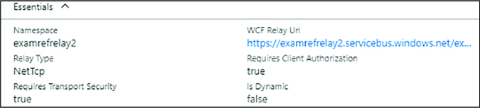
Once deployment completes, select your new WCF Relay from the list (Figure 3-54).
In the Essentials blade, take note of your WCF Relay URL and namespace (Figure 3-55).


Managing relay credentials
WCF Relay credentials are managed on the Shared access policies blade for the namespace as follows:
Make sure you have created a Service Bus namespace as described in the section “Create a Service Bus namespace.”
Navigate to the blade for your Service Bus namespace in the Azure Portal.
From the menu, select Shared access.
To create a new shared access policy for the namespace, select + Add.
Provide a name for the Policy and select what permissions (Manage, Send, Listen) it should have (Figure 3-56).
Select Create.
You can view the Keys after the policy has been created by selecting Shared access polices and then choosing your newly created policy.

CREATING A RELAY AND LISTENER ENDPOINT
After you have created the namespace and noted the listener policy name and key, you can write code to create a relay service endpoint. Here is a simple example, it assumes you have deployed a relay of type NetTcp:
Open Visual Studio and create a new console application.
Add the Microsoft Azure Service Bus NuGet package (WindowsAzure.ServiceBus) to the console application.
Create a WCF service definition to be used as a definition for the relay contract and an implementation for the relay listener service. Add a class file to the project with the following service contract and implementation. Include the using statement at the top of the file:
using System.ServiceModel;
[ServiceContract]
public interface IrelayService
{
[OperationContract]
string EchoMessage(string message);
}
public class RelayService:IrelayService
{
public string EchoMessage(string message)
{
Console.WriteLine(message);
return message;
}
}Host the WCF service in the console application by creating an instance of the WCF ServiceHost for the service. Add an endpoint using NetTcpRelayBinding, passing the name of the Service Bus namespace, policy name, and key. Include the using statements at the top of the file:
using System.ServiceModel;
using Microsoft.ServiceBus;
class Program
{
static void Main(string[] args)
{
string serviceBusNamespace = "<namespace>";
string listenerPolicyName = "<sharedaccesspolicykeyname>";
string listenerPolicyKey = "<sharedaccesspolicykeyvalue>";
string serviceRelativePath = "<relayname>";
ServiceHost host = new ServiceHost(typeof(RelayService));
host.AddServiceEndpoint(typeof(IrelayService), new
NetTcpRelayBinding(){ IsDynamic = false },
ServiceBusEnvironment.CreateServiceUri("sb", serviceBusNamespace,
serviceRelativePath))
.Behaviors.Add(new TransportClientEndpointBehavior
{
TokenProvider = TokenProvider. CreateSharedAccessSignatureToke
nProvider(listenerPolicyName, listenerPolicyKey)
});
host.Open();
Console.WriteLine("Service is running. Press ENTER to stop the
service.");
Console.ReadLine();
host.Close();
}
}In the aforementioned code, replace the values as follows:
<namespace> Your WCF Relay namespace name. <sharedaccesskeyname> The name of your Shared Access Key. <sharedaccesskeyvalue> The value of your Shared Access Key. <relayname> The name of your WCF Relay.Run the console, and the WCF service listener is now waiting for messages.
Exam Tip
You can configure WCF Relay endpoints programmatically or by using application configuration in the <system.servicemodel> section. The latter is more appropriate for dynamically configuring the host environment for production applications.
SENDING MESSAGES THROUGH RELAY
After you have created the relay service, defined the endpoint and related protocols, and noted the sender policy name and key, you can create a client to send messages to the relay service. Here is a simple example with steps building on the previous sections:
In the existing Visual Studio solution created in the previous section, add another console application called RelayClient.
Add the Microsoft Azure Service Bus NuGet package to the client console application.
Add a new class to the project, copy the WCF service interface, and create a new interface to be used by the WCF client channel creation code. Include the using statement at the top of the file:
using System.ServiceModel;
[ServiceContract]
public interface IrelayService
{
[OperationContract]
string EchoMessage(string message);
}
public interface IrelayServiceChannel:IrelayService,IClientChannel {}Add code in the main entry point to call the relay service. You will create a WCF client channel for the client channel interface, provide an instance of the NetTcpRelayBinding for the client endpoint, and provide an EndpointAddress for the namespace and relative path to the service. You will also provide the sender policy name and key. Include the using statement at the top of the file:
using Microsoft.ServiceBus;
using System.ServiceModel;
class Program
{
static void Main(string[] args)
{
string serviceBusNamespace = "<namespace>";
string senderPolicyName = "<sharedaccesspolicykeyname>";
string senderPolicyKey = "<sharedaccesspolicykeyvalue>";
string serviceRelativePath = "<relayname>";
var client = new ChannelFactory<IrelayServiceChannel>(
new NetTcpRelayBinding(){ IsDynamic = false },
new EndpointAddress(
ServiceBusEnvironment.CreateServiceUri("sb",
serviceBusNamespace, serviceRelativePath)));
client.Endpoint.Behaviors.Add(
new TransportClientEndpointBehavior { TokenProvider =
TokenProvider.CreateSharedAccessSignatureTokenProvider(senderPolicyName,
senderPolicyKey) });
using (var channel = client.CreateChannel())
{
string message = channel.EchoMessage("hello from the relay!");
Console.WriteLine(message);
}
Console.ReadLine();
}
}In the aforementioned code, replace the values as follows:
<namespace> your WCF Relay namespace name. <sharedaccesskeyname> the name of your Shared Access Key. <sharedaccesskeyvalue> the value of your Shared Access Key. <relayname> the name of your WCF Relay.To test sending messages to the service created in the previous section, first run the service listener console, and then the client console. You will see the message written to both consoles.
Using Service Bus queues
Service Bus queues provide a brokered messaging service that supports physical and temporal decoupling of a message producer (sender) and message consumer (receiver). Queues are based on the brokered messaging infrastructure of Service Bus and provide a First In First Out (FIFO) buffer to the first receiver that removes the message. There is only one receiver per message.
Properties of the Service Bus queue influence its behavior, including the size and partitions for scale out, message handling for expiry and locking, and support for sessions. Table 3-2 shows the core properties of a Service Bus queue. Properties prefixed with an asterisk (*) indicate a property not shown in the portal while creating the queue, but can be edited in the portal after they are created.
Property |
Description |
Max Size |
The size of the queue in terms of capacity for messages. Can be from 1 GB to 5 GB without partitioning, and 80 GB when partitioning is enabled. |
Default message time to live |
Time after which a message will expire and be removed from the queue. Defaults to 14 days in the Portal. |
Move expired messages to dead-letter sub-queue |
If enabled, automatically moves expired messages to the dead letter queue. |
Lock duration |
Duration of time a message is inaccessible to other receivers when a receiver requests a peek lock on the message. Defaults to 1 minute. Can be set to a value up to 5 minutes. |
Enable duplicate detection |
If enabled, the queue will retain a buffer and ignore messages with the same message identifier (provided by the sender). The window for this buffer can be set to a value up to 7 days. |
*Duplicate detection history |
Window of time for measuring duplicate detection. Defaults to 10 minutes. |
Enable sessions |
If enabled, messages can be grouped into sequential batches to guarantee ordered delivery of a set of messages. |
Enable partitioning |
If enabled, messages will be distributed across multiple message brokers and can be grouped by partition key. Up to 100 partitioned queues are supported within a Basic or Standard tier namespace. Premium tier namespaces support 1,000 partitions per messaging unit. |
*Maximum delivery count |
The maximum number of times Service Bus will try to deliver the message before moving it to the dead-letter sub-queue. |
*Queue status |
Allows for disabling publishing or consumption without removing the queue. Valid choices are Active, Disabled, Receive Disabled (send only mode) or Send Disabled (receive only mode). |
In this section you learn how to create a queue, send messages to a queue, and retrieve messages from a queue.
CREATING A QUEUE
You can create a queue directly from the portal by following these steps:
Navigate to the Service Bus namespace (Figure 3-57) you provisioned in the portal.
In the command bar, select + Queue.
Provide a name for the new queue.
Select Create to deploy the queue.

Managing queue credentials
Queue credentials are managed either at the namespace level. To manage the Shared access policies blade for the namespace, follow these steps:
Navigate to the blade for your Service Bus namespace in the Azure Portal.
From the menu, select Shared access policies under the Settings header.
To create a new shared access policy for the queue, select + Add.
Provide a name for the Policy and select what permissions (Manage, Send, Listen) it should have.
Select Create.
You can view the Keys after the policy has been created by selecting Shared access polices and then choosing your newly created policy.
FINDING QUEUE CONNECTION STRINGS
To communicate with a queue, you provide connection information including the queue URL and shared access credentials. The portal provides a connection string for each shared access policy you have created. For example, the following are the connection strings for the Receiver and Sender policies created at the namespace level in the previous section:
Endpoint=sb://<namespace>.servicebus.windows.net/;SharedAccessKeyName=<policyname>;Share
dAccessKey=B2bwP15EErkuF2NHJ17wlNKUiCHrersCcag08/K0U8w=;
You can access this information as follows:
Navigate to the blade for your Service Bus namespace in the Azure Portal.
Select Shared access polices and then choosing the desired policy.
The connection strings are displayed on the blade that appears.
Exam Tip
The connection string shown in the management portal for queues, topics, notification hubs, and event hubs does not use AMQP protocol by default. You must add a TransportType=Amqp string as follows to tell the client library to use this recommended protocol:
Endpoint=sb://<namespace>.servicebus.windows.net/;SharedAccessKeyName=Receiver;SharedAccessKey=N1Qt3CQyha1BxVFpTTJXMGkG/OOh14WTJbe1+M84tho=; TransportType=Amqp.
SENDING MESSAGES TO A QUEUE
After you have created the namespace and queue and you’ve noted the sender connection string, you can write code to create a queue client that sends message to that queue. Here is a simple example with steps:
Open Visual Studio and create a new console application called QueueSender.
Add the Microsoft Azure Service Bus NuGet package to the console application.
In the main entry point, add code to send messages to the queue. Get the connection string with a TransportType setting for AMQP, create an instance of the MessagingFactory, and create a reference to the queue with QueueClient. You can then create a BrokeredMessage (in this case, a string) and send that using the queue reference. The following listing shows the entire implementation, including required namespaces:
using Microsoft.ServiceBus;
using Microsoft.ServiceBus.Messaging;
class Program
{
static void Main(string[] args)
{
string queueName = "<queuename>";
string connection = "Endpoint=sb://<namespace>.servicebus.windows.net/;
SharedAccessKeyName=<sharedaccesskeyname>;
SharedAccessKey=<sharedaccesskeyvalue>;TransportType=Amqp";
MessagingFactory factory = MessagingFactory.CreateFromConnectionString(
connection);
QueueClient queue = factory.CreateQueueClient(queueName);
string message = "queue message over amqp";
BrokeredMessage bm = new BrokeredMessage(message);
queue.Send(bm);
}
}In the aforementioned code, replace the values as follows:
<namespace> Your Service Bus namespace name. <sharedaccesskeyname> The name of your Shared Access Key. <sharedaccesskeyvalue> The value of your Shared Access Key. <queuename> The name of your queue.Run the project to send a message to the queue.
Exam Tip
The BrokeredMessage type can accept any serializable object or a stream to be included in the body of the message. You can also set additional custom properties on the message and provide settings relevant to partitions and sessions.
RECEIVING MESSAGES FROM A QUEUE
There are two modes for processing queue messages:
![]() ReceiveAndDelete Messages are delivered once, regardless of whether the receiver fails to process the message.
ReceiveAndDelete Messages are delivered once, regardless of whether the receiver fails to process the message.
![]() PeekLock Messages are locked after they are delivered to a receiver so that other receivers do not process them unless they are unlocked through timeout or if the receiver that locked the message abandons processing.
PeekLock Messages are locked after they are delivered to a receiver so that other receivers do not process them unless they are unlocked through timeout or if the receiver that locked the message abandons processing.
By default, PeekLock mode is used, and this is preferred unless the system can tolerate lost messages. The receiver should manage aborting the message if it can’t be processed to allow another receiver to try to process the message more quickly.
After you have created the namespace and queue and you’ve noted the receiver connection string, you can write code to read messages from the queue using the client library. Here is a simple example with steps:
In the existing Visual Studio solution created in the previous section, add another console application called QueueListener.
Add the Microsoft Azure Service Bus NuGet package to the console application.
In the main entry point, add code to read messages from the queue. Get the connection string with a TransportType setting for AMQP, create an instance of the MessagingFactory, and create a reference to the queue with QueueClient. You can then use that QueueClient to receive messages. The following listing shows the entire implementation, including required namespaces:
using System;
using Microsoft.ServiceBus.Messaging;
class Program
{
static void Main(string[] args)
{
string queueName = "<queuename>";
string connection = "Endpoint=sb://<namespace>.servicebus.windows.net/;
SharedAccessKeyName=<sharedaccesskeyname>;
SharedAccessKey=<sharedaccesskeyvalue>=;TransportType=Amqp";
MessagingFactory factory = MessagingFactory.CreateFromConnectionString(
connection);
QueueClient queue = factory.CreateQueueClient(queueName);
while (true)
{
BrokeredMessage message = queue.Receive();
if (message != null)
{
try
{
Console.WriteLine("MessageId {0}", message.MessageId);
Console.WriteLine("Delivery {0}", message.DeliveryCount);
Console.WriteLine("Size {0}", message.Size);
Console.WriteLine(message.GetBody<string>());
message.Complete();
}
catch (Exception ex)
{
Console.WriteLine(ex.ToString());
message.Abandon();
}
}
}
}
}In the aforementioned code, replace the values as follows:
<namespace> Your Service Bus namespace name. <sharedaccesskeyname> The name of your Shared Access Key. <sharedaccesskeyvalue> The value of your Shared Access Key. <queuename> The name of your queue.
Using Service Bus topics and subscriptions
Service Bus queues support one-to-one delivery from a sender to a single receiver. Service Bus topics and subscriptions support one-to-many communication in support of traditional publish and subscribe patterns in brokered messaging. When messages are sent to a topic, a copy is made for each subscription, depending on filtering rules applied to the subscription. Messages are not received from the topic; they are received from the subscription. Receivers can listen to one or more subscriptions to retrieve messages.
Properties of the Service Bus topic influence its behavior, including the size and partitions for scale out and message handling for expiry. Table 3-3 and Table 3-4 respectively show the core properties of a Service Bus topic and subscription. Properties prefixed with an asterisk (*) indicate a property not shown in the management portal while creating the topic or subscription, but can be edited in the management portal after they are created.
Property |
Description |
Max size |
The size of the topic buffer in terms of capacity for messages. Can be from 1 GB to 5 GB, and 80 GB when partitioning is enabled. |
Default message time to live |
Time after which a message will expire and be removed from the topic buffer. Defaults to 14 days in the portal. |
Enable duplicate detection |
If enabled, the topic will retain a buffer and ignore messages with the same message identifier (provided by the sender). The window for this can be set to a value up to 7 days. |
*Duplicate detection history |
Window of time for measuring duplicate detection. Defaults to 10 minutes. |
*Filter message before publishing |
If enabled, the publisher will fail to publish a message that will not reach a subscriber. |
*Topic status |
Allows for disabling publishing without removing the topic. Valid choices are Enabled, Disabled, or Send Disabled (receive only mode). |
Enable partitioning |
If enabled, messages will be distributed across multiple message brokers and can be grouped by partition key. Up to 100 partitioned topics are supported within a Basic or Standard tier namespace. Premium tier namespaces support 1,000 partitions per messaging unit. |
TABLE 3-4 Subscription properties
Property |
Description |
Default message time to live |
Time after which a message will expire and be removed from the subscription buffer. |
Move expired messages to dead-letter sub-queue |
If enabled, automatically moves expired messages to the dead letter topic path. |
Move messages that cause filter evaluation exceptions to the dead-letter sub-queue |
If enabled, automatically moves messages that fail filter evaluation to the dead letter sub-queue. |
Lock duration |
Duration of time a message is inaccessible to other receivers when a receiver requests a peek lock on the message. Defaults to 30 seconds. Can be set to a value up to 5 minutes. |
Enable sessions |
If enabled, messages can be grouped into sequential batches to guarantee ordered delivery of a set of messages. |
Enable batched operations |
If enabled, server-side batch operations are supported. |
Maximum delivery count |
The maximum number of times Service Bus will try to deliver the message before moving it to the dead-letter sub-queue. |
*Topic subscription state |
Allows for disabling consumption without removing the subscription. Valid choices are Enabled, Disabled, or Receive Disabled (send only mode). |
CREATING A TOPIC AND SUBSCRIPTION
You can create a topic directly from the portal by following these steps:
Navigate to the Service Bus namespace (Figure 3-58) you provisioned in the portal.
In the command bar, select + Topic.
Provide a name for the new topic.
Select Create to deploy the topic.
To create subscriptions for the topic, select the topic in the portal.
Select + Subscription in the command bar.
Provide a name for the subscription.
Select Create to deploy the subscription.

MANAGING TOPIC CREDENTIALS
Service Bus topic credentials can be managed from the portal. The following example illustrates creating a sender and receiver policy:
Navigate to the blade for your Service Bus namespace in the Azure Portal.
From the menu, select Shared access policies.
To create a new shared access policy for the topic, select + Add.
Provide a name for the Policy and select what permissions (Manage, Send, Listen) it should have. For a Sender policy, select only the Sender permission. For a Receiver policy, select only the Listen permission.
Select Create.
You can view the Keys and connection strings after the policy has been created by selecting Shared access polices and then choosing your newly created policy.
SENDING MESSAGES TO A TOPIC
With topics and subscriptions, you send messages to a topic and retrieve them from a subscription. After you have created the namespace, the topic, and one or more subscriptions, and you’ve noted the sender connection string, you can write code to create a topic client that sends messages to that topic. Here is a simple example with steps:
Open Visual Studio and create a new console application called TopicSender.
Add the Microsoft Azure Service Bus NuGet package to the console application.
In Program.cs, add code to send messages to the topic. Begin by adding the following namespace:
using Microsoft.ServiceBus.Messaging;
Create an instance of the MessagingFactory, and create a reference to the topic with TopicClient. You can then create a BrokeredMessage and send that using the topic reference. Here is the body of the main method:
string topicName = "<topicname>";
string connection =
"Endpoint=sb://<namespace>.servicebus.windows.net/;SharedAccessKeyName=
<sharedaccesskeyname>;SharedAccessKey=<shareaccesskeyvalue>";
MessagingFactory factory =
MessagingFactory.CreateFromConnectionString(connection);
TopicClient topic = factory.CreateTopicClient(topicName);
topic.Send(new BrokeredMessage("topic message"));In the aforementioned code, replace the values as follows:
<namespace> Your Service Bus namespace name. <sharedaccesskeyname> The name of your Shared Access Key. <sharedaccesskeyvalue> The value of your Shared Access Key. <topicname> The name of your topic.Run the project to send a message to the topic.
RECEIVING MESSAGES FROM A SUBSCRIPTION
Processing messages from a subscription is similar to processing messages from a queue. You can use ReceiveAndDelete or PeekLock mode. The latter is the preferred mode and the default.
After you have created the namespace, topic, and subscriptions, and you’ve noted the subscription connection string, you can write code to read messages from the subscription using the client library. Here is a simple example with steps:
In the existing Visual Studio solution created in the previous section, add another console application called TopicListener.
Add the Microsoft Azure Service Bus NuGet package to the console application.
In Program.cs, add code to receive messages from the subscription. Begin by adding the following namespace:
using Microsoft.ServiceBus.Messaging;
In the main entry point, add code to read messages from a subscription. Get the connection string for the subscription, create an instance of the MessagingFactory, and create a reference to the subscription with SubscriptionClient. You can then call Receive() to get the next BrokeredMessage from the subscription for processing. Here is the body of the main method:
string topicName = "<topicname>";
string subA = "<subscriptioname>";
string connection = "Endpoint=sb://<namespace>.servicebus.windows.net/;SharedAccessKeyName=
<sharedaccesskeyname>;SharedAccessKey=<sharedaccesskeyvalue>";
MessagingFactory factory =
MessagingFactory.CreateFromConnectionString(connection);
SubscriptionClient clientA = factory.CreateSubscriptionClient(topicName, subA);
while (true)
{
BrokeredMessage message = clientA.Receive();
if (message != null)
{
try
{
Console.WriteLine("MessageId {0}", message.MessageId);
Console.WriteLine("Delivery {0}", message.DeliveryCount);
Console.WriteLine("Size {0}", message.Size);
Console.WriteLine(message.GetBody<string>());
message.Complete();
}
catch (Exception ex)
{
Console.WriteLine(ex.ToString());
message.Abandon();
}
}In the aforementioned code, replace the values as follows:
<namespace> Your Service Bus namespace name. <sharedaccesskeyname> The name of your Shared Access Key. <sharedaccesskeyvalue> The value of your Shared Access Key. <topicname> The name of your topic. <subscriptionname> The name of your Service Bus subscription to the topic.Run both the sender and the receiver projects to see the message exchange.
Exam Tip
If you enable batch processing for the subscription, you can receive a batch of messages in a single call using ReceiveBatch() or ReceiveBatchAsync(). This will pull messages in the subscription up to the number you specify, or fewer if applicable. Note that you must be aware of the potential lock timeout while processing the batch.
FILTERING MESSAGES
One of the powerful features of topics and subscriptions is the ability to filter messages based on certain criteria, such as the value of specific message properties. Based on criteria, you can determine which subscription should receive a copy of each message. In addition, you can configure the topic to validate that every message has a valid destination subscription as part of publishing.
By default, subscriptions are created with a “match all” criteria, meaning all topic messages are copied to the subscription. You cannot create a subscription with filter criteria through the portal, but you can create it programmatically using the NamespaceManager object and its CreateSubscription() method. The following code illustrates creating an instance of the NamespaceManager for a topic and creating a subscription with a filter based on a custom message property:
string topicName = "<topicname>";
string connection = "Endpoint=sb://<namespace>.servicebus.windows.
net/;SharedAccessKeyName=
<sharedaccesskeyname>;
SharedAccessKey=<sharedacceskeyvalue>";
var ns = NamespaceManager.CreateFromConnectionString(connectionString);
SqlFilter filter = new SqlFilter("Priority == 1");
ns.CreateSubscription(topicName, "PrioritySubscription", filter);
To send messages to the topic, targeting the priority subscription, set
the Priority property to one on each message:
BrokeredMessage message = new BrokeredMessage("priority message");
message.Properties["Priority"] = 1;
Using Event Hubs
Event Hubs support very high-volume message streaming as is typical of enterprise application logging solutions or Internet of Things (IoT) scenarios. With Event Hubs, your application can support the following:
![]() Ingesting message data at scale
Ingesting message data at scale
![]() Consuming message data in parallel by multiple consumers
Consuming message data in parallel by multiple consumers
![]() Re-processing messages by restarting at any point in time within the message stream
Re-processing messages by restarting at any point in time within the message stream
Messages to Event Hubs are FIFO and durable for up to seven days. Consumers can reconnect to an Event Hub and choose where to begin processing, allowing for the re-processing scenario (sometimes referred to as message replay) or for reconnecting after failure. Event Hubs differ from queues and topics in that there are no enterprise messaging features. Instead there is very high throughput and volume. For example, there isn’t a Time-to-Live (TTL) feature for messages, no dead-letter sub-queue, no transactions or acknowledgements. The focus is low latency, highly reliable, message streaming with order preservation and replay. Event Hubs also differ in their model from traditional queues, which use a competing consumer pattern (whereby a message goes to at most one consumer and the service tracks the state of messages sent to consumer) and instead use a multi-consumer pattern where each consumer is responsible for tracking the state of its own progress thru the messages.
Table 3-5 shows the core properties of an event hub. Properties prefixed with an asterisk (*) indicate a property not shown in the management portal while creating the queue, but they can be edited in the management portal after they are created.
Exam Tip
Event hubs can by default handle 1-MB ingress per second, 2-MB egress per second per partition. This can be increased to 1-GB ingress per second and 2-GB egress per second through a support ticket.
TABLE 3-5 Event Hub properties
Property |
Description |
Partition count |
Determines the number of partitions across which messages are distributed. Can be set to a value between 2 and 32 and cannot be modified after it is created. |
Message retention |
Determines the number of days a message will be retained before it is removed from the event hub. Can be between 1 and 7 days. |
Capture |
Enables the Capture feature that automatically writes messages ingested to the Event Hub to an Azure Storage blob container. The data is written as block blobs in the Apache Avro format. Can be On or Off. |
Capture Time window |
Defines the time window that triggers a capture event. The default is 5 minutes. |
Capture Size window |
Defines the size in bytes that once reached triggers a capture event. The default is 300 MB. |
Capture Container |
The Azure Storage container that will store the capture files. |
Capture Storage Account |
The Azure Storage Account that will store the capture files. |
Capture file name format |
The template used for creating the blob name of the capture files, typically used with path segments for the namespace, Event Hub name, partition id, and timestamp. |
*Event hub state |
Allows for disabling the hub without removing it. Valid choices are Enabled or Disabled. |
CREATING AN EVENT HUB
You can create an event hub directly from the portal by following these steps:
Using the portal, navigate to the blade for your deployed Event Hub namespace.
From the command bar, select + Event Hub.
Provide a name for your Event Hub (Figure3-59) and select Create.

Exam Tip
You can create between 1 and 32 partitions, but with a support ticket you can increase that number up to 1,024.
MANAGING EVENT HUB CREDENTIALS
Event Hub credentials can be managed from the portal at the namespace level in the same way as was shown for Service Bus queues.
FINDING EVENT HUB CONNECTION STRINGS
Connection strings for Event Hubs are accessed in the same way as for queues discussed earlier and are located under the namespace, Shared access policies and then selecting a particular policy to view the connection strings.
SENDING MESSAGES TO AN EVENT HUB
With Event Hubs, you send messages as EventData instances to the Event Hub, and the service will distribute those messages across the available partitions. Messages are stored for up to seven days and can be retrieved multiple times by consumers.
After you have created the namespace and Event Hub and you’ve noted the sender connection string, you can write code to create an Event Hub client that sends messages. Here is a simple example with steps:
Open Visual Studio and create a new console application called EventHubSender.
Add the Microsoft Azure Service Bus NuGet package to the console application.
In Program.cs, add code to receive messages from the subscription. Begin by adding the following namespace:
using Microsoft.ServiceBus.Messaging;
In the main entry point, add code to send messages to the Event Hub. Create an instance of the MessagingFactory and a reference to the EventHubClient. You can then create an EventData instance and send. Here is the body of the main method:
string ehName = "<eventhubname>";
string connection =
"Endpoint=sb://<namespace>.servicebus.windows.net/;SharedAccessKeyName=
<sharedaccesskeyname>;SharedAccessKey=<sharedaccesskeyvalue>;TransportType=Amqp";
MessagingFactory factory =
MessagingFactory.CreateFromConnectionString(connection);
EventHubClient client = factory.CreateEventHubClient(ehName);
string message = "event hub message";
EventData data = new EventData(Encoding.UTF8.GetBytes(message));
client.Send(data);In the aforementioned code, replace the values as follows:
<namespace> Your Event Hub namespace name. <sharedaccesskeyname> The name of your Shared Access Key. <sharedaccesskeyvalue> The value of your Shared Access Key. <eventhubname> The name of your Event Hub.Run the sender project to send a message.
RECEIVING MESSAGES FROM A CONSUMER GROUP
When you create the Event Hub, you allocate a number of partitions to distribute message ingestion. This helps you to scale the Event Hub ingress alongside settings for throughput (to be discussed in the next section). To consume messages, consumers connect to a single partition. In this example, a default consumer group is created to consume events, and within that consumer group there is typically one consumer application process for each partition. You can think of the consumer process like a subscription to a Service Bus topic that is specific to a partition, and the consumer group as a logical entity that represents the stream processing application all-up, inclusive of all the individual processes that together handle all messages.
After you have created the namespace, and Event Hub, and you’ve noted the Event Hub connection string, you can write code to read messages from the consumer group using the client library. Here is a simple example with steps:
In the existing Visual Studio solution created in the previous section, add another console application called EventHubListener.
Add the Microsoft Azure Service Bus NuGet package to the console application.
In Program.cs, add code to receive messages from the subscription. Begin by adding the following namespace:
using Microsoft.ServiceBus.Messaging;
In the main entry point, add code to read data from the Event Hub using the default consumer group. You can then call Receive() to get the next event from the partition with ID “0” for processing. Here is the body of the main method:
string ehName = "<eventhubname>";
string connection =
"Endpoint=sb://<namespace>.servicebus.windows.net/;SharedAccessKeyName=
<sharedaccesskeyname>;
SharedAccessKey=<sharedaccesskeyvalue>;TransportType=Amqp";
MessagingFactory factory =
MessagingFactory.CreateFromConnectionString(connection);
EventHubClient ehub = factory.CreateEventHubClient(ehName);
EventHubConsumerGroup group = ehub.GetDefaultConsumerGroup();
EventHubReceiver receiver = group.CreateReceiver("0");
while (true)
{
EventData data = receiver.Receive();
if (data != null)
{
try
{
string message = Encoding.UTF8.GetString(data.GetBytes());
Console.WriteLine("EnqueuedTimeUtc: {0}", data.EnqueuedTimeUtc);
Console.WriteLine("PartitionKey: {0}", data.PartitionKey);
Console.WriteLine("SequenceNumber: {0}", data.SequenceNumber);
Console.WriteLine(message);
}
catch (Exception ex)
{
Console.WriteLine(ex.ToString());
}
}
}In the aforementioned code, replace the values as follows:
<namespace> Your Event Hub namespace name. <sharedaccesskeyname> The name of your Shared Access Key. <sharedaccesskeyvalue> The value of your Shared Access Key. <eventhubname> The name of your Event Hub.Run both projects to send and receive a message.
Using Notification Hubs
Notification hubs provide a service for push notifications to mobile devices, at scale. If you are implementing applications that are a source of events to mobile applications, Notification Hubs simplify the effort to send platform-compatible notifications to all the applications and devices in your ecosystem.
CREATING A NOTIFICATION HUB
You can create a notification hub directly from portal by following these steps:
Using the portal, select + NEW and search for Notification Hub.
Provide a name for the Notification Hub and the new Event Hub Namespace.
Select a location, resource group, subscription and pricing tier.
Select Create.
IMPLEMENTING SOLUTIONS WITH NOTIFICATION HUBS
A solution that involves Notification Hubs typically has the following moving parts:
![]() A mobile application deployed to a device and able to receive push notifications
A mobile application deployed to a device and able to receive push notifications
![]() A back-end application or other event source that will publish notifications to the mobile application
A back-end application or other event source that will publish notifications to the mobile application
![]() A platform notification service, compatible with the application platform
A platform notification service, compatible with the application platform
![]() A Notification Hub to receive messages from the publisher and handle pushing those events in a platform-specific format to the mobile device
A Notification Hub to receive messages from the publisher and handle pushing those events in a platform-specific format to the mobile device
The implementation requirements vary based on the target platform for the mobile application. For a set of tutorials with steps for each platform supported, including the steps for setting up the mobile application, the back-end application, and the notification hub, see http://azure.microsoft.com/documentation/articles/notification-hubs-windows-store-dotnet-get-started.
More Info: Notification Hub Guides
The following references provide additional background and programming guidance for Notification Hubs and mobile services:
![]() Notification hubs overview and tutorials: http://msdn.microsoft.com/en-us/library/azure/jj891130.aspx
Notification hubs overview and tutorials: http://msdn.microsoft.com/en-us/library/azure/jj891130.aspx
![]() Notification hubs documentation: http://azure.microsoft.com/documentation/services/notification-hubs/
Notification hubs documentation: http://azure.microsoft.com/documentation/services/notification-hubs/
![]() Mobile Apps documentation: https://azure.microsoft.com/en-us/documentation/learning-paths/appservice-mobileapps/
Mobile Apps documentation: https://azure.microsoft.com/en-us/documentation/learning-paths/appservice-mobileapps/
Scale and monitor messaging
In this section, you learn how to choose a Service Bus pricing tier, scale Service Bus features, and monitor communication.
Choosing a pricing tier
When you create a Service Bus namespace, you choose a messaging tier for all entities that will belong to that namespace. The tier you choose controls which entities you have access to as follows:
![]() Basic tier Queues (up to 100 connections)
Basic tier Queues (up to 100 connections)
![]() Standard tier Queues, topics and related messaging features (up to 1000 connections)
Standard tier Queues, topics and related messaging features (up to 1000 connections)
![]() Premium tier All features in Standard, plus larger message sizes, resource isolation and linear scalability (1,000 brokered connections per messaging unit)
Premium tier All features in Standard, plus larger message sizes, resource isolation and linear scalability (1,000 brokered connections per messaging unit)
Standard and Premium tiers support advance brokered messaging features such as transactions, de-duplication, sessions, and forwarding, so if you need these features for your solution, select from these tiers.
Event Hubs have their own tiering approach. The basic tier only supports a single consumer group, so if you want to support parallelized processing across partitions, choose a standard or dedicated messaging tier. In addition, standard tier provides additional storage up to seven days for event hubs. The dedicated tier is sold at a fixed price per daily capacity unit instead of charged million events as is done by the basic and standard tiers.
Notification Hubs have a separate tier selection strategy. When you create a namespace that supports Notification Hubs, you choose a messaging tier for brokered messaging entities, if applicable, and select a Notification Hub tier appropriate to your expected push notification strategy.
![]() Free tier Up to 1 million messages per month and up to 500 active devices per Namespace; no support for auto-scale nor a number of other enterprise features
Free tier Up to 1 million messages per month and up to 500 active devices per Namespace; no support for auto-scale nor a number of other enterprise features
![]() Basic tier 10 million messages per month and up to 200,000 active devices per namespace plus unlimited overage for a fee; support for auto-scale; no support for other enterprise features
Basic tier 10 million messages per month and up to 200,000 active devices per namespace plus unlimited overage for a fee; support for auto-scale; no support for other enterprise features
![]() Standard tier The same as basic tier, but supporting up to 10 million devices per namespace, with all enterprise features
Standard tier The same as basic tier, but supporting up to 10 million devices per namespace, with all enterprise features
Scaling Service Bus features
Service Bus entities scale based on a variety of properties, including:
![]() Namespaces
Namespaces
![]() Partitions
Partitions
![]() Message size
Message size
![]() Throughput units
Throughput units
![]() Entity instances
Entity instances
Not all of these properties impact every Service Bus entity in the same manner.
A Service Bus namespace is a container for one or more entities, such as relays, queues, topics, event hubs, and notification hubs. In most cases, the namespace itself is not a unit of scale, with some exceptions specifically related to pricing (referenced earlier), event hub throughput (to be discussed), and the following:
![]() For relays, there is a limit to the number of endpoints, connections overall, and listeners.
For relays, there is a limit to the number of endpoints, connections overall, and listeners.
![]() The number of topics and queues are limited, and separately a smaller number of partitioned topics and queues are supported.
The number of topics and queues are limited, and separately a smaller number of partitioned topics and queues are supported.
Since pricing is not directly related to namespace allocation between relays, queues, topics, and event hubs, you can avoid reaching some of these limits by isolating entities that could be impacted into separate namespaces. For example, consider isolating individual relays that might grow their connection requirements, or consider isolating partitioned queues and topics.
Beyond namespace selection, each entity has slightly different requirements for scale as is discussed in this section.
Scaling relays
This section discusses how to scale relays for potential namespace limitations.
NAMESPACE
As mentioned previously, relay endpoints have a limited number of overall connections and listeners that can be supported per namespace. When you are considering the design for a relay service, you should consider the number of concurrent connections that might be required for communicating with the endpoint.
If the scale of the solution has the potential to exceed the quota per namespace, the following approach can help to mitigate the limitation:
![]() Design the solution to support publishing an instance of each relay service into multiple namespaces. This will allow for growth so that additional listeners can be added by adding namespaces with a new relay service instance.
Design the solution to support publishing an instance of each relay service into multiple namespaces. This will allow for growth so that additional listeners can be added by adding namespaces with a new relay service instance.
![]() Design the solution so that clients sending messages to the relay service can distribute calls across a selection of service instances. This implies building a service registry.
Design the solution so that clients sending messages to the relay service can distribute calls across a selection of service instances. This implies building a service registry.
Exam Tip
Relay services can be replaced with queues or topics to provide greater throughput, scalability, and design flexibility.
Scaling queues and topics
This section discusses how to scale queues and topics for potential namespace or storage limitations and discusses the use of batching and partitions to help with scaling.
NAMESPACE
Queues and topics are similar in their scale triggers. Neither is particularly bound by the namespace it belongs to except in the total number of queues or topics supported and the limited number of partitioned queues and topics. Ideally, you will have a pattern for your solution in terms of namespace allocations by Service Bus entities.
STORAGE
When you create a new queue or topic, you must choose the maximum expected storage from one GB to five GBs, and this cannot be resized. This impacts the amount of concurrent storage supported as messages flow through Service Bus.
BATCHING
To increase throughput for a queue or topic, you can have senders batch messages to Service Bus and listeners batch receive or pre-fetch from Service Bus. This increases overall throughput across all connected senders and listeners and can help reduce the number of messages taking up storage.
PARTITIONS
Adding partitions increases the number of message brokers available for incoming messages, as well as the number available for consuming messages. For high throughput queues and topics, you should enable partitioning when you create the queue or topic.
Scaling Event Hubs
This section discusses how to scale event hubs for potential namespace limitations and discusses how to set throughput units or use partitions to help with scaling.
NAMESPACE
Each namespace can have multiple Event Hubs, but those Event Hubs share the throughput units allocated to the namespace. This means that multiple Event Hubs can share a single throughput unit to conserve cost, but conversely, if a single Event Hub has the potential of scaling beyond the available throughput units for a namespace, you might consider creating a separate namespace for it.
Exam Tip
You can request additional throughput by navigating to your Event Hub namespace in the Azure Portal, selecting Scale, adjusting the slider to the desired number of units and selecting Save.
THROUGHPUT UNITS
The primary unit of scale for Event Hubs is throughput units. This value is controlled at the namespace level and thus applies to all Event Hubs in the namespace. By default, you get a single throughput unit which provides ingress up to one MB per second, or 1,000 events per second, and egress up to two MB per second. You pre-purchase units and can by default configure up to 20 units.
PARTITIONS
A single Event Hub partition can scale to utilize a maximum of one throughput unit; therefore, the number of partitions across Event Hubs in the namespace should be equal to or greater than the number of throughput units selected.
Scaling Notification Hubs
There is no equivalent notion of throughput units in Notification Hubs. The scaling capacity is dictated by the selected pricing tier.
Monitoring Service Bus features
In this section you learn how to monitor queues, topics, event hubs, and notification hubs.
MONITORING QUEUES
To monitor a Service Bus queue from the portal, complete the following steps:
Navigate to the blade for the queue and select the Overview tab.
The metrics shown for a queue includes message counts, the max storage size of the queue and the current storage used by the queue.
MONITORING TOPICS
To monitor a Service Bus topic from existing portal, complete the following steps:
Navigate to the blade for the topic and select the Overview tab.
The metrics shown for a queue includes message counts, or the max storage size of the queue and the current storage used by the queue.
MONITORING EVENT HUBS
To monitor Event Hub from the portal, follow these steps (Figure 3-60):
Navigate to the blade Event Hub Namespace blade and select the Overview tab. From this tab you are viewing a summary of activity across all Event Hub instances in the namespace, including statistics about incoming messages, incoming send requests, outgoing messages and internal server errors.
Select the chart to view the Metric blade.
Select Edit Chart from the command bar to view customize the time range plotted in the chart, the style (Bar or Line) and the metrics to display (Figure 3-61).
Select OK to apply the changes to the chart.


MONITORING NOTIFICATION HUBS
To monitor a Notification Hub from the portal:
Navigate to the blade for your Notification Hub in the portal.
From the menu on the left, select Metrics under the Monitoring header.
Choose from the list of metrics the set of metrics you wish to chart and the chart on the right will update with the corresponding metric.
Determine when to use Event Hubs, Service Bus, IoT Hub, Stream Analytics and Notification Hubs
To help you better recall when to use which service, the following table summarizes when to use each of the services discussed in this chapter, as well as some of the related services that help in message processing.
TABLE 3-6 Services and related services for message processing help
Service |
Purpose |
Comment |
Service Bus Queue |
Messaging |
Best for first in, first out messaging. |
Service Bus Topics/Subscriptions |
Broadcast messaging |
Best for publish/subscribe scenarios or when you need multiple consumers to be able to read the same message conditionally. |
Event Hubs |
High-scale message ingest |
Best for massive scale message ingest scenarios, such as telemetry |
IoT Hub |
Device messaging |
Best for scenarios that have high scale messaging requirements but also need device management capabilities |
Notification Hubs |
Push notifications |
Best for sending push notifications for mobile apps. |
Stream Analytics |
Message processing |
Best for processing messages from Event Hubs, IoT Hub using SQL queries |
EventProcessorHost |
Message processing |
Best for processing messages from Event Hubs, IoT Hub using .NET custom code |
Thought experiment
In this thought experiment, apply what you’ve learned about implementing Azure AD, Azure Key Vault, and selecting a messaging strategy. Apply this to a scenario with an appropriate selection across each Azure feature. This will require you to choose the Azure AD configuration, the Key Vault configuration, and the messaging features, which are best suited to the solution. You can find answers to this thought experiment in the “Thought Experiment Answers” section at the end of this chapter. The following paragraphs describe the solution and the questions to answer.
You are designing a multi-tenant solution that sells widgets. The system tracks your products, each customer, and the orders.
There are several applications that comprise the system:
![]() The internal web application (Corporate Portal) that allows the corporate employees to manage available widgets and manage customers and orders.
The internal web application (Corporate Portal) that allows the corporate employees to manage available widgets and manage customers and orders.
![]() All corporate employees should be able to use this portal, their access restricted by the groups they belong to.
All corporate employees should be able to use this portal, their access restricted by the groups they belong to.
![]() There isn’t an existing directory to work with, so the user store will be a green field setup.
There isn’t an existing directory to work with, so the user store will be a green field setup.
![]() Corporate users are expected to use multi-factor authentication.
Corporate users are expected to use multi-factor authentication.
![]() It is expected that the corporate users will be setup by an administrator to the organization.
It is expected that the corporate users will be setup by an administrator to the organization.
![]() The external web application (Customer Portal) that allows customers to view their orders, manage their profiles and preferences, and place new orders.
The external web application (Customer Portal) that allows customers to view their orders, manage their profiles and preferences, and place new orders.
![]() Customers can sign up for access to this portal, but access to tenants is managed by the Corporate Portal.
Customers can sign up for access to this portal, but access to tenants is managed by the Corporate Portal.
![]() Customer users should be able to sign-in by creating a user account, or by signing up with their Google or Microsoft Account.
Customer users should be able to sign-in by creating a user account, or by signing up with their Google or Microsoft Account.
These applications will not only authenticate users, but also request access tokens to call secure APIs. This will require storing client id and secret settings for each client application that will request access tokens.
Each customer also expects a report of his or her own activity each month, and on demand as needed. These reports require sifting through large amounts of data and generating a PDF file for the customer, to be emailed when it is generated. In addition, since it is a multi-tenant site, you want to track detailed logs for insights into individual customer activity at any given time to troubleshoot or gather intelligence on usage patterns.
How would you go about setting up corporate users in Azure AD?
How would you go about supporting self-registration and social login for customer users in Azure AD?
Which features of Azure AD would you use to support user authentication and token issuance for APIs?
How can Azure Key Vault be used in this solution?
What kind of communication architecture might fit the reporting strategy and why?
Consider setting up an Azure AD tenant dedicated to corporate users for the Corporate Portal. Add users via the portal, or programmatically and assign users to appropriate groups that align with application permissions.
Consider adding customer users as Azure AD B2C collaboration users - guest users - who can register and sign-in with Microsoft Account or Google identity providers.
Configure applications for the Azure AD tenant, and create keys for access token requests for APIs. Applications can request access tokens during sign-in if the application will use the token from a SPA or from the web application, or individually request access tokens. Any protocol flows that require a secret will use the client id and secret for the application.
Create a Key Vault in the same subscription as the Azure AD tenant. Create secrets to hold the Azure AD application secrets that are necessary for token requests.
Consider using Service Bus queues to offload processing of report generation from the main website to a separate compute tier that can be scaled as needed. Since this is not a publish-and-subscribe scenario, queues can satisfy this requirement. Actual processing can be performed by any compute tier, including a VM, cloud service worker role, or web job in an isolated VM.
Chapter summary
![]() You can easily create new Azure AD directories and manage users and registered applications via the Azure Portal.
You can easily create new Azure AD directories and manage users and registered applications via the Azure Portal.
![]() Azure AD supports WS-Federation, SAML-P, OpenID Connect and OAuth 2 protocols for application integration. Registered applications can integrate with Azure AD using any of these protocol endpoints.
Azure AD supports WS-Federation, SAML-P, OpenID Connect and OAuth 2 protocols for application integration. Registered applications can integrate with Azure AD using any of these protocol endpoints.
![]() You can manage users programmatically using the Microsoft Graph API at the Azure AD v2 endpoint, but this also requires registering application at the new Microsoft Application Registry separate from the applications registered from within the Azure Portal (today).
You can manage users programmatically using the Microsoft Graph API at the Azure AD v2 endpoint, but this also requires registering application at the new Microsoft Application Registry separate from the applications registered from within the Azure Portal (today).
![]() You can use the Microsoft Graph API to query directories; to find and manage users, groups and role assignment; and to create applications for integration with Azure AD directories.
You can use the Microsoft Graph API to query directories; to find and manage users, groups and role assignment; and to create applications for integration with Azure AD directories.
![]() You can enable multi-factor authentication for users individually or in batch. This requires additional licenses for your users.
You can enable multi-factor authentication for users individually or in batch. This requires additional licenses for your users.
![]() You can integrate multi-factor authentication directly to your applications by using the MFA SDK which exposes APIs for this purpose.
You can integrate multi-factor authentication directly to your applications by using the MFA SDK which exposes APIs for this purpose.
![]() Azure AD B2C enables users to register and sign-in using social identity providers.
Azure AD B2C enables users to register and sign-in using social identity providers.
![]() Azure AD B2B enables organizations to allow access to applications and resources by external users.
Azure AD B2B enables organizations to allow access to applications and resources by external users.
![]() Azure Key Vault provides a secure way to manage keys, secrets and certificates including support for HSM protected assets.
Azure Key Vault provides a secure way to manage keys, secrets and certificates including support for HSM protected assets.
![]() A Service Bus namespace is a container for relay and message broker communication through relays, queues, topics and subscriptions, event hubs, and notification hubs.
A Service Bus namespace is a container for relay and message broker communication through relays, queues, topics and subscriptions, event hubs, and notification hubs.
![]() Relay enables access to on-premises resources without exposing on-premises services to the public Internet. By default, all relay messages are sent through Service Bus (relay mode), but connections might be promoted to a direct connection (hybrid mode).
Relay enables access to on-premises resources without exposing on-premises services to the public Internet. By default, all relay messages are sent through Service Bus (relay mode), but connections might be promoted to a direct connection (hybrid mode).
![]() Queues and topics are message brokering features of Service Bus that provide a buffer for messages, partitioning options for scalability, and a dead letter feature for messages that can’t be processed.
Queues and topics are message brokering features of Service Bus that provide a buffer for messages, partitioning options for scalability, and a dead letter feature for messages that can’t be processed.
![]() Queues support one-to-one message delivery while topics support one-to-many delivery.
Queues support one-to-one message delivery while topics support one-to-many delivery.
![]() Event hubs support high-volume message streaming and can ingest message data at scale. Messages are stored in a buffer and can be processed multiple times.
Event hubs support high-volume message streaming and can ingest message data at scale. Messages are stored in a buffer and can be processed multiple times.
![]() Service Bus features can require authentication using a key. You can create multiple keys to isolate the key used for management and usage patterns, such as send and receive.
Service Bus features can require authentication using a key. You can create multiple keys to isolate the key used for management and usage patterns, such as send and receive.