
Processing is capable of drawing more than simple lines and shapes. It's time to learn how to load raster images, vector files, and fonts into our programs to extend the visual possibilities to photography, detailed diagrams, and diverse typefaces.
Processing uses a folder named data to store such files, so that you never have to think about their location when making a sketch that will run on the desktop, on the Web, or on a mobile device. We've posted some media files online for you to use in this chapter's examples: http://www.processing.org/learning/books/media.zip.
Download this file, unzip it to the desktop (or somewhere else convenient), and make a mental note of its location.
Note
To unzip on Mac OS X, just double-click the file, and it will create a folder named media. On Windows, double-click the media.zip file, which will open a new window. In that window, drag the media folder to the desktop.
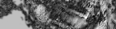
Create a new sketch, and select Add File from the Sketch menu. Find the lunar.jpg file from the media folder that you just unzipped and select it. If everything went well, the message area will read "1 file added to the sketch."
To check for the file, select Show Sketch Folder in the Sketch menu. You should see a folder named data, with a copy of lunar.jpg inside. When you add a file to the sketch, the data folder will automatically be created.Instead of using the Add File menu command, you can do the same thing by dragging files into the editor area of the Processing window. The files will be copied to the data folder the same way (and the data folder will be created if none exists).
You can also create the data folder outside of Processing and copy files there yourself. You won't get the message saying that files have been added, but this is a helpful method when you're working with large numbers of files.
Note
On Windows and Mac OS X, extensions are hidden by default. It's a good idea to change that option so that you always see the full name of your files. On Mac OS X, select Preferences from the Finder menu, and then make sure "Show all filename extensions" is checked in the Advanced tab. On Windows, look for "Folder Options," and set the option there.
There are three steps to follow before you can draw an image to the screen:
Add the image to the sketch's data folder (instructions given previously).
Create a PImage variable to store the image.
Load the image into the variable with loadImage().
After all three steps are done, you can draw the image to the screen with the image() function. The first parameter to image() specifies the image to draw; the second and third set the x- and y-coordinates:
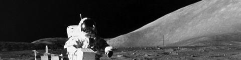
PImageimg;voidsetup(){size(480,120);img=loadImage("lunar.jpg");}voiddraw(){image(img,0,0);}
Optional fourth and fifth parameters set the width and height to draw the image. If the fourth and fifth parameters are not used, the image is drawn at the size at which it was created.
These next examples show how to work with more than one image in the same program and how to resize an image.
For this example, you'll need to add the capsule.jpg file (found in the media folder you downloaded) to your sketch using one of the methods described earlier.
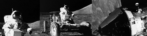
PImageimg1;PImageimg2;voidsetup(){size(480,120);img1=loadImage("lunar.jpg");img2=loadImage("capsule.jpg");}voiddraw(){image(img1,−120,0);image(img1,130,0,240,120);image(img2,300,0,240,120);}
When the mouseX and mouseY values are used as part of the fourth and fifth parameters of image(), the image size changes as the mouse moves:
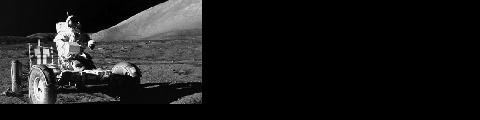
PImageimg;voidsetup(){size(480,120);img=loadImage("lunar.jpg");}voiddraw(){background(0);image(img,0,0,mouseX*2,mouseY*2);}
Note
When an image is displayed larger or smaller than its actual size, it may become distorted. Be careful to prepare your images at the sizes they will be used. When the display size of an image is changed with the image() function, the actual image on the hard drive doesn't change.
Processing can load and display raster images in the JPEG, PNG, and GIF formats. (Vector shapes in the SVG format can be displayed in a different way, as described in "Shapes," later in this chapter.) You can convert images to the JPEG, PNG, and GIF formats using programs like GIMP and Photoshop. Most digital cameras save JPEG images, but they usually need to be reduced in size before being used with Processing. A typical digital camera creates an image that is several times larger than the drawing area of most Processing sketches, so resizing such images before they are added to the data folder makes sketches run more efficiently, and can save disk space.
GIF and PNG images support transparency, which means that pixels can be invisible or partially visible (recall the discussion of color() and alpha values in Color–Example 3-17: Set Transparency). GIF images have 1-bit transparency, which means that pixels are either fully opaque or fully transparent. PNG images have 8-bit transparency, which means that each pixel can have a variable level of opacity. The following examples show the difference, using the clouds.gif and clouds.png files found in the media folder that you downloaded. Be sure to add them to the sketch before trying each example.
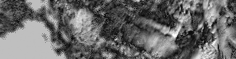
PImageimg;voidsetup(){size(480,120);img=loadImage("clouds.gif");}voiddraw(){background(255);image(img,0,0);image(img,0,mouseY*−1);}
PImageimg;voidsetup(){size(480,120);img=loadImage("clouds.png");}voiddraw(){background(204);image(img,0,0);image(img,0,mouseY*−1);}
Note
Remember to include the file extensions .gif, .jpg, or .png when you load the image. Also, be sure that the image name is typed exactly as it appears in the file, including the case of the letters. And if you missed it, read the note earlier in this chapter about making sure that the file extensions are visible on Mac OS X and Windows.
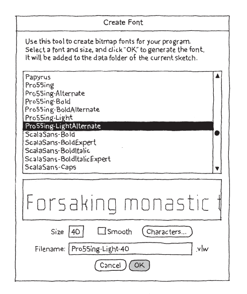
Processing can display text in many fonts other than the default. Before you display text in a different typeface, you need to convert one of the fonts on your computer to the VLW format, which stores each letter as a small image. To do this, select Create Font from the Tools menu to open the dialog box (Figure 6-1). Specify the font you want to convert, as well as the size and whether you want it to be smooth (anti-aliased).
Note
Make the font size selection carefully by considering the following: create the font at the size you want to use it in your sketch (or larger), but keep in mind that larger sizes increase the font file size. Select the Characters option only if you'll be using non-Roman characters like Japanese or Chinese text, because this also increases the file size significantly.
When you click the OK button in the Create Font tool, the VLW font is created and placed in the sketch's data folder. Now it's possible to load the font and add words to a sketch. This part is similar to working with images, but there's one extra step:
Add the font to the sketch's data folder (instructions given previously).
Create a PFont variable to store the font.
Load the font into the variable with loadFont().
Use the textFont() command to set the current font.
Now you can draw these letters to the screen with the text() function, and you can change the size with textSize(). For this example, you'll need to use the Create Font tool to create a VLW font (and modify the loadFont() line to use it), or you can use AndaleMono-36.vlw from the media folder:
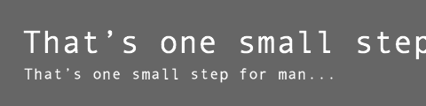
PFontfont;voidsetup(){size(480,120);smooth();font=loadFont("AndaleMono-36.vlw");textFont(font);}voiddraw(){background(102);textSize(36);text("That's one small step for man...",25,60);textSize(18);text("That's one small step for man...",27,90);}
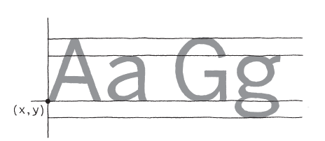
The first parameter to text() is the character(s) to draw to the screen. (Notice that the characters are enclosed within quotes.) The second and third parameters set the horizontal and vertical location. The location is relative to the baseline of the text (see Figure 6-2).
You can also set text to draw inside a box by adding fourth and fifth parameters that specify the width and height of the box:

PFontfont;voidsetup(){size(480,120);font=loadFont("AndaleMono-24.vlw");textFont(font);}voiddraw(){background(102);text("That's one small step for man...",26,30,240,100);}
In the previous example, the words inside the text() function start to make the code difficult to read. We can store these words in a variable to make the code more modular. The String data type is used to store text data. Here's a new version of the previous example that uses a String:
PFontfont;Stringquote="That's one small step for man...";voidsetup(){size(480,120);font=loadFont("AndaleMono-24.vlw");textFont(font);}voiddraw(){background(102);text(quote,26,30,240,100);}
There's a set of additional functions that affect how letters are displayed on screen. They are explained, with examples, in the Typography category of the Processing Reference.
If you make vector shapes in a program like Inkscape or Illustrator, you can load them into Processing directly. This is helpful for shapes you'd rather not build with Processing's drawing functions. As with images, you need to add them to your sketch before they can be loaded.
There are three steps to load and draw an SVG file:
Add an SVG file to the sketch's data folder.
Create a PShape variable to store the vector file.
Load the vector file into the variable with loadShape().
After following these steps, you can draw the image to the screen with the shape() function:
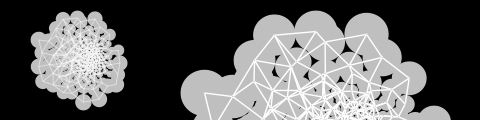
PShapenetwork;voidsetup(){size(480,120);smooth();network=loadShape("network.svg");}voiddraw(){background(0);shape(network,30,10);shape(network,180,10,280,280);}
The parameters for shape() are similar to image(). The first parameter tells shape() which SVG to draw and the next pair sets the position. Optional fourth and fifth parameters set the width and height.
Unlike raster images, vector shapes can be scaled to any size without losing resolution. In this example, the shape is scaled based on the mouseX variable, and the shapeMode() function is used to draw the shape from its center, rather than the default position, the upper-left corner:
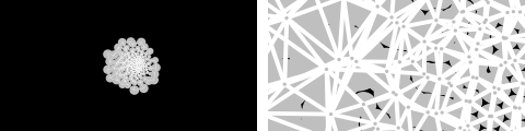
PShapenetwork;voidsetup(){size(240,120);smooth();shapeMode(CENTER);network=loadShape("network.svg");}voiddraw(){background(0);floatdiameter=map(mouseX,0,width,10,800);shape(network,120,60,diameter,diameter);}
Note
There are limitations to the type of SVG file that you can load. Processing doesn't support all SVG features. See the Processing Reference for PShape for more details.
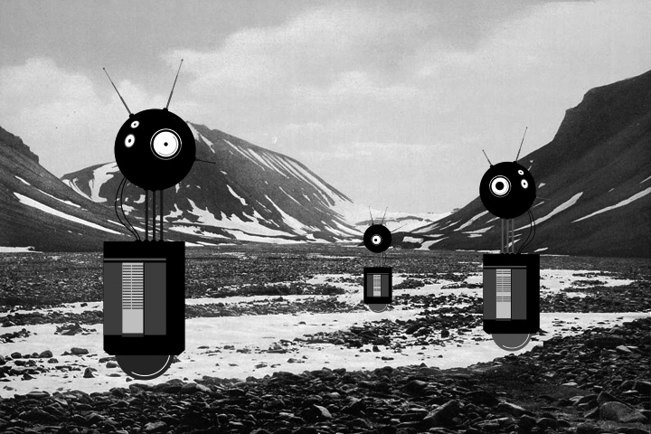
Unlike the robots created from lines and rectangles drawn in Processing in the previous chapters, these robots were created with a vector drawing program. For some shapes, it's often easier to point and click in a software tool like Inkscape or Illustrator than to define the shapes with coordinates in code.
There's a trade-off to selecting one image creation technique over another. When shapes are defined in Processing, there's more flexibility to modify them while the program is running. If the shapes are defined elsewhere and then loaded into Processing, changes are limited to the position, angle, and size. When loading each robot from an SVG file, as this example shows, the variations featured in Robot 2 (see Robot 2: Variables in Chapter 4) are impossible.
Images can be loaded into a program to bring in visuals created in other programs or captured with a camera. With this image in the background, our robots are now exploring for life forms in Norway at the dawn of the 20th century.
The SVG and PNG file used in this example can be downloaded from http://www.processing.org/learning/books/media.zip.
PShapebot1;PShapebot2;PShapebot3;PImagelandscape;floateasing=0.05;floatoffset=0;voidsetup(){size(720,480);bot1=loadShape("robot1.svg");bot2=loadShape("robot2.svg");bot3=loadShape("robot3.svg");landscape=loadImage("alpine.png");smooth();}voiddraw(){// Set the background to the "landscape" image; this image// must be the same width and height as the programbackground(landscape);// Set the left/right offset and apply easing to make// the transition smoothfloattargetOffset=map(mouseY,0,height,−40,40);offset+=(targetOffset-offset)*easing;// Draw the left robotshape(bot1,85+offset,65);// Draw the right robot smaller and give it a smaller offsetfloatsmallerOffset=offset*0.7;shape(bot2,510+smallerOffset,140,78,248);// Draw the smallest robot, give it a smaller offsetsmallerOffset*=−0.5;shape(bot3,410+smallerOffset,225,39,124);}