
![]()
Arduino-Based Sensor Nodes
One of the greatest advances in physical computing has been the proliferation of microcontrollers. A microcontroller consists of a processor with a small instruction set,1 memory, and programmable input/output circuitry contained on a single chip. Microcontrollers are usually packaged with supporting circuitry and connections on a small printed circuit board.
Microcontrollers are used in embedded systems where small software programs can be tailored to control and monitor hardware devices, making them ideal for use in sensor networks. One of the most successful and most popular microcontrollers is the Arduino platform.
In this chapter, you explore the Arduino platform with the goal of using the Arduino to manage sensor nodes. You see a short tutorial on the Arduino and several projects to help get you started working with the Arduino.
What Is an Arduino?
The Arduino is an open source hardware prototyping platform supported by an open source software environment. It was first introduced in 2005 and was designed with the goal of making the hardware and software easy to use and available to the widest audience possible. Thus, you do not have to be an electronics expert to use the Arduino.
The original target audience included artists and hobbyists who needed a microcontroller to make their designs and creations more interesting. However, given its ease of use and versatility, the Arduino has quickly become the choice for a wider audience and a wider variety of projects.
This means you can use the Arduino for all manner of projects from reacting to environmental conditions to controlling complex robotic functions. The Arduino has also made learning electronics easier through practical applications.
Another aspect that has helped the rapid adoption of the Arduino platform is the growing community of contributors to a wealth of information made available through the official Arduino web site (http://arduino.cc/en/). When you visit the web site, you find an excellent “getting started” tutorial as well as a list of helpful project ideas and a full reference guide to the C-like language for writing the code to control the Arduino (called a sketch).
Arduino also provides an integrated development environment called the Arduino IDE. The IDE runs on your computer (called the host), where you can write and compile sketches and then upload them to the Arduino via USB connections. The IDE is available for Linux, Mac, and Windows. It is designed around a text editor especially designed for writing code and a set of limited functions designed to support compilation and loading of sketches.
Sketches are written in a special format consisting of only two required methods—one that executes when the Arduino is reset or powered on and another that executes continuously. Thus, your initialization code goes in setup() and your code to control the Arduino goes in loop(). The language is C-like, and you may define your own variables and functions. For a complete guide to writing sketches, see http://arduino.cc/en/Tutorial/Sketch.
You can expand the functionality of sketches and provide for reuse by writing libraries that encapsulate certain features such as networking, using memory cards, connecting to databases, doing mathematics, and the like. Many such libraries are included with the IDE. There are also some libraries written by others and contributed to Arduino.cc through open source agreements—some of which have been bundled with the IDE.
The Arduino supports a number of analog and digital pins that you can use to connect to various devices and components and interact with them. The mainstream boards have specific pin layouts, or headers, that allow the use of expansion boards called shields. Shields let you add additional hardware capabilities such as Ethernet, Bluetooth, and XBee support to your Arduino. The physical layout of the Arduino and the shield allow you to stack shields. Thus, you can have an Ethernet shield as well as an XBee shield, because each uses different I/O pins. You learn the use of the pins and shields as you explore the application of Arduino to sensor networks.
The next sections examine the various Arduino boards and briefly describe their capabilities. I list the boards by when they became available, starting with the most recent models. Many more boards and variants are available, and a few new ones are likely to be out by the time this book is printed, but these are the ones that are typically used in a sensor network project.
A growing number of Arduino boards are available. Some are configured for special applications, whereas others are designed with different processors and memory configurations. Some boards are considered official Arduino boards because they are branded and endorsed by Arduino.cc. Because the Arduino is open source and, more specifically, licensed using a Creative Commons Attribution Share-Alike license, anyone can build Arduino-compatible boards (often called Arduino clones). However, you must follow the rules and guidelines set forth by Arduino.cc.2 This section examines some of the more popular Arduino branded boards.
The basic layout of an Arduino board consists of a USB connection, a power connector, a reset switch, LEDs for power and serial communication, and a standard spaced set of headers for attaching shields. The official boards sport a distinctive blue-colored PCB with white lettering. With the exception of one model, all the official boards can be mounted in a chassis (they have holes in the PCB for mounting screws). The exception is an Arduino designed for mounting on a breadboard.
The Leonardo board represents a bold leap forward for the Arduino platform. Although it supports the standard header layout, ensuring the continued use of shields, it also includes a USB controller that allows the board to appear as a USB device to the host computer. The board uses a newer ATmega32u4 processor with 20 digital I/O pins, of which 12 can be used as analog pins and 7 can be used as a pulse-width modulation (PWM) output. It has 32KB of flash memory and 2.5KB of SRAM.
The Leonardo has more digital pins than its predecessor but continues to support most shields. The USB connection uses a smaller USB connector. The board is also available with and without headers. Figure 3-1 depicts an official Leonardo board. Details and a full datasheet can be found at http://arduino.cc/en/Main/ArduinoBoardLeonardo.
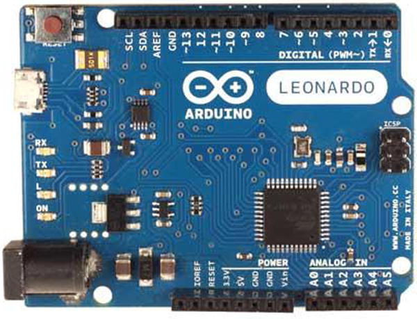
Figure 3-1. Arduino Leonardo (courtesy of Arduino.cc)
The Uno board is the first standard Arduino board featuring an ATmega328 processor; 14 digital I/O pins, of which 6 can be used as PWM output; and 6 analog input pins. The Uno board has 32KB of flash memory and 2KB of SRAM.
The Uno is available either as a surface-mount device (SMD) or a standard IC socket. The IC socket version allows you to exchange processors, should you desire to use an external IC programmer to build custom solutions. Details and a full datasheet are available at http://arduino.cc/en/Main/ArduinoBoardUno. It has a standard USB type B connector and supports all shields. Figure 3-2 depicts the Arduino Uno revision 3 board.

Figure 3-2. Arduino Uno (courtesy of Arduino.cc)
The Arduino Due is a new, larger, and faster board based on the Atmel SAM3X8E ARM Cortex-M3 processor. The processor is a 32-bit processor, and the board supports a massive 54 digital I/O ports, of which 14 can be used for PWM output; 12 analog inputs; and 4 UART chips (serial ports); as well as 2 digital-to-analog (DAC) and 2 two-wire interface (TWI) pins. The new processor offers several advantages:
- 32-bit registers
- DMA controller (allows CPU-independent memory tasks)
- 512KB flash memory
- 96KB SRAM
- 84MHz clock
The Due has the larger form factor (called the mega footprint)3 but still supports the use of standard shields as well as mega format shields. The new board has one distinct limitation: unlike other boards that can accept up to 5V on the I/O pins, the Due is limited to 3.3V on the I/O pins.
The Arduino Due is intended to be used for projects that require more processing power, more memory, and more I/O pins. Despite the significant capabilities of the new board it remains open source and comparable in price to its predecessors. Look to the Due for your projects that require the maximum hardware performance. Figure 3-3 shows an Arduino Due board.

Figure 3-3. Arduino Due (courtesy of Arduino.cc)
Mega 2560
The Arduino Mega 2560 is an older form of the Due. It is based on the ATmega2560 processor (hence the name). Like the Due, the board supports a massive 54 digital I/O ports, of which 14 can be used as PWM output; 16 analog inputs; and 4 UARTs (hardware serial ports). It uses a 16MHz clock and has 256KB of flash memory.
The Mega 2560 is essentially a larger form of the standard Arduino (Uno, Duemilanove, etc.) and supports the standard shields. Figure 3-4 shows the Arduino Mega 2560 board.
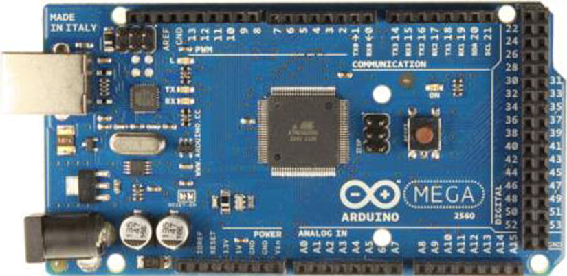
Figure 3-4. Arduino Mega (courtesy of Arduino.cc)
Interestingly, the Arduino Mega 256 is the board of choice for Prusa Mendel and similar 3D printers that require the use of a controller board named RepRap Arduino Mega Pololu Shield (RAMPS).
Mini
The Arduino Mini is a small form-factor board designed for use with breadboards. Thus, it has all its pins arranged in male headers that plug directly into a standard breadboard. It is based on the ATmega328 processor (older models use the ATmega168) and has 14 digital I/O pins, of which 6 can be used as PWM output, and 8 analog inputs. The Mini has 32KB of flash memory and uses a 16MHz clock.
Unlike other Arduino boards, the Mini does not have a USB connector. To connect to and program the Mini, you must use a USB Serial adapter or RS232-to-TTL serial adapter. Figure 3-5 shows the Arduino Mini.

Figure 3-5. Arduino Mini (courtesy of Arduino.cc)
![]() Note The Mini has a limitation with regard to input voltage. You should avoid voltages over 9V.
Note The Mini has a limitation with regard to input voltage. You should avoid voltages over 9V.
Micro
The Arduino Micro is a special form of the new Leonardo board and uses the same ATmega32u4 processor with 20 digital I/O pins, of which 12 can be used as analog pins and 7 can be used as PWM output. It has 32KB of flash memory and 2.5KB of SRAM.
The Micro was made for use on breadboards in the same way as the Mini but in a newer, updated form. But unlike the Mini, the Micro is a full-featured board complete with USB connector. And like the Leonardo, it has built-in USB communication, allowing the board to connect to a computer as a mouse or keyboard. Figure 3-6 shows the Arduino Micro board.
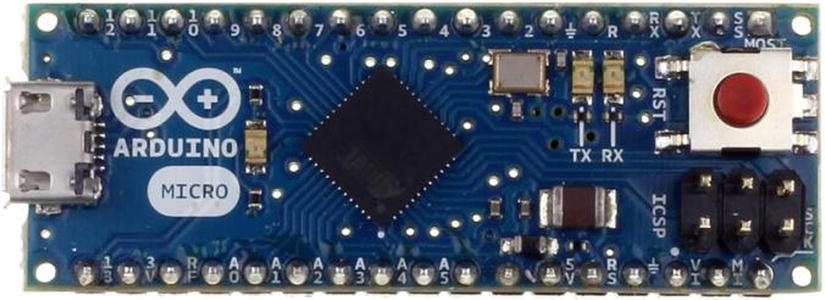
Figure 3-6. Arduino Micro (courtesy of Arduino.cc)
Although branded as an official Arduino board, the Arduino Micro is produced in cooperation with Adafruit.
Nano
The Arduino Nano is an older form of the Arduino Micro. In this case, it is based on the functionality of the Duemilanove4 and has the ATmega328 processor (older models use the ATmega168) and 14 digital I/O pins, of which 6 can be used as PWM output, and 8 analog inputs. The mini has 32KB of flash memory and uses a 16MHz clock.
Like the Micro, it has all the features needed for connecting to and programming via a USB connection. Figure 3-7 shows an Arduino Nano board.

Figure 3-7. Arduino Nano (courtesy of Arduino.cc)
A growing number of Arduino boards are available from a large number of sources. Because the Arduino is open hardware, it is not unusual or the least bit illicit to find Arduino boards made by vendors all over the world.
Although some would insist the only real Arduinos are those branded as such, the truth of the matter is that as long as the build quality is sound and the components are of high quality, the choice of using a branded versus a copy, hence clone, is one of personal preference. I have sampled Arduino boards from a number of sources, and with few exceptions they all perform their intended functions superbly.
Except for the Arduino Mini, the Arduino clone boards have a greater variety of hardware configurations. Some Arduinos are designed for use in embedded systems or on breadboards, and some are designed for prototyping. I examine a number of the more popular clone boards in the following sections.
The Arduino Pro is manufactured by SparkFun (www.sparkfun.com/). It is based on the ATmega328 processor (older models use the ATmega168) and has 14 digital I/O pins, of which 6 can be used as PWM output, and 8 analog inputs. The Pro has 32KB of flash memory and 2KB of SRAM, and it uses a 16MHz clock.
The Arduino Pro has a footprint similar to the Uno but does not come with headers. However, it can support standard shields if headers are added. This makes the Arduino Pro ideal for use in semi-permanent installations where the pins can be soldered to the components or circuitry. Figure 3-8 shows an Arduino Pro board.

Figure 3-8. Arduino Pro (courtesy of Arduino.cc)
Also, the Pro does not include a USB connector and therefore must be connected to and programmed with an FTDI cable or similar breakout board. It comes as either a 3.3V model with an 8MHz clock or a 5V model with a 16MHz clock. Because it is intended for permanent installation, it also provides a connector for battery power.
The Arduino Pro Mini is another board from SparkFun. It is based on the ATmega168 processor (older models use the ATmega168) and has 14 digital I/O pins, of which 6 can be used as PWM output, and 8 analog inputs. The Pro Mini has 16KB of flash memory and 1KB of SRAM, and it uses a 16MHz clock.
The Arduino Pro Mini is modeled on the Arduino Mini and is also intended for use on breadboards but does not come with headers. This makes the Arduino Pro Mini ideal for use in semi-permanent installations where the pins can be soldered to the components or circuitry and space is a premium. Figure 3-9 shows an Arduino Pro Mini board.

Figure 3-9. Arduino Pro Mini (courtesy of Arduino.cc)
Also, the Pro Mini does not include a USB connector and therefore must be connected to and programmed with a FTDI cable or similar breakout board. It comes as either a 3.3V model with a 8MHz clock or a 5V model with a 16MHz clock.
Fio
The Arduino Fio is yet another board made by SparkFun. It was designed for use in wireless projects. It is based on the ATmega328P processor with 14 digital I/O pins, of which 6 can be used as PWM outputs, and 8 analog pins. It has 32KB of flash memory and 2KB of SRAM.
The Fio requires a 3.3V power supply, which allows for use with a lithium polymer (LiPo) battery which can be recharged via the USB connector on the board.
Its wireless pedigree can be seen in the XBee socket on the bottom of the board. Although the USB connection lets you recharge the battery, you must use an FTDI cable or breakout adapter to connect to and program the Fio. Similar to the Pro models, the Fio does not come with headers, allowing the board to be used in semi-permanent installations where connections are soldered in place. Figure 3-10 shows an Arduino Fio board.

Figure 3-10. Arduino Fio (courtesy of Arduino.cc)
The Seeeduino is an Arduino clone made by Seeed Studio (www.seeedstudio.com). It is based on the ATmega328P processor and has 14 digital I/O pins, of which 6 can be used as PWM outputs, and 8 analog pins. It has 32KB of flash memory and 2KB of SRAM.
The board has a footprint similar to the Arduino Uno and supports all standard headers. It supports a number of enhancements such as I2C and serial Grove connectors and a mini USB connector, and it uses SMD components. It is also a striking red color with yellow headers. Figure 3-11 shows a Seeeduino board.

Figure 3-11. Seeeduino (courtesy of Seeed Studio)
Sippino
The Sippino from SpikenzieLabs (www.spikenzielabs.com) is designed to be used on a solder-less breadboard. It costs less because it has fewer components and a much smaller footprint. Fortunately, SpikenzieLabs also provides a special adapter called a shield dock that allows you to use a Sippino with standard Arduino shields.
It is based on the ATmega328 processor and has 14 digital I/O pins, of which 6 can be used as PWM output, and 6 analog input pins. The Sippino board has 32KB of flash memory and 2KB of SRAM.
The Sippino does not have a USB connection, so you have to use an FTDI cable to program it. The good news is you need only one cable no matter how many Sippinos you have in your project. I have a number of Sippinos and use them in many of my Arduino projects where space is at a premium. Figure 3-12 shows a Sippino mounted on a breadboard.

Figure 3-12. Sippino (courtesy of SpikenzieLabs)
The shield dock is an amazing add-on that lets you use the Sippino as if it were a standard Uno or Duemilanove. Figure 3-13 shows a Sippino mounted on a shield dock.
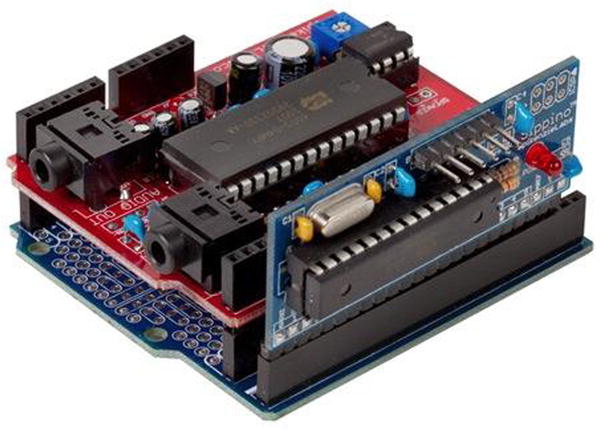
Figure 3-13. Sippino on a shield dock (courtesy of SpikenzieLabs)
Prototino
The Prototino is another product of SpikenzieLabs. It has the same components as the Sippino, but instead of a breadboard-friendly layout, it is mounted on a PCB that includes a full prototyping area. Like the Sippino, it is based on the ATmega328 processor and has 14 digital I/O pins, of which 6 can be used as PWM output, and 6 analog input pins. The Prototino board has 32KB of flash memory and 2KB of SRAM.
The Prototino is ideal for building solutions that have supporting components and circuitry. In some ways it is similar to the Nano, Mini, and similar boards in that you can use it for permanent installations. But unlike those boards (and even the Arduino Pro), the Prototino provides a space for you to add your components directly to the board. I have used a number of Prototino boards for projects where I have added the components to the Prototino and install it in the chassis. This allowed me to create a solution using a single board and even build several copies quickly and easily.
Like the Sippino, the Prototino does not have a USB connection, so you have to use an FTDI cable to program it. Figure 3-14 shows a Prototino board.

Figure 3-14. Prototino (courtesy of SpikenzieLabs)
THERE IS EVEN ONE MADE OF PAPER
Every now and then you encounter something mundane that’s made truly interesting by a change in medium. Such is the case of the PAPERduino created by Guilherme Martins. The PAPERduino is a minimal Arduino that uses a paper template in place of the PCB. All you need to do is download and print out the templates, purchase a small list of commonly available discrete components, and follow the connection diagram printed on the template to solder the components to short lengths of wire. You can find out more by visiting the following web site: http://lab.guilhermemartins.net/2009/05/06/paperduino-prints/.
So, Which Do I Buy?
If you’re wondering which Arduino to buy, the answer depends on what you want to do. For most of the projects in this book, any Arduino Uno or similar clone that supports the standard shield headers is fine. You need not buy the larger Due or its predecessors, since the added memory and I/O pins aren’t needed.
I use the Arduino Uno as the basis for all the projects in this book. Although you can use an older board without issues, there are some issues with using the newer Leonardo board. I point these out as you encounter them. Most issues have to do with the relocated pins on the Leonardo board. For example, the SPI header pins (at upper left in Figure 3-2) have been moved on the Leonardo.
If you want to save some money, you can build all the Arduino projects in this book with the older Arduino Duemilanove board. If you look around, you may find these boards at bargain prices. There are also a lot of Duemilanove clones. In fact, a quick search on eBay shows about a dozen examples for around $15.00 USD as compared to $30.00 or more for an Uno or a Leonardo.
For future projects, there are some things you should consider before choosing the Arduino. For example, if your project is largely based on a breadboard or you want to keep the physical size of the project to a minimum, and you aren’t going to use any shields, the Arduino Mini may be the better choice. Conversely, if you plan to do a lot of programming to implement complex algorithms for manipulating or analyzing data, you may want to consider the Due for its added processing power and memory.
The bottom line is that most of the time your choice will be based on physical characteristics (size, shield support, and so on) and seldom on processing power or memory. SparkFun has an excellent buyer’s guide in which you can see the pros and cons of each choice. See www.sparkfun.com/pages/arduino_guide for more details.
Where to Buy
Due to the popularity of the Arduino platform, many vendors sell Arduino and Arduino clone boards, shields, and accessories. The Arduino.cc web site (http://arduino.cc/en/Main/Buy) also has a page devoted to approved distributors. If none of the resources listed here are available to you, you may want to check this page for a retailer near you.
There are a growing number of online retailers where you can buy Arduino boards and accessories. The following lists a few of the more popular sites.
- SparkFun: From discrete components to the company’s own branded Arduino clones and shields, SparkFun has just about anything you could possibly want for the Arduino platform. www.sparkfun.com/
- Adafruit: Carries a growing array of components, gadgets, and more. It has a growing number of products for the electronics hobbyist, including a full line of Arduino products. Adafruit also has an outstanding documentation library and wiki to support all the products it sells. www.adafruit.com/
- Maker Shed: The front store for MAKE Magazine and the Maker movement, Maker Shed has many products for the Arduino platform, including a growing number of custom project kits. From building your own bass guitar to building a robot, this store will tell you it has a lot to offer. www.makershed.com
You can also visit the manufacturers of some of the clone boards. The following are the leading clone manufacturers and links to their storefronts:
- SpikenzieLabs: www.spikenzielabs.com/
- Seeed Studio: www.seeedstudio.com/
There are also brick-and-mortar stores that carry Arduino products. Although there aren’t as many as there are online retailers, and their inventories are typically limited, if you need a new Arduino board quickly you can find them at the following retailers. You may find additional retailers in your area. Look for popular hobby electronic stores:
- Radio Shack: Most stores are independently owned, but most carry a modest array of Arduino boards, shields, and accessories, including Arduino-branded products as well as popular clone products. www.radioshack.com/
- Fry’s: An electronics superstore with a huge inventory of electronics, components, microcontrollers, computer parts, and more. If you have never had the chance to visit a Fry’s store, you should be prepared to spend some time there. Fry’s carries Arduino-branded boards, shields, and accessories as well as products from Parallax, SparkFun, and many more. http://frys.com/
- Micro Center: Micro Center is similar to Fry’s, offering a huge inventory of products. However, most Micro Center stores have a smaller inventory of electronic components than Fry’s. www.microcenter.com/
Now that you have a better understanding of the hardware details and the variety of Arduino boards available, let’s dive in to how to use and program the Arduino. The next section provides a tutorial for installing the Arduino programming environment and programming the Arduino. Later sections present projects to build your skills for developing sensor networks.
This section is a short tutorial on getting started using an Arduino. It covers obtaining and installing the IDE and writing a sample sketch. Rather than duplicate the excellent works that precede this book, I cover the highlights and refer readers who are less familiar with the Arduino to online resources and other books that offer a much deeper introduction. Also, the Arduino IDE has many sample sketches that you can use to explore the Arduino on your own. Most have corresponding tutorials on the Arduino.cc site.
A lot of information is available about the Arduino platform. If you are just getting started with the Arduino, Apress offers an impressive array of books covering all manner of topics concerning the Arduino, ranging from getting started using the microcontroller to learning the details of its design and implementation. The following is a list of the more popular books:
- Beginning Arduino by Michael McRoberts (Apress, 2010)
- Practical Arduino: Cool Projects for Open Source Hardware (Technology in Action) by Jonathan Oxer and Hugh Blemings (Apress, 2009)
- Arduino Internals by Dale Wheat (Apress, 2011)
There are also some excellent online resources for learning more about the Arduino, the Arduino libraries, and sample projects. The following are some of the best:
- Arduino.cc: http://arduino.cc/en/
- Adafruit tutorials: http://learn.adafruit.com/
- Make tutorials: http://makezine.com/category/electronics/arduino/
The Arduino IDE
The Arduino IDE is available for download for the Mac, Linux (32- and 64-bit versions), and Windows platforms. You can download the IDE from http://arduino.cc/en/Main/Software. There are links for each platform as well as a link to the source code if you need to compile the IDE for a different platform.
Installing the IDE is straightforward. I omit the actual steps of installing the IDE for brevity, but if you require a walkthrough of installing the IDE you can see the Getting Started link on the download page or read more in Beginning Arduino by Michael McRoberts (Apress, 2010).
Once the IDE launches, you see a simple interface with a text editor area (a white background by default), a message area beneath the editor (a black background by default), and a simple button bar at the top. The buttons are (from left to right) Compile, Compile and Upload, New, Open, and Save. There is also a button to the right that opens the serial monitor. You use the serial monitor to view messages from the Arduino sent (or printed) via the Serial library. You see this in action in your first project. Figure 3-15 shows the Arduino IDE
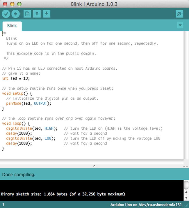
Figure 3-15. The Arduino IDE
Notice that in Figure 3-15 you see a sample sketch (called blink) and the result of a successful compile operation. Notice also at the bottom that it tells you that you are programming an Arduino Uno board on a specific serial port.
Due to the differences in processor and supporting architecture, there are some differences in how the compiler builds the program (and how the IDE uploads it). Thus, one of the first things you should do when you start the IDE is choose your board from the Tools ![]() Board menu. Figure 3-16 shows a sample of selecting the board on the Mac.
Board menu. Figure 3-16 shows a sample of selecting the board on the Mac.

Figure 3-16. Choosing the Arduino board
Notice the number of boards available. Be sure to choose the one that matches your board. If you are using a clone board, check the manufacturer’s site for the recommended setting to use. If you choose the wrong board, you typically get an error during upload, but it may not be obvious that you’ve chosen the wrong board. Because I have so many different boards, I’ve made it a habit to choose the board each time I launch the IDE.
The next thing you need to do is choose the serial port to which the Arduino board is connected. To connect to the board, use the Tools ![]() Serial Port menu option. Figure 3-17 shows an example on the Mac. In this case, no serial ports are listed. This can happen if you haven’t plugged your Arduino in to the computer’s USB ports (or hub), you had it plugged in but disconnected it at some point, or you have not loaded the drivers for the Arduino (Windows). Typically, this can be remedied by simply unplugging the Arduino and plugging it back in and waiting until the computer recognizes the port.
Serial Port menu option. Figure 3-17 shows an example on the Mac. In this case, no serial ports are listed. This can happen if you haven’t plugged your Arduino in to the computer’s USB ports (or hub), you had it plugged in but disconnected it at some point, or you have not loaded the drivers for the Arduino (Windows). Typically, this can be remedied by simply unplugging the Arduino and plugging it back in and waiting until the computer recognizes the port.
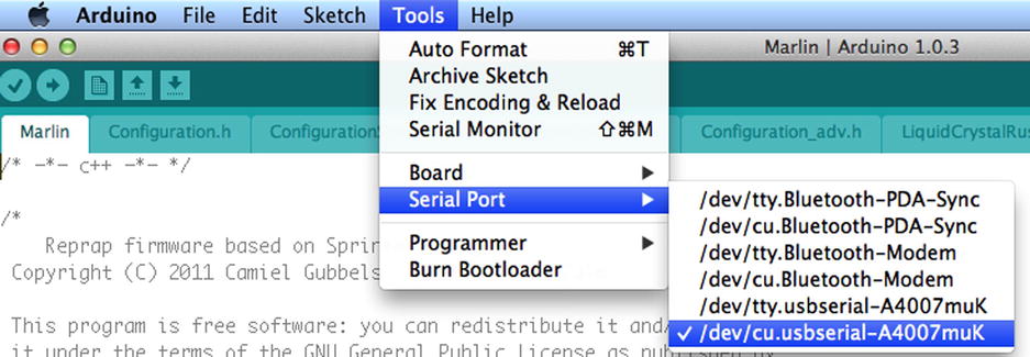
Figure 3-17. Choosing the serial port
![]() Note If you use a Mac, it doesn’t matter which port you choose: either the one that starts with tty or the one that starts with cu will work.
Note If you use a Mac, it doesn’t matter which port you choose: either the one that starts with tty or the one that starts with cu will work.
![]() Tip See http://arduino.cc/en/Guide/Howto if you need help installing the drivers on Windows.
Tip See http://arduino.cc/en/Guide/Howto if you need help installing the drivers on Windows.
OK, now that you have your Arduino IDE installed, you can connect your Arduino and set the board and serial port. You see the LEDs on the Arduino illuminate. This is because the Arduino is getting power from the USB. Thus, you do not need to provide an external power supply when the Arduino is connected to your computer. Next, you dive into a simple project to demonstrate the Arduino IDE and learn how basic sketches are built, compiled, and uploaded.
Project: Hardware “Hello, World!”
The ubiquitous “Hello, World!” project for the Arduino is the blinking light. The project uses an LED, a breadboard, and some jumper wires. The Arduino turns on and off through the course of the loop() iteration. That’s a fine project for getting started, but it does not relate to how sensors could be used.
Thus, in this section, you expand on the blinking light project by adding a sensor. In this case, you still keep things simple by using what is arguably the most basic of sensors: a pushbutton. The goal is to illuminate the LED whenever the button is pushed.
Let’s begin by assembling an Arduino. Be sure to disconnect (power down) the Arduino first. You can use any Arduino variant that has I/O pins. Place one LED and one pushbutton in the breadboard. Wire the 5V pin to the breadboard power rail and the ground pin to the ground rail, and place the pushbutton in the center of the breadboard. Place the LED to one side of the breadboard, as shown in Figure 3-18.

Figure 3-18. Diagram of an LED with a pushbutton
You’re almost there. Now wire a jumper from the power rail to one side of the pushbutton, and wire the other side of the pushbutton to (DIGITAL) pin 2 on the Arduino (located on the side with the USB connector). Next, wire the LED to ground on the breadboard and a 150-Ohm resistor (colors: brown, green, brown, gold). The other side of the resistor should be wired to pin 13 on the Arduino. You also need a resistor to pull the button low when the button is not pressed. Place a 10K Ohm resistor (colors: brown, black, orange, gold) on the side of the button with the wire to pin 2 and ground.
The longest side of the LED is the positive side. The positive side should be the one connected to the resistor. It doesn’t matter which direction you connect the resistor; it is used to limit the current to the LED. Check the drawing again to ensure that you have a similar setup.
![]() Tip If you power on your shiny new Arduino, you may see the LED on the board flash. This is because some Arduino boards come with the blink sketch preloaded.
Tip If you power on your shiny new Arduino, you may see the LED on the board flash. This is because some Arduino boards come with the blink sketch preloaded.
![]() Note Most Arduino boards have an LED connected to pin 13. You reuse the pin to demonstrate how to use analog output. Thus, you may see a small LED near pin 13 illuminate at the same time as the LED on the breadboard.
Note Most Arduino boards have an LED connected to pin 13. You reuse the pin to demonstrate how to use analog output. Thus, you may see a small LED near pin 13 illuminate at the same time as the LED on the breadboard.
COOL GADGET
One of the coolest gadgets for working with the Arduino is the Arduino mounting plate from Adafruit (www.adafruit.com/products/275).
This small acrylic plate has space for a half-sized breadboard and an Arduino. It even has mounting holes for bolting the Arduino to the plate and small rubber feet to keep the plate off the work surface. The following illustration (courtesy of Adafruit) shows the mounting plate in action.
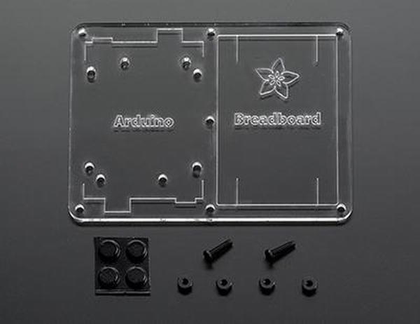
Although you can make your own Arduino mounting plate from Lexan or Plexiglas (I have), the Adafruit product is just a notch better than what you can make yourself. For about $5.00 USD, you can keep your Arduino and breadboard together and avoid scratches on your table (from the sharp prongs on the bottom of the Arduino)—and, better still, avoid the nasty side effects of accidentally placing a powered Arduino on a conductive surface (never a good idea).
Writing the Sketch
The sketch you need for this project uses two I/O pins on the Arduino: one output and one input. The output pin will be used to illuminate the LED, and the input pin will detect the pushbutton engagement. You connect positive voltage to one side of the pushbutton and the other side to the input pin. When you detect voltage on the input pin, you tell the Arduino processor to send positive voltage to the output pin. In this case, the positive side of the LED is connected to the output pin.
As you see in the drawing in Figure 3-18, the input pin is pin 2 and the output pin is pin 13. Let’s use a variable to store these numbers so you do not have to worry about repeating the hard-coded numbers (and risk getting them wrong). Use the pinMode() method to set the mode of each pin (INPUT, OUTPUT). You place the variable statements before the setup() method and set the pinMode() calls in the setup() method, as follows:
int led = 13;     // LED on pin 13
int button = 2;   // button on pin 2

void setup() {
  pinMode(led, OUTPUT);
  pinMode(button, INPUT);
}
In the loop() method, you place code to detect the button press. Use the digitalRead() method to read the status of the pin (LOW or HIGH), where LOW means there is no voltage on the pin and HIGH means positive voltage is detected on the pin.
You also place in the loop() method the code to turn on the LED when the input pin state is HIGH. In this case, you use the digitalWrite() method to set the output pin to HIGH when the input pin state is HIGH and similarly set the output pin to LOW when the input pin state is LOW. The following shows the statements needed:
void loop() {
  int state = digitalRead(button);
  if (state == HIGH) {
    digitalWrite(led, HIGH);
  }
  else {
    digitalWrite(led, LOW);
  }
}
Now let’s see the entire sketch, complete with proper documentation. Listing 3-1 shows the completed sketch.
Listing 3-1. Simple Sensor Sketch
/*
  Simple Sensor - Beginning Sensor Networks

  For this sketch, we explore a simple sensor (a pushbutton) and a simple
  response to sensor input (a LED). When the sensor is activated (the
  button is pushed), the LED is illuminated.
*/

int led = 13;     // LED on pin 13
int button = 2;   // button on pin 2

// the setup routine runs once when you press reset:
void setup() {
  // initialize pin 13 as an output.
  pinMode(led, OUTPUT);
  pinMode(button, INPUT);
}

// the loop routine runs over and over again forever:
void loop() {
  // read the state of the sensor
  int state = digitalRead(button);

  // if sensor engaged (button is pressed), turn on LED
  if (state == HIGH) {
    digitalWrite(led, HIGH);
  }
  // else turn off LED
  else {
    digitalWrite(led, LOW);
  }
}
When you’ve entered the sketch as written, you are ready to compile and run it.
![]() Tip Want to avoid typing all this by hand? You can find the source code on the Apress site for this book. See http://apress.com/9781430258247.
Tip Want to avoid typing all this by hand? You can find the source code on the Apress site for this book. See http://apress.com/9781430258247.
Once you have the sketch written, test the compilation using the Compile button in the upper-left corner of the IDE. Fix any compilation errors that appear in the message window. Typical errors include misspellings or case changes (the compiler is case sensitive) for variables or methods.
After you have fixed any compilation errors, click the Upload button. The IDE compiles the sketch and uploads the compiled sketch to the Arduino board. You can track the progress via the progress bar at lower right, above the message window. When the compiled sketch is uploaded, the progress bar disappears.
Once the upload is complete, what do you see on your Arduino? If you’ve done everything right, the answer is nothing. It’s just staring back at you with that one dark LED—almost mockingly. Now, press the pushbutton. Did the LED illuminate? If so, congratulations: you’re an Arduino programmer!
If the LED did not illuminate, hold the button down for a second or two. If that does not work, check all of your connections to make sure you are plugged in to the correct runs on the breadboard and that your LED is properly seated with the longer leg connected to the resistor, which is connected to pin 13.
On the other hand, if the LED stays illuminated, try reorienting your pushbutton 90 degrees. You may have set the pushbutton in the wrong orientation.
Try out the project a few times until the elation passes. If you’re an old hand at Arduino, that may be a very short period. If this is all new to you, go ahead and push that button and bask in the glory of having built your first sensor node!
The next section examines a more complicated sensor node, using a temperature and humidity sensor that sends digital data. As you will see, there is a lot more to do.
The digital and analog pins of the Arduino make it an ideal platform for hosting sensors. Since most sensors need very little in the way of supporting components, you can often host multiple sensors on one Arduino. For example, it is possible to host a temperature sensor or even multiple temperature sensors, barometric, humidity, and so on, for sampling weather conditions from a given site.
SparkFun and Adafruit have excellent web sites that provide a great deal of information about the products they sell. Often the sensor product page includes links to examples and more information about using the sensor. If you are new to electronics, you should stick to sensors that provide examples of their use. It may sound like cheating, but unless you have a good knowledge of electronics, using a sensor incorrectly can get expensive as you burn your way through a few destroyed components before you get it right.
However, when there is another sensor you want to use, you should examine its data sheet. Most manufacturers and vendors supply the data sheet via a link on the product page. The data sheet provides all the information you need to use the sensor but may not have an actual example of its use. If you are familiar with electronics, this is all you are likely to need.
If you are more of a hobbyist or novice at electronics, check the wikis and forums on Arduino.cc, SparkFun, and Adafruit. These sites have a wealth of information and a great many examples, complete with sample code. If you cannot find any examples, you can try googling for one. Use terms like “Arduino <sensor name> example”. If you cannot find any examples and are not an experienced electronics technician, you might want to reconsider using the sensor.
Another thing to consider is how you connect the sensor to the Arduino. Recall that there are a number of different physical layouts, depending on the Arduino you choose. Thus, you should be familiar with the pin layout of your Arduino when planning your Arduino-hosted sensor nodes. If you are hosting a single sensor with your Arduino, this may not be an issue. By way of example, Figure 3-19 shows an Arduino Leonardo board with the I/O pins highlighted. If you look carefully at your Arduino board, you see abbreviated text next to each pin to indicate its purpose. Some smaller-form-factor Arduino boards may not have room for the labels. In this case, consult the vendor’s product page and print it out for future reference.

Figure 3-19. Identifying the I/O pins on an Arduino board
Now let’s put the knowledge you’ve gained from learning about the Arduino to use in building a sensor node with an Arduino and a sensor.
Project: Building an Arduino Temperature Sensor
In this project, you build a more sophisticated Arduino hosted sensor node. This project not only demonstrates how to host sensors with an Arduino but also provides an example of why you need a microcontroller to host certain types of sensors. In this case, the DHT22 sensor is a digital sensor that has its own protocol, which requires a bit of logic to interpret correctly, thereby making it more complicated to use with an XBee.5 Later, you see an example of a simple analog sensor that you can connect directly to an XBee module.
This project uses a DHT22 temperature and humidity sensor connected to the Arduino via a breadboard. The DHT22 is a simple digital sensor that produces digital signals. It requires a single resistor to pull up from the data pin to voltage. Pull up in this case makes sure the data value is “pulled up” to the voltage level to ensure a valid logic level on the wire.
Let’s jump right in and connect the hardware.
![]() Note This example was adapted from an example on the Adafruit web site (http://learn.adafruit.com/dht).
Note This example was adapted from an example on the Adafruit web site (http://learn.adafruit.com/dht).
The hardware required for this project includes an Arduino, a DHT22 humidity and temperature sensor, a breadboard, a 4.7K Ohm resistor (colors: yellow, purple, red, gold), and breadboard jumper wires.
![]() Tip If you get stuck or want more information, there is an excellent tutorial on Adafruit’s web site.
Tip If you get stuck or want more information, there is an excellent tutorial on Adafruit’s web site.
Begin by placing your Arduino next to a breadboard. Plug the DHT22 sensor in to one side of the breadboard, as shown in Figure 3-20. Please refer to this figure often and double-check your connections before powering on your Arduino (or connecting it to your laptop). You want to avoid accidental experiments in electrical chaos theory.
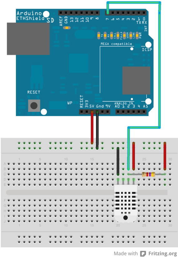
Figure 3-20. Wiring the DHT22
Next, connect the power from the Arduino to the breadboard. Use one jumper wire to connect the 5V pin on the Arduino to the breadboard power rail and another for the ground (GND) pin on the Arduino to the ground rail on the breadboard. With these wires in place, you are ready to wire the sensor. You use three of the four pins, as shown in Table 3-1.
Table 3-1. DHT22 Connections
Pin |
Connected to |
|---|---|
1 |
+5V, 4.7K resistor between the power supply and the data pin (strong pullup) |
2 |
Pin 7 on Arduino, 4.7K resistor |
3 |
No connection |
4 |
Ground |
Next, connect the ground and power of the sensor to the breadboard power and ground rails. Then connect one wire from the data pin on the sensor to pin 7 of the Arduino. There is one last connection: you use a pull-up resistor of 4.7K Ohm connected to the data wire and the power rail of the breadboard.
To use the DHT22 with an Arduino, you need to have the latest DHT22 library. You can find the library at https://github.com/ringerc/Arduino-DHT22. You must download the library and place it in your Arduino libraries folder.
![]() Tip The Arduino libraries folder is generally found in your documents folder. See http://arduino.cc/en/Guide/Libraries for more information concerning your platform. For example, on Windows, the folder is named libraries versus Libraries.
Tip The Arduino libraries folder is generally found in your documents folder. See http://arduino.cc/en/Guide/Libraries for more information concerning your platform. For example, on Windows, the folder is named libraries versus Libraries.
To download the library, click the Download ZIP button, save the file, and then unzip it. The folder that is created has an unusual name: Arduino-DHT22-master. You must rename it to something like DHT22 to remove the dashes so the Arduino environment won’t complain. If your Arduino environment is running when you copy the folder, you need to restart it for the Arduino environment to read the new library.
Now that you have the hardware configured and the DHT22 library set up, let’s write some code!
Writing the Sketch
Recall that I mentioned the DHT22 has its own protocol for communicating data. It uses a number of different values as the first byte sent, in what is referred to as an error code. Several types of errors can occur, including the trivial case where there is no error. Table 3-2 lists the various error codes and their meanings (what action you should take).
Table 3-2. DHT22 Error Codes
Error Code |
Cause or Recommended Action |
|---|---|
DHT_ERROR_CHECKSUM |
Checksum failed. Could indicate read/send errors. Values read may not be accurate. |
DHT_BUS_HUNG |
Error reading from sensor. Try again at the next cycle. |
DHT_ERROR_NOT_PRESENT |
Cannot communicate with the sensor. Check the wiring. |
DHT_ERROR_ACK_TOO_LONG |
Too long between data sent and acknowledgement. Try again at the next cycle. |
DHT_ERROR_SYNC_TIMEOUT |
Synchronization failure during read. Try again at the next cycle. |
DHT_ERROR_DATA_TIMEOUT |
Timeout sending data. Try again at the next cycle. |
DHT_ERROR_TOOQUICK |
Wait at least 2 seconds between reads. |
DHT_ERROR_NONE |
No error. Read values. |
As you can see in the table, most error conditions are related to read errors. The DHT22 is a rather slow device, so you should not try to read values more often than every 2 minutes. Also, some of the errors can have additional data that you can read. For example, the checksum error still contains the values sent, but they may be invalid.
I mentioned that the DHT22 sensor had its own protocol. What you see in Table 3-2 is only a small part of that protocol: the part you must include in your sketch. However, there is much more going on in the DHT library. If you are curious, open the DHT library with your Arduino IDE and explore the methods. Only then will you get a taste of what the protocol for reading from the sensor is really like.
What you have so far is the need to read from the sensor and interpret its error code. To do this, you use a switch statement (a shorter form of if/else if). To make the code easier to read and easier to maintain, place this code in a separate function called read_data(). Listing 3-2 shows the completed method.
Listing 3-2. The read_data() Method
void read_data() {
  DHT22_ERROR_t errorCode;

  errorCode = myDHT22.readData();
  switch(errorCode)
  {
    case DHT_ERROR_NONE:
      char buf[128];
      sprintf(buf, "%hi.%01hi, %i.%01i",
                   myDHT22.getTemperatureCInt()/10,
                   abs(myDHT22.getTemperatureCInt()%10),
                   myDHT22.getHumidityInt()/10,
                   myDHT22.getHumidityInt()%10);
      Serial.print("Data read:");
      Serial.print(buf);
      break;
    case DHT_ERROR_CHECKSUM:
      Serial.print("check sum error ");
      Serial.print(myDHT22.getTemperatureC());
      Serial.print("C ");
      Serial.print(myDHT22.getHumidity());
      Serial.println("%");
      break;
    case DHT_BUS_HUNG:
      Serial.println("BUS Hung ");
      break;
    case DHT_ERROR_NOT_PRESENT:
      Serial.println("Not Present ");
      break;
    case DHT_ERROR_ACK_TOO_LONG:
      Serial.println("ACK time out ");
      break;
    case DHT_ERROR_SYNC_TIMEOUT:
      Serial.println("Sync Timeout ");
      break;
    case DHT_ERROR_DATA_TIMEOUT:
      Serial.println("Data Timeout ");
      break;
    case DHT_ERROR_TOOQUICK:
      Serial.println("Polled too quick ");
      break;
  }
}
Notice at the top of the method that you call the DHT library method read_data(). You instantiate an object named myDHT22 in the preamble of the sketch. Following that, you use a switch statement and include each of the error codes, taking specific action for each. In the case of the DHT_ERROR_NONE (no error) result, you format the data for sending to the serial monitor.
The serial monitor is a special window (dialog) that you can use to send messages from your sketch. In Listing 3-2, every call to Serial.print() and Serial.println() results in a message being shown in the serial monitor. You can open the serial monitor after a sketch is uploaded by clicking the button at upper right in the Arduino IDE sketch window.
Notice for the DHT_ERROR_NONE case that you simply build a string from a static buffer of size 128 using the sprintf()6 method to format and populate the values for display. Once you have all the code entered into your Arduino environment and your Arduino is ready to go, it is time to try it out.
![]() Caution Watch out for array sizes! If you intend to save character string data returned by sensor nodes, be sure your data will fit into memory (buf).
Caution Watch out for array sizes! If you intend to save character string data returned by sensor nodes, be sure your data will fit into memory (buf).
I mentioned needing to instantiate an object in the preamble. You also need to include the DHT library and supporting files. The following shows the statements needed. Here you include the SPI and DHT22 library header files, define the data pin for the sensor as pin 7 on the Arduino, add a delay constant of 5 seconds, and instantiate an instance of the DHT class:
#include <SPI.h>
#include <DHT22.h>
#define DHT22_PIN 7       // DHT2 data is on pin 7
#define read_delay 5000   // 5 seconds
DHT22 myDHT22(DHT22_PIN); // DHT22 instance
The setup() method is where you initiate the serial monitor. The workings of the sketch in the loop() method are also simplistic. Here you wait for the delay period defined and then read the data by calling your read_data() method. Recall that the Arduino will execute these two statements until it is powered down. Listing 3-3 shows the completed sketch.
Listing 3-3. Completed Sketch: Reading a DHT-22 Sensor
/*
  Sensor Networks Example Arduino Hosted Sensor Node

  This sensor node uses a DHT22 sensor to read temperature and humidity
  printing the results in the serial monitor.

*/
#include <SPI.h>
#include <DHT22.h>

#define DHT22_PIN 7       // DHT2 data is on pin 7

#define read_delay 5000   // 5 seconds

DHT22 myDHT22(DHT22_PIN); // DHT22 instance

void read_data() {
  DHT22_ERROR_t errorCode;

  errorCode = myDHT22.readData();
  switch(errorCode)
  {
    case DHT_ERROR_NONE:
      char buf[128];
      sprintf(buf, "%hi.%01hi, %i.%01i
",
                   myDHT22.getTemperatureCInt()/10,
                   abs(myDHT22.getTemperatureCInt()%10),
                   myDHT22.getHumidityInt()/10,
                   myDHT22.getHumidityInt()%10);
      Serial.print("Data read:");
      Serial.print(buf);
      break;
    case DHT_ERROR_CHECKSUM:
      Serial.print("check sum error ");
      Serial.print(myDHT22.getTemperatureC());
      Serial.print("C ");
      Serial.print(myDHT22.getHumidity());
      Serial.println("%");
      break;
    case DHT_BUS_HUNG:
      Serial.println("BUS Hung ");
      break;
    case DHT_ERROR_NOT_PRESENT:
      Serial.println("Not Present ");
      break;
    case DHT_ERROR_ACK_TOO_LONG:
      Serial.println("ACK time out ");
      break;
    case DHT_ERROR_SYNC_TIMEOUT:
      Serial.println("Sync Timeout ");
      break;
    case DHT_ERROR_DATA_TIMEOUT:
      Serial.println("Data Timeout ");
      break;
    case DHT_ERROR_TOOQUICK:
      Serial.println("Polled too quick ");
      break;
  }
}

void setup() {
  Serial.begin(115200);  // Set the serial port speed
}

void loop() {
  delay(read_delay);
  read_data();
}
Open a new Arduino sketch by clicking the New menu button or by choosing File ![]() New. Now you can compile, upload, and test the project.
New. Now you can compile, upload, and test the project.
Executing the sketch means uploading it to your Arduino and watching it run. If you haven’t connected your Arduino, you can do that now.
I like to begin by compiling the sketch. Click the check mark on the left side of the Arduino application, and observe the output in the message screen at the bottom. If you see errors, fix them and retry the compile. Common errors include missing the DHT22 library (which may require restarting the Arduino application), typing errors, syntax errors, and the like. Once everything compiles correctly, you are ready to upload your sketch by clicking the Upload button on the toolbar.
Right after the upload completes, open the serial monitor by clicking the button at right on the toolbar. Observe the Arduino messages. Figure 3-21 shows the typical output you should see.
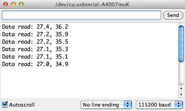
Figure 3-21. Serial monitor output for the DHT22 sensor project
If you see similar output, congratulations! You have just built your first Arduino-hosted sensor node. This is an important step in building your sensor network, as you now have the tools needed to start building more sophisticated, wireless sensor nodes and aggregate nodes for recording sensor data.
Let’s take the Arduino sensor experience one step further and add XBee modules to enable the sensor to be placed away from the Arduino. This effectively demonstrates how an Arduino can remotely host a number of sensor nodes and thus become an aggregate node in a sensor network.
Project: Using an Arduino as a Data Collector for XBee Sensor Nodes
This project combines what you have learned about the Arduino in this chapter and the XBee in Chapter 2. More specifically, you use an Arduino and a remote sensor that connects the sensor with the Arduino using XBee modules. But first, let’s build the XBee sensor node and test it with your laptop before you build the Arduino component.
XBee Sensor Node
The XBee sensor node is a single XBee module with a simple sensor connected to one of the analog input pins. For this project, you tell the XBee to send data using short time periods; but for a real project, you would want to consider using a slower sampling rate or perhaps using sleep mode, in which the XBee sleeps for some time then sends data, and repeats. We set the sampling rate when we configure the XBee module later in this chapter. For now, let’s let the XBee send samples more frequently so you can see something happening.7
The XBee has a really nifty feature for monitoring battery power. You can tell the XBee to send the current supply power as part of the data packet. In this case, it sends whatever voltage is being supplied to the XBee. This is really neat because it allows you to build in to your solution a trigger to remind you to change the batteries in your sensor node(s). If you have a home or apartment with smoke detectors, you may have already experienced a similar circuit. For those of us with homes that have multiple smoke detectors, it can be somewhat of a “Where’s Waldo?” game to find the detector that is chirping! This is why whenever six months go by or the first detector starts chirping, I change the batteries in all of them.
To keep the project easy to build, you use a breadboard for the sensor node. Once you have built a few sensor nodes, you can move them to PCB breadboards for semi-permanent installation or perhaps design and build your own custom PCB for your sensor nodes.
The hardware for the XBee sensor node consists of a breadboard, a breadboard power supply, a TMP36 temperature sensor, and a 0.10μF capacitor. You also need an XBee explorer board and a set of male headers (0.1" spacing for breadboards) like those available from Adafruit or SparkFun. Figure 3-22 shows the SparkFun regulated explorer board. The regulated board is a bit more expensive, but it has power regulation built in so if you accidentally connect 5V it won’t fry your XBee. As an owner of a now completely useless XBee (it’s not even big enough to use as a coaster), I can tell you that it is worth the extra cost.

Figure 3-22. SparkFun regulated XBee explorer (courtesy of SparkFun)
![]() Note Most breakout boards do not come with the breadboard headers installed. You have to solder them yourself, get someone to do it for you, or, with some careful shopping, find another board that is already assembled.
Note Most breakout boards do not come with the breadboard headers installed. You have to solder them yourself, get someone to do it for you, or, with some careful shopping, find another board that is already assembled.
Once you have the components assembled, plug them in to your breadboard as shown in Figure 3-23. Be sure to set the breadboard power supply to 3.3V.

Figure 3-23. XBee temperature sensor node
There is no need to install the XBee module just yet. You need to configure its settings. You do that in the next section.
It is important to note that the drawing shows positive power going to pin 1 of the XBee. Be sure to check the pins on your breakout board to be certain you are connecting to the right pin. For example, the SparkFun regulated explorer input voltage is not on pin 1.
![]() Note The breadboard power supply can be any 6V to 12V power supply. The 9V wall wart that most use to power their Arduino will do nicely.
Note The breadboard power supply can be any 6V to 12V power supply. The 9V wall wart that most use to power their Arduino will do nicely.
Notice that you also connect your data line from the TMP36 to pin 17 (analog 3) on the XBee, and you connect ground to the ground pin on the breakout board (or explorer). Be sure to orient the TMP36 with the flat side as shown in the drawing. That is, with the flat side facing you, pin 1 is on the left and is to be connected to input power, the middle pin is data, and pin 3 is to be connected to ground. You can place the capacitor in either orientation, but be sure it is connected to pin 1 and 3 of the TMP36.
![]() Caution If your breakout board power supply allows for multiple settings, make sure it is set on 3.3V! More than that may do harm to your XBee. Can you guess how I figured that out?
Caution If your breakout board power supply allows for multiple settings, make sure it is set on 3.3V! More than that may do harm to your XBee. Can you guess how I figured that out?
ALTERNATIVE TO A BREADBOARD POWER SUPPLY
If you plan to make a few XBee sensor nodes for semi-permanent installation, you may not want to use a breadboard. Rather, you may want to use a PCB breadboard and solder your XBee breakout board, sensor, and supporting electronics in place. In this case, a breadboard power supply might not be convenient. Similarly, if you want to keep costs down, you can build a basic power supply from a few parts that can accept up to 12V and still regulate the power to your XBee at 3.3V.
All you need are a 7833-voltage regulator, a 1μF capacitor, a 10μF, and a 2-terminal terminal block (or similar power connector). In total, you should be able to buy these components for a few dollars even at an electronics retail store—and less from an electronics online store. Arranging the circuit is easy. The following picture shows the components wired to a breadboard.

You need only a little imagination and some wire to transfer the circuit to a PCB breadboard. Notice the orientation of the capacitors—keep the white strip on the negative side!
![]() Caution Be sure to double-check your wiring before powering on the sensor node.
Caution Be sure to double-check your wiring before powering on the sensor node.
The XBee module you use on the XBee sensor node is either an end device or a router with API firmware. You use the X-CTU application to connect to the XBee with a USB adapter. From the Modem Configuration tab, you can load the firmware as well as make modifications to the AT parameters.
In this case, you want the XBee module to send data every 15 seconds (15,000 milliseconds), read data on analog line 3, and send you the reference voltage. Thus, in the X-CTU application, you want to change the corresponding values using hexadecimal numbers. Table 3-3 shows the values you need to change. Recall that all values are entered in hexadecimal and that you can change the value in X-CTU by first clicking the row that corresponds to the setting.
Table 3-3. XBee Options and Values

Open the X-CTU application on your Windows machine, and load the API firmware for an XBee module. You can use one of the modules you used in Chapter 2, provided you don’t use the coordinator. You will use that module to test the XBee sensor node. Change the settings as shown, and then click Write to save the settings to the XBee module.
To test the XBee sensor node, you use your XBee coordinator with API firmware installed on the USB adapter. Do this first so the coordinator can be up and running when you start the XBee sensor node. Plug it in to your computer, and open a terminal application with the display set to show hexadecimal values.
Next, connect your power supply to your XBee sensor node. It will take a few moments for the XBee to connect to the coordinator and join the network. Once it does, you start to see the coordinator receiving data, as shown in Figure 3-24.

Figure 3-24. Serial monitor output
You should see an I/O data sample receive (Rx) Indicator packet. Notice in the image that the first row begins with 7E (hex). This is the start-of-packet delimiter. Search ahead until you find the next 7E value. The values from the start delimiter to the value before the next start delimiter make up the data packet from the XBee temperature sensor node. Table 3-4 decodes the first sample packet in the example.
Table 3-4. IO Data Sample Rx Indicator Packet
Value |
Field Name |
Notes |
|---|---|---|
7E |
Start delimiter |
|
00 14 |
Packet length |
20 bytes to checksum |
92 |
Frame type |
I/O Data Sample Rx Indicator |
00 13 A2 00 40 90 29 DB |
64-bit address |
Address of XBee sensor node |
3E 60 |
16-bit address |
|
02 |
Options |
|
01 |
Number of samples |
1 data sample |
00 00 |
Digital mask |
Digital pins that have data |
88 |
Analog mask |
Analog pins that have data |
02 6E |
Sample |
Temperature from sensor |
0A D4 |
Supply voltage |
|
93 |
Checksum |
![]() Note If you used the newer version 2.5 firmware, you may see slightly different codes for the options byte, but the important ones to look for are sample and voltage values.
Note If you used the newer version 2.5 firmware, you may see slightly different codes for the options byte, but the important ones to look for are sample and voltage values.
This data packet represents the data sent from the XBee. In this case, you set the XBee to send any value from the analog pin 3 every 15 seconds. You also set the option to send the value of the supply voltage. Notice the value for the analog mask: the value 88 in hexadecimal is converted to 1000 1000 in binary. The first part of the byte is an indicator that the supply voltage is also included in the data packet. The second part of the byte indicates that AD3 (pin 3) was the source of the sample. If you were sampling multiple sensors, the mask would have the bits for the data pin set or 0001 for pin 0, 0010 for pin 1, and 0100 for pin 2.
From the table, you see there is indeed one data sample with a value of 02 6E (hex, 622 decimal). The value is 622 because this is the voltage in millivolts read from the sensor. To calculate the temperature, you must use the following formula:
temp = ((sample * 1200/1024) - 500)/10
Thus, you have ((622 * 1200/2400)-500)/10 = 22.89 degrees Celsius. The supply voltage is a similar formula:
voltage = (sample * 1200/1024)/1000
Here you convert the data read to volts rather than millivolts. Thus, the data packet contained 0A D4 (hex, 2772), and the voltage read is 3.24 volts. If you are powering an XBee sensor from a battery, you can use this value to determine when you need to change or charge the battery.
Take a few moments to study the other samples in the example and check the data samples for the temperature read. Once you are convinced your XBee sensor node is sending similar data, you can conclude that the sensor node is working correctly. Now that you have a working, tested sensor node, let’s set up your Arduino to receive the information remotely.
Arduino with XBee Shield
You can use an Arduino to read the data from the XBee sensor node. This gives you an example of using an Arduino as a data aggregator (collector) of sensor data from XBee sensor nodes. Let’s set up an Arduino with an XBee. This project demonstrates using an Arduino to receive data via XBee, but you can also send data via XBee.
The sample setup in this section uses a typical Arduino (Uno, Leonardo, etc.) that supports standard shields. Although it is not expressly necessary to use a shield designed to accept an XBee module, most XBee shields are designed to make the use of the XBee easier. In other words, you don’t have to worry about how to wire the XBee to the Arduino. Figure 3-25 shows an Arduino with an XBee shield from SparkFun.

Figure 3-25. Arduino XBee shield (courtesy of SparkFun)
I use this shield to demonstrate how to communicate with an XBee module. If you decide to use another shield, be sure to check that shield’s documentation for examples of how to use it and compare it with the code in this project. Make the appropriate modifications (hardware connections and changes to the sketch) so that your project will work correctly with your shield.
The shield lets you choose to communicate with the Arduino with the onboard serial circuitry (UART8) for the Arduino via digital pins 0 and 1. But these are also the pins used when communicating with the Arduino via USB from the Arduino IDE. Fortunately, the SparkFun XBee shield has a small switch that allows you to choose to use pins 2 and 3 instead. You use this option so that you can write a script to read data from the shield via the XBee and still connect to the Arduino IDE and use the serial monitor. But there is a catch: only one UART is available. You must use the software serial library to simulate a second serial connection. The software serial library is included in the Arduino IDE. You see how to do this in the “Software Setup” section.
![]() Tip If you are using a different XBee shield, you should consult the documentation on the shield and use the pins as instructed. Some shields are hard wired.
Tip If you are using a different XBee shield, you should consult the documentation on the shield and use the pins as instructed. Some shields are hard wired.
If you do not want to use a shield, you can wire your XBee to an Arduino as you did earlier. In this case, you use an XBee breakout board from SparkFun to mate to a breadboard. Figure 3-26 shows the wiring diagram for wiring the XBee regulated explorer breakout board to an Arduino. Notice that you use the 5V pin from the Arduino. If you are using a nonregulated breakout board, you should use the 3.3V pin instead. Always double-check the maximum voltage of any component you use before powering on the project.
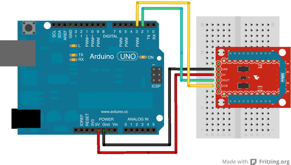
Figure 3-26. Connecting an XBee to an Arduino via a SparkFun XBee breakout board
![]() Note Either of these methods will work for this project.
Note Either of these methods will work for this project.
Whichever method you choose, take the XBee coordinator module off your USB adapter and insert it into the XBee shield or the XBee regulated explorer breakout board. Now that the hardware is ready, let’s set up your Arduino environment and write a sketch to read the data from the XBee sensor node.
Software Setup
The XBee communicates via a serial connection. Although you can write your own communication statements to communicate with an XBee, there is an easier way. Andrew Rapp has written a library that encapsulates communication with an XBee module. The library is called XBee Arduino and can be found at http://code.google.com/p/xbee-arduino/.
To get started, download version 0.4 of the XBee library, unzip it, and copy it to your Arduino library folder. You can find the name of the library by checking the options for your Arduino IDE. You can determine where this is by examining the preferences for the Arduino environment, as shown in Figure 3-27. For example, my sketches folder on my Mac is /Users/cbell/Documents/Arduino. Thus, I copied the XBee library to a folder named /Users/cbell/Documents/Arduino/Libraries/XBee.
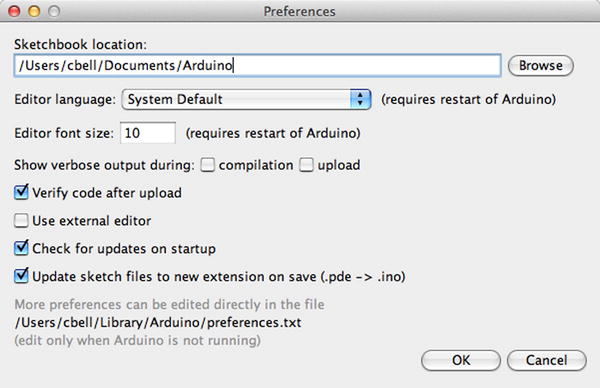
Figure 3-27. Arduino Preferences dialog
![]() Tip If you copy a library to your libraries folder while the Arduino application is running, you must restart the application to detect the new library.
Tip If you copy a library to your libraries folder while the Arduino application is running, you must restart the application to detect the new library.
Once the library is installed and you have restarted your Arduino IDE, you can write the script to read the data from the XBee. The library has classes for each of the popular XBee data packets to send and receive data to or from an XBee. This project uses the IO sample class because you know that is the only packet we are interested in using in this project.
You need to create several parts of the sketch. Using the XBee library is easier than writing your own communication methods, but the library has certain setup steps and methods you need to use to read the data packet.
To begin, let’s include the library headers for the XBee and software serial libraries. Recall that the software serial library is part of the Arduino IDE:
#include <XBee.h>
#include <SoftwareSerial.h>
Now you must define the pins you use to communicate to the XBee module. You use the serial monitor as an output device, so you need to use alternative pins. In this case, you use pins 2 and 3 for the receive and transmit connections. You need to define these and initialize the software serial library and use that to communicate to the XBee. The following shows the definitions needed:
uint8_t recv = 2;
uint8_t trans = 3;
SoftwareSerial soft_serial(recv, trans);
Next, you must instantiate the XBee library and helper classes. In this case, you need the helper class for the I/O data sample packet:
XBee xbee = XBee();
ZBRxIoSampleResponse ioSample = ZBRxIoSampleResponse();
Now we are ready to write the startup code. For this project, you must initiate the software serial library and pass that to the XBee library for use in communicating with the XBee module. You also need to initialize the default serial class so that you can use print() statements to display the data read in a later portion of the code. Listing 3-4 shows the complete setup() method.
Listing 3-4. Arduino XBee setup() Method
void setup() {
  Serial.begin(9600);
  while (!Serial);   // Leonardo boards need to wait for Serial to start
  soft_serial.begin(9600);
  xbee.setSerial(soft_serial);
}
Notice the line with the while loop. You need to add this for use on Leonardo boards. If you omit this and run the sketch on a Leonardo board, the XBee may fail to work. Add this loop to allow the Leonardo time to start the Serial instance.
Now let’s code the methods you use to read the data from the packet. You learn how to read the packet from the XBee a bit later. First, let’s examine how to get the source address for the data packet. Listing 3-5 shows the code for doing so.
Listing 3-5. Arduino XBee get_address() Method
void get_address(ZBRxIoSampleResponse *ioSample) {
  Serial.print("Received data from address: ");
  Serial.print(ioSample->getRemoteAddress64().getMsb(), HEX);
  Serial.print(ioSample->getRemoteAddress64().getLsb(), HEX);
  Serial.println("");
}
Notice that you simply use the ioSample class instance and call the method getRemoteAddress64().getMsb(). Actually, this is a call to a subclass (RemoteAddress64) and its method getMsb(). This returns the most significant byte (high 16 bits) of the 64-bit address. You do the same for the least significant bit with the getRemoteAddress64().getLsb() call. You then print these values, specifying that you want to print them in hexadecimal. If you were reading data from multiple XBee nodes, it would be handy to apply a name to each address, such as “bedroom” or “living room”. I leave that for you as an exercise.
Next you want to read the data payload. In this case, you want to read the temperature data sent to the XBee coordinator from the XBee sensor node. Listing 3-6 shows the code needed to do this. You use the formulas discussed previously to convert the millivolt value read by the sensor to temperature in Celsius and then convert that to Fahrenheit.
Listing 3-6. Arduino XBee get_temperature() Method
void get_temperature(ZBRxIoSampleResponse *ioSample) {
  float adc_data = ioSample->getAnalog(3);

  Serial.print("Temperature is ");
  float temperatureC = ((adc_data * 1200.0 / 1024.0) - 500.0) / 10.0;
  Serial.print(temperatureC);
  Serial.print("c, ");
  float temperatureF = ((temperatureC * 9.0)/5.0) + 32.0;
  Serial.print(temperatureF);
  Serial.println("f");
}
Finally, you need to read the supply voltage from the data packet. In this case, the supply voltage appears after the data samples. Because you know there is only one data sample (via the analog sample mask), you know that the analog voltage appears right before the checksum. Sadly, there is no method currently to fetch that information from the I/O sample packet in the XBee library. However, all is not lost, because the author of the library stores the data in an array and has supplied a subclass for you to use to fetch the raw data. In this case, you want bytes 17 (most significant byte) and 18 (least significant byte) from the data. You know these are the indexes needed by counting from the byte following the frame type starting from zero. See Table 3-4 for details.
Like the temperature data, you must convert the value read to volts using the formula discussed previously. Listing 3-7 shows the code needed to read, convert, and display the supply voltage for the XBee sensor node. Notice that you shift the most significant byte 8 bits so that you can preserve the 16-byte floating-point value.
Listing 3-7. Arduino XBee get_supply_voltage() Method
void get_supply_voltage() {
  Serial.print("Supply voltage is ");
  int ref = xbee.getResponse().getFrameData()[17] << 8;
  ref += xbee.getResponse().getFrameData()[18];
  float volts = (float(ref) * float(1200.0 / 1024.0))/1000.0;
  Serial.print(" = ");
  Serial.print(volts);
  Serial.println(" volts.");
}
Take some time to examine the calculations. In this example, you convert the voltage read and sent by the XBee sensor node to Celsius and then again to Fahrenheit. You also convert the supply voltage to volts for easier reading. All these values are sent to the serial monitor for feedback during testing.
Once you have those methods implemented, you place the code to read the data from the XBee in the loop() method, calling these methods to decipher the data and print it to the serial monitor.
Because this loop() method is called repeatedly, you use the XBee class method to read the packet and then determine if the packet is the I/O data sample packet. If it is, you read the data from the packet. If it is not, you add some simple error handling so that the Arduino can continue to read data rather than stop. Listing 3-8 shows the completed loop() method.
Listing 3-8. Arduino XBee loop() Method
void loop() {
  xbee.readPacket();

  if (xbee.getResponse().isAvailable()) {

    if (xbee.getResponse().getApiId() == ZB_IO_SAMPLE_RESPONSE) {
      xbee.getResponse().getZBRxIoSampleResponse(ioSample);
      // Read and display data
      get_address(&ioSample);
      get_temperature(&ioSample);
      get_supply_voltage();
    }
    else {
      Serial.print("Expected I/O Sample, but got ");
      Serial.print(xbee.getResponse().getApiId(), HEX);
    }
  } else if (xbee.getResponse().isError()) {
    Serial.print("Error reading packet.  Error code: ");
    Serial.println(xbee.getResponse().getErrorCode());
  }
}
Notice that in the code you check to see whether the packet is available; if it is, you read it. If the packet read is the right frame type, in this case ZB_IO_SAMPLE_RESPONSE, you read the data from the packet and display it. If it isn’t the right packet, you print out to the serial monitor the frame type of the packet received. If there is an error reading the packet, you capture that in the last else and display the error to the serial monitor.
Notice the contents of the block of code for the ZB_IO_SAMPLE_RESPONSE condition. You begin by initializing the I/O data sample class with the data read, then read the address of the XBee that sent the packet, and then perform the calculations for temperature and reference voltage.
Once you understand the code so far, start a new file and type the information into your new sketch window. Listing 3-9 shows the completed sketch for the Arduino XBee receiver project. This code is also available on the Apress site at the source code link for this book.
Listing 3-9. Arduino XBee Receiver
/**
  Sensor Networks Example Arduino Receiver Node

  This project demonstrates how to receive sensor data from
  an XBee sensor node. It uses an Arduino with an XBee shield
  with an XBee coordinator installed.

  Note: This sketch was adapted from the examples in the XBee
  library created by Andrew Rapp.
*/

#include <XBee.h>
#include <SoftwareSerial.h>

// Setup pin definitions for XBee shield
uint8_t recv = 2;
uint8_t trans = 3;
SoftwareSerial soft_serial(recv, trans);

// Instantiate an instance of the XBee library
XBee xbee = XBee();

// Instantiate an instance of the IO sample class
ZBRxIoSampleResponse ioSample = ZBRxIoSampleResponse();

void setup() {
  Serial.begin(9600);
  while (!Serial);   // Leonardo boards need to wait for Serial to start
  soft_serial.begin(9600);
  xbee.setSerial(soft_serial);
}

// Get address and print it
void get_address(ZBRxIoSampleResponse *ioSample) {
  Serial.print("Received data from address: ");
  Serial.print(ioSample->getRemoteAddress64().getMsb(), HEX);
  Serial.print(ioSample->getRemoteAddress64().getLsb(), HEX);
  Serial.println("");
}

// Get temperature and print it
void get_temperature(ZBRxIoSampleResponse *ioSample) {
  float adc_data = ioSample->getAnalog(3);

  Serial.print("Temperature is ");
  float temperatureC = ((adc_data * 1200.0 / 1024.0) - 500.0) / 10.0;
  Serial.print(temperatureC);
  Serial.print("c, ");
  float temperatureF = ((temperatureC * 9.0)/5.0) + 32.0;
  Serial.print(temperatureF);
  Serial.println("f");
}

// Get supply voltage and print it
void get_supply_voltage() {
  Serial.print("Supply voltage is ");
  int ref = xbee.getResponse().getFrameData()[17] << 8;
  ref += xbee.getResponse().getFrameData()[18];
  float volts = (float(ref) * float(1200.0 / 1024.0))/1000.0;
  Serial.print(" = ");
  Serial.print(volts);
  Serial.println(" volts.");
}

void loop() {
  //attempt to read a packet
  xbee.readPacket();

  if (xbee.getResponse().isAvailable()) {
    // got something

    if (xbee.getResponse().getApiId() == ZB_IO_SAMPLE_RESPONSE) {

      // Get the packet
      xbee.getResponse().getZBRxIoSampleResponse(ioSample);

      // Read and display data
      get_address(&ioSample);
      get_temperature(&ioSample);
      get_supply_voltage();
    }
    else {
      Serial.print("Expected I/O Sample, but got ");
      Serial.print(xbee.getResponse().getApiId(), HEX);
    }
  } else if (xbee.getResponse().isError()) {
    Serial.print("Error reading packet.  Error code: ");
    Serial.println(xbee.getResponse().getErrorCode());
  }
}
Take some time to ensure that the sketch compiles before you upload it to your Arduino. Remember, once the sketch is uploaded, it begins to run.
Testing the Final Project
To test the project, ensure that you start your Arduino first and then the XBee sensor node. Start the Arduino, upload the sketch, and then turn on the serial monitor. You should observe the link lights on the XBee regulated breakout board flicker as the XBee node is accepted by the coordinator on the Arduino and added to the network. Within about 5 seconds, the XBee sensor node begins sending data. When this occurs, the Arduino sketch should start printing statements to your serial monitor. Figure 3-28 shows an example of the output you should see in the serial monitor.

Figure 3-28. Serial monitor output
Did you see something similar? If so, you’re doing great work and now have the rudimentary components to build sensor nodes and Arduino-based sensor data aggregators.
If you do not see any output in the serial monitor, do not panic. Instead, double-check that the XBee on your Arduino is plugged in correctly and that you are using the correct pins in the sketch that correspond to how the XBee shield you are using connects to the Arduino (not all shields use pins 2 and 3 like the SparkFun shield). Hint: check the documentation for your shield.
If all that is correct, make sure you are using the coordinator API firmware on the XBee connected to the Arduino and the router API firmware on the XBee sensor node. If you are still having issues, step back to the previous project to ensure that the sensor node is still working.
You can also try turning off both the Arduino and the XBee sensor node; then turn on the Arduino, wait about 10 seconds, and turn the XBee sensor node back on. Sometimes the handshake process and network join can stall, and nothing happens for a while. Turning an XBee off and back on in this order ensures that it will reattempt to configure.
On the other hand, maybe you are getting data, but it is not correct—the temperature read is far too low for the actual environment. I had this happen once when the wire I was using to connect to the data pin on the TMP36 was accidentally removed. The bottom line is, always check and recheck your wiring.
For More Fun
If you would like to expand the project, you can add a second XBee sensor node and modify the Arduino sketch to supply a location for each node. For example, you could label one node “office” and the other “kitchen”. The sketch should record (write to the serial monitor) the location of the sensor along with the sensor data from the XBee.
A number of components are needed to complete the projects in this chapter. They are listed in Table 3-5.
Table 3-5. Components Needed

Summary
This chapter covered a lot of ground. You explored the Arduino platform, including the many forms available and how to write sketches (programs) to control the Arduino. I also showed you how to host sensors with the Arduino by using a temperature and humidity sensor.
You applied the information you learned about the XBee in Chapter 2 to create an XBee sensor node to read temperature data. You then set up an Arduino with an XBee coordinator to receive the sensor data from the XBee sensor node and display it in the serial monitor.
In the next chapter, you learn about the Raspberry Pi and discover how to use the I/O pins on the Raspberry Pi to read data from sensors.
1Meaning it is designed for a small, specific set of functionality.
2For a complete description of the Arduino.cc license policies and more information about building and selling your own Arduino-compatible board, see http://arduino.cc/en/Main/FAQ.
3Compare Figures 3-2 and 3-3. Notice how much larger the Due is than the Uno. If you choose to incorporate a Due, Mega, or similar board, you may have to set aside more room to mount the board.
4Which means “2009” in Italian.
5At least, I have not found anyone who has done this successfully.
6A very commonly used method. See the sprintf() documentation at www.cplusplus.com/reference/cstdio/sprintf/ for more details.
7It can sometimes be maddening to wait for an XBee that has an extended sleep cycle. It is best to not use sleep while you are prototyping the solution.
8http://en.wikipedia.org/wiki/Universal_asynchronous_receiver/transmitter