You'll reach an important milestone in this chapter-the completion of the CNC machine table. The table is the largest portion of your CNC machine, and if you've followed the instructions in Chapters 7 and 8, you're ready to finish up the work required to assemble it.
Later chapters in the book will have you cutting and drilling additional MDF pieces that will be added to the table. Keep in mind that the table is 2'×4' in size, so you'll want to put it somewhere in your work area that is easily accessible (preferably above waist level to make it easier to work on) while still allowing you some free room to measure, cut, and drill. You can certainly use the table surface for this kind of work, but just be careful not to drill or cut into the table surface or damage it by accidentally hitting it with other MDF parts.
We'll start by finishing up the drilling of the table's legs and then attach these legs to the table. When done, you can congratulate yourself on the successful completion of one-third of your final CNC machine.
You should have Parts T and U marked for drilling after completing Chapter 8. Before you begin drilling any holes, we'd like to draw your attention to the larger hole in the center of both pieces, as shown in Figure 9-1.

Note
Refer to the MDF Plans and Cut List PDF file for cutting and drilling dimensions of all MDF parts-this file can be downloaded at www.buildyourcnc.com/book.aspx
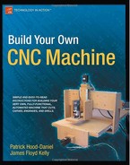
Don't worry about the drilling yet. Just take a look at Figure 9-2, which shows a closeup image of that larger center hole drilled. Notice that it consists of a smaller-diameter hole drilled completely through the piece of MDF and a larger-diameter hole drilled approximately halfway through the piece. This creates a shoulder, or shelf, that will be used to support a bearing that is inserted later in the building process. We'll explain how to drill this hole in more detail shortly.

Figure 9-2. The large center hole consists of a smaller-diameter hole within a larger-diameter hole.
For now, go ahead and drill the 1/4" holes in Parts U and T, as shown in Figure 9-3. (For best results, drill pilot holes using a 1/8" bit in all holes, including the larger center hole, before drilling the larger holes.)
These 1/4" holes are where you will insert 2" bolts to secure the legs to the tabletop. (These bolts will screw into cross dowels inserted into the holes drilled on the tabletop.)
Next, you're going to need to counterbore the larger hole first. The diameter of the larger hole is 1 1/8". Drill to approximately 3/8" depth. The easiest method for doing this is to use a Forstner bit. Figure 9-4 shows Part U with the larger-diameter hole drilled.


There are two things we'd like to point out about Figure 9-4. The first is that we've drilled the two 1/4" holes to the right and left of the larger hole. The second is the "dimple" in the center of the larger hole. This hole was created by drilling a pilot hole. The pilot hole not only helps a drill bit to self-center, but will also be useful to us when drilling the inner hole; without the pilot hole to guide us, it would be difficult to drill the inner hole centered in the larger outer hole.
The plans call for using a 1"-diameter bit to drill the inner hole. This will create an edge inside the larger hole of only 1/16" width. Figure 9-5 shows the final results of Part T. Perform the same actions on Part U.
Tip
While the 1/16" shoulder is sufficiently wide to support a bearing that will be inserted into the hole later, we used a 3/4" Forstner bit to create a slightly smaller inner hole but a larger shoulder (edge). Instead of a 1/16" shoulder inside the larger hole, we now have a 3/16" shoulder for the bearing to rest on.

Now, before you attach Parts T and U, you need to attach the 4' rail you cut in Chapter 8 that will attach to the sides of the table (Parts Y and Z). Go ahead and set Parts T and U aside for a moment and grab the two 4' lengths of aluminum angled rail.
Mark both pieces of 4' rail 3/4" from the ends. Drill 1/4" holes into the rails from the inside out, not the outside in. (You may find that drilling the holes using a slightly larger bit-5/16" is a good size-will allow for a little wiggle room for the inserted bolts to find the holes on the sides of the tabletop.)
Tip
You may wish to build a jig to hold the rail while drilling. One way to do this is to clamp two small pieces of waste MDF to the table (or drill press table) with a small 1/2" gap between the pieces. Place the rail in the gap so the inside edges are facing up for drilling. You can also secure the rail with another clamp to one or both of the scrap MDF pieces to keep it from moving.
Figure 9-6 shows a piece of 4' rail with one hole drilled 3/4" from the end.

After drilling two holes into a piece of rail, fit it into place over the chamfered edge of the tabletop and mark holes for drilling. Place a clamp on Parts Y and Z to hold the pieces tightly together, drill 1/4" holes into the sides of the chamfered edges, and use 2" bolts to bolt them to the tabletop using cross dowels inserted into the 7/16" holes on the tabletop surface.
Figure 9-7 shows the two pieces of 4' rail attached to the sides of the table. (A cross dowel is located inside the hole indicated by the arrow, but is just below the surface and not visible.)

After the rails are attached, it's time to attach the legs to the table.
All that's left is to connect one leg to each end of the table. Use six 2" bolts with six matching cross dowels per leg. Three bolts and three cross dowels will be used on the top and three bolts and three cross dowels will be used on the bottom. Figure 9-8 shows all six bolts connecting one leg to the table with the three cross dowels on top visible. (You may find it easier to screw in the bottom three bolts to the cross dowels by turning the table on its side.)

When your machine is done, it will use three different lengths of threaded rod to assist with the movement of the router-these are called lead screws. One piece of lead screw will be used for each axis, so you'll want to go ahead and purchase enough threaded rod to cut all three pieces. We recommend that you purchase one 8' length of 1/2"-diameter regular threaded rod with 13 threads per inch (TPI). If you can find a hardware store willing to cut them to the lengths required, consider yourself lucky; usually you'll need to purchase them in precut lengths and then cut them to your desired length later.
Tip
For our machine, we were able to use a single 8' rod to cut all three pieces. If you have to purchase the rod in shorter lengths, remember that the x-axis lead screw will be longer than 4', so try and purchase your lead screws in 6' or 8' lengths. The safest purchase will be to purchase a single 6' length and a 3' length if possible. The 6' length will be enough for the x-axis and z-axis lead screws, and the 3' length will be enough for the y-axis lead screw.
The length of the x-axis tabletop is 4' 1.5" (4 feet, 1.5 inches)-the lead screw will be inserted through two bearings inserted into the large holes drilled in Parts T and U. Mark and cut an extra 1" of lead screw protruding from both ends, as shown in Figure 9-9.
After cutting the x-axis lead screw to length (approximately 4' 3.5"), remove it from the machine and set it aside for later.

At this point, you should have the following items completed:
Rails attached to sides of tabletop
Parts T and U drilled with proper holes
Parts T and U mounted to the table
Lead screw for the x-axis cut to a length of approximately 4' 3.5"
For the work performed in this chapter, you will use:
1/4" pan head bolts; 2" length; quantity: 16
Cross dowels; quantity: 16
Lead screw option 1: 1/2"-diameter regular threaded rod; 13 TPI; 8'
Lead screw option 2: two 1/2"-diameter regular threaded rods; 13 TPI; 6' and 3'
You've completed the base of your CNC machine. All other work done in later chapters will build onto the table. Your x-axis is completed, so you're now ready to move on to the y-axis. Chapter 10 will get you started on a few of the parts needed to give your CNC machine the ability to move its mounted router front to back along the 4' rails you just mounted.