
Chapter 1

Keying Difficult Green Screen
Green screen, when well lit and well shot, can be a joy to work with. More often than not, however, green screen footage suffers from wrinkles, shadows, incomplete coverage, camera noise, and spill. Regardless, there is always a way to make the key work with common effects and tools available in layer-based and node-based compositing systems.
This chapter includes the following critical information:
• Chroma key terminology
• Common green screen problems and solutions
• Keying the foreground core and edge separately
• Keying without a green screen
Chroma Keying Overview
Chroma keying is the process by which a targeted color is converted to alpha transparency. The transparency allows the foreground to be placed over a new background. When discussing chroma keying, the background is the area you want to remove (by making it transparent) and the foreground is the area you want to keep (by making it opaque). Keying refers to the general process of chroma keying. A key is the end result of the keying process. Pulling a key is the process of keying. A key color is the background color you are targeting when keying. It’s also possible to target a specific non-RGB channel, such as hue (identifiable color separated from brightness), saturation (contrast between color channels), or luminance (gamma-adjusted brightness). Note that brightness and intensity are interchangeable when discussing compositing. A keyer is an effect or tool that offers one means to generate an alpha matte. An alpha matte is a grayscale representation of transparency and opaqueness within an alpha channel. A successful key allows you to avoid masking or rotoscoping, which is the manual definition of an alpha matte through the interactive creation of a spline shape.
Chroma keying was first developed for motion picture film, where elements were combined through optical printing. Due to the technical nature of film stock, blue was usually selected as a key color. With the advent of digital video, the color blue has been supplanted by the color green (which offers various technical advantages when processing digital video). That said, a key color can be any color. For example, if you are keying a blue and green peacock on a stage, you may make the key color red to make the key easier to pull. Nevertheless, when I refer to green screen in this book, I’m referring to the key color added to the location or set for the purpose of chroma keying.
Spill is the key color that has bounced onto the foreground (an undesired but common event). The interior or body or core of the foreground is the area up to, but not including, the foreground edge.
The State of Chroma Keying
In the near future, it’s quite possible that chroma key approaches using green screen, blue screen, and other key colors will no longer be necessary. For example, light field cameras, which capture light intensity and light direction, allow a compositor to remove background elements based on their distance from the camera at the time of capture. In addition, neural network image detection systems may advance to the point that foregrounds may be identified automatically with the system producing excellent edge fidelity.
Green Screen Problems and Solutions
Table 1.1 lists common problems encountered with green screen footage and potential solutions for creating a successful key.
Table 1.1
| Problem | Solution |
| Tracking marks Motion tracking tape marks are placed on the green screen. |
• Depending on the color of the tracking marks, you may be able to key the marks with a separate keying effect/tool. • If an additional key is not practical, rotoscoping is necessary. |
| Troubled green screen
• Insufficient green screen coverage (key color only covers part of background) • Heavy wrinkles in green screen fabric • Unwanted shadows on green screen • Unwanted lighting or rigging equipment in front of green screen |
Limit the area the key is operating on by adding a mask, either through rotoscoping or an internal matting process offered by the keying effect/tool. |
| Spill Spill color exists in the foreground. |
• Employ the spill suppression built into the keying effect/tool. • Add an additional, specialized spill suppression effect/tool. • Color grade the resulting foreground with color correction effects/tools to minimize the spill color. |
| Noise or grain Heavy noise or grain interferes with the success keying tools. |
• Pre-process the plate to reduce the noise or grain before applying the keyers. For example, add a blur or a noise reduction effect/tool. Some keyers , such as Keylight, carry built-in pre-processed softening options. • Apply different keyers or different keyer settings to different channels. For example, the blue channel may carry the heaviest amount of grain and may require slightly different settings. |
| Tricky foreground Foreground objects include glass, smoke, or sheer fabric. |
• Apply a secondary keyer. Programs generally include secondary keyers that are not good for general keying but may have specialized workflows that sometimes prove superior with tricky foregrounds. |
| Technology limitations Older video systems or current consumer video systems suffer from reduced resolution or artifacts such as edge bleeding. |
• Apply the approaches discussed for tricky foregrounds or complex foregrounds (see the following page). |
| Complex foreground Foregrounds with heavy motion blur, light-colors that carry heavy spill, or soft edges that disappear into the background. |
• Use additional matte effects/tools to fine-tune the matte edge after the application of the keyer. You can use the additional effect/tool to erode or soften the matte. You can also color grade the alpha channel. • Break the green screen into several parts using rotoscoping. For example, separate the head from the body and apply separate keying effects/tools to each part or apply separate keyer settings to each part. • Separate the foreground edge from the foreground core by rotoscoping or using an internal matting process offered by the keying effect/tool. |
| No green screen On occasion, it may be necessary to separate a foreground object even though no green screen or similar key color has been added to the background. |
• Rotoscoping is the standard solution. Although rotoscoping tools have become quite advanced, they may still require a tremendous amount of manual labor. • Depending on the footage, it may be possible to apply or create keyers by attacking background colors or special channels such as luminance. |
Keying Challenge A
Figure 1.1 shows a frame from the Dog.##.png image sequence. Table 1.2 describes the strengths and weaknesses of the footage in the context of chroma keying.

Figure 1.1 A green screen is placed behind a dog. Image sequence adapted from “Stock Footage – For the Dogs – Chroma Key Original 1” by Ivan Bridgewater and is licensed under Creative Commons Attribution 3.0 Unported (CC BY 3.0).
Table 1.2
| Strengths | Weaknesses |
| Green screen covers entire background. The green is not overexposed. | The green screen carries numerous wrinkles, which cause value variations in the green. There are two black lines at the left and right edge due to limitations of the camera. |
| The color contrast between the green of the green screen and the red fur of the dog makes the keying process easier. There is green spill along the dog’s belly, back, and ears but it’s not overly heavy. | The low resolution of SDTV footage makes the dog and the edges of the dog fur slightly soft. |
| The camera is static and the dog moves very little, which means there is practically no motion blur. | The wind blows the green screen fabric. |
| Video noise is relatively minimal. | The heaviest noise appears in the blue channel, yet the green channel noise adversely affects the foreground edge. |
Layer-Based Solution for Challenge A
You can key the dog footage with After Effects if you split the footage into multiple layers, tackle the foreground edge and foreground core separately, and reduce the inherent noise. With a layer- based program, layers are stacked with the highest layers occluding lower layers except where alpha transparency exists. Effects, which carry out various compositing tasks, are applied to specific layers.
Applying the Initial Key
The first step to keying a green screen is to add a minimal number of effects and adjust a minimal number of properties to see what potential problems exist. With After Effects, you can follow these steps:
1. Choose File > Import > File and import the Project-FilesPlatesDogDog.##.png image sequence. Create a composition that matches the resolution (720×540), duration (96 frames), and frame rate (30 fps) of the dog image sequence. Drop the sequence into the composition. Interpret the image sequence frame rate as 30 fps (RMB-click on the footage name, choose Interpret Footage > Main, and alter the Assume This Frame Rate field).
2. Add a Keylight effect (Effect > Keying > Keylight). Select the background color with the Screen Colour eyedropper. Select an average color within the green screen. The background is partially removed.
3. Experiment with different Screen Balance values. Lowering Screen Balance aggressively removes green from the foreground and shifts the colors to red-blue. Raising the Screen Balance lets more green survive and thus keeps the original foreground colors. In this case, set Screen Balance to 100.
4. Change the View menu to Screen Matte to see the alpha matte. To remove gray noise within the background, raise the Clip Black value (in the Screen Matte section). To remove the gray noise within the foreground area, reduce the Clip White value. With this footage, a Clip Black value of 84 and Clip White value of 94 works well. Play back the timeline. The matte appears to work with an opaque foreground.
5. Change the View menu to Final Result and play back. Noise appears along the haunches of the dog with a few pixels appearing transparent or black. This is due to the Keylight suppressing the key color within the foreground RGB. The effect replaces the green with a color determined by the Screen Replace menu (also within the Screen Matte section). By default, the menu is set to Soft Colour, which replaces the green with gray, as set by the Replace Colour property.
6. Try each of the remaining three Replace Method menu options and play back. The None option, which does not replace the removed green, produces the worst results with heavier noise in the foreground and new noise in the background (Figure 1.2). The Hard Colour and Source options produce the cleanest results with a slight improvement over Soft Colour. Hard Colour replaces the green with the Replace Colour color while Source essentially ignores the green in favor of maintaining the footage’s original color. Nevertheless, both of these options leave noisy edges along the dog’s belly and ears.

Figure 1.2 Top: Original footage. Center: Initial key with Replace Method set to None. Note the new background noise and poor edge quality. Bottom: Initial key with Replace Color set to Source. Note that green spill along the belly. Screen Balance is set to 100.
Keying on Different Layers
If the core of a keyed foreground retains its original quality yet the foreground edge has persistent problems, it may be desirable to treat the core and edge separately.
Using the Pen tool, you can rotoscope the foreground core and thereby break it into a separate layer. Although this is a fairly easy task if the foreground is not moving, it can be problematic when there is a great deal of motion. Another solution allows you to sidestep the Pen tool and use the built-in properties of the Keylight effect. To apply this technique, you can follow these steps:
1. Leave the Replace Colour menu set to Source. We’ll use the original layer as the core of the foreground.
2. Switch the View menu back to Screen Matte. Erode the alpha matte slightly by reducing the Screen Shrink/Grow value. Soften the matte edge by raising the Screen Softness value. The goal is to cut off the outer edge of the foreground and soften it to avoid any pixelation or stairstep-ping (Figure 1.3). For example, set Screen Shrink/Grow to –6 and Screen Softness to 6.
3. Lower the Clip Black value and the Clip White value so that there are no gray pixels left in the matte. For example, set Clip Black to 76 and Clip White to 80.

Figure 1.3 Core alpha matte created by removing the last of the noise and eroding the edge inwards.
4. Return the View menu to Final Result and play back. At this stage, there is little visible noise in the core area and the core’s edge is stable and does not suffer from crawling or buzzing.
5. Duplicate the layer (Edit > Duplicate with the layer selected). The new, lower layer will serve as the edge layer. Note that duplicated layers possess all the effects and effect settings of the original layer.
6. Go to the lower layer and expand its effects. Set Screen Shrink/Grow to 0. Set Screen Softness to 0. Adjust the Clip Black and Clip White properties to maintain the foreground edge so that no part of the foreground is lost yet the background is excluded. For example, set Clip Black to 84 and Clip White to 100. Turn the lower layer off and on via the Video eye switch so you can see the contribution of the lower edge layer in contrast to the upper core layer.
7. In order to exclude the green background, the lower layer’s edge becomes fairly “hard” and pix-elated. You can adjust Keylight’s Screen Shrink/Grow and Screen Softness sliders but the edge quality may become worse. Another solution requires the additional matte filter. With the lower layer selected, add a Matte Choker effect (Effect > Matte > Matte Choker). Adjust the Choke 1 and Gray Level Softness 1 properties to improve the edge. For example, set Choke 1 to 127 and Gray Level Softness 1 to 55%. Examine the dog’s ears to judge the edge quality. Once again, turn off and on the lower layer so you can see how it adds the edge to the core.
8. Play back. At this point, noise remains along the edge of the lower layer, which causes buzz-ing along the dog’s ears and belly. You can reduce this by adding an effect that removes grain before Keylight is applied. Add a Remove Grain effect (Effect > Noise & Grain > Remove Grain) to the lower layer and LMB-drag it up to the top of the effect list. Change the effect’s Viewing Mode menu to Final Output. Play back. The edge quality is improved (Figure 1.4). The effect softens the entire lower layer; the softening is not detrimental because a thin edge shows beyond the upper core layer.

Figure 1.4 Top: The lower layer, designed to maintain the edge, shows a rough edge quality. Bottom: Same edge after the application of Remove Grain.
9. Now that the edge quality is suitable, we can address the green spill contained by the core layer. Add an Advanced Spill Suppressor effect (in the Effect > Keying menu) to the top layer. Change the Method menu to Ultra. Adjust the available properties to suppress the green without detri-mentally altering the overall color balance. To select the key color, temporarily turn off the Spill Suppressor and the Keylight effects, click the suppressor’s Key Color eyedropper, and sample the background in the Composition view. After the color is selected, turn the effects back on. For example, set Desaturate to 46, Spill Range to 58, and Spill Color Correction to 80.
10. To test the success of the key, you can add a new background. For example, you can create a new solid and place it at the lowest level of the composition. If you make the solid a color not contained by the foreground, you may be able to see errors within the background and along the foreground edges more readily (Figure 1.5). A better way to test the key is to add whatever new background was intended when the shot was designed. This may be a new live-action plate, a matte painting, or a 3D render. For example, in Figure 1.6 an image sequence of a can-yon is imported.

Figure 1.5 The application of the Advanced Spill Suppressor removes remaining green from the core layer. A red solid is added as a lower layer to test the edge quality.
11. When the foreground is combined with the intended background, additional color grading of the foreground is generally required. For example, in Figure 1.6, the first composition is nested in a second composition with the canyon sequence; the nested copy of the dog is given color grading with Hue/Saturation and Curves effects. An additional Curves effect is added to the edge layer of the original composition; this is used to brighten the edge and emulate ”light wrap,” whereby light wraps around the edge of objects in a bright environment.
A chart showing what layers and effects were used for this project is illustrated by figure 1.7. The project is included with the tutorial files as Project-FilesaeFilesChapter1Dog-ChallengeFinal.aep. Note that the adjustment of the Screen Shrink/Grow parameter of the Keylight effect, in addition to the use of the Matte Choker effect, has eroded the two black bars on the left and right of the frame; hence, no rotoscoping is needed to remove them.

Figure 1.6 Close-up of final layer-based composite. (The new background is a significantly larger resolution than the dog footage.)

Figure 1.7 Compositions, layers, and effects used in After Effects. Compositions are shown as green boxes. Layers are num-bered and written in bold type. Effects are written in order, with the left-most effect at the top of the effect list. The arrow indicates nesting.
Node-Based Solution for Challenge A
You can key the dog footage with Fusion if you split the footage into multiple tool streams, tackle the foreground edge and foreground core separately, and reduce the inherent noise. Node-based pro-grams, like Fusion, allow you to connect nodes in an almost endless fashion with the output of any given node connected to an unlimited number of node inputs. Each node carries out a specific task and carries its own set of parameters that you can adjust. (As mentioned, Fusion refers to its nodes as tools, a terminology that I will use throughout the book.)
Applying the Initial Key
The first step to keying a green screen is to create a minimal number of tools and adjust a minimal number of tool parameters to see what potential problems exist. With Fusion, you can follow these basic steps:
1. Create a new project. Through the Preferences window (File > Preferences), set the resolu-tion (720x540) and frame rate (30 fps) to match the dog image sequence. Import the image sequence through a Loader tool (Tools > I/O > Loader). Set the Global End time field, in the TimeView below the time ruler, to 95.
2. Create a Primatte tool (Tools > Matte > Primatte). Connect the output of the Loader to the Fore-ground input of the Primatte tool. A simple way to make a connection to a default input is to LMB-drag the connection line from the red output box on the Loader tool and drop it anywhere within the icon of the Primatte tool. Connect the Primatte tool to a Display view. To quickly connect a tool to a Display view, select the tool icon and press the 1 (Left display view) or 2 key (Right Display view).
3. Select the Primatte tools so its parameters appear in the Tools tab. Click the Auto Compute button. The majority of the green in the background is removed. However, wrinkles and shad-ows remain. To see the result against black, turn off the Show Checker Underlay button carried by the Display view. You can display the alpha matte by selecting the Display view (LMB-click within an empty area of the view) and press the A key (Figure 1.8).

Figure 1.8 Alpha Matte after the application of Auto Compute.
4. To remove noise from the background, click the Clean Background Noise button and LMB-drag over the noise in the Display view. Each time you drag and release the mouse button, the matte updates. You can also LMB-drag a selection marquee around the noise areas by clicking the Box button in the right-side toolbar that Primatte adds to the Display view.
5. Removing all the background noise may insert new noise in the foreground. To remove noise from the foreground, click the Clean Foreground Noise button and LMB-drag over the noise in the Display view. When you’ve removed the remaining noise, change the Display view back to RGB by pressing the C key while the view is selected. Play back the time ruler. Although the key works fairly well, there is most likely buzzing around the dog’s belly, back, and ears due to spill. In addition, there may be double lines around the matte edges (Figure 1.9).

Figure 1.9 Close-up of ears after application of Clean Background Noise and Clean Fore-ground Noise. Although the overall quality of the alpha matte is good, the edge quality in some areas, like the ears, remains problematic.
Keying Different Branches
If the core of a keyed foreground retains good quality yet the foreground edge has persistent problems, it may be desirable to treat the core and edge separately. Even if the overall quality of the alpha matte is fairly good, you can exert additional control by separating the core and edge.
Using the Fusion masking tools, you can rotoscope the foreground core and thereby break into a separate portion of the network. Although this is a fairly easy task if the foreground is not moving, it can be problematic when there is a great deal of motion. Another solution allows you to sidestep the masking tools and use the built-in parameters of the Primatte tool. You can follow these steps:
1. Display the alpha channel in the Display view by pressing A. Switch to the Primatte tool’s Tools > Matte tab. Raise the Matte Blur parameter and reduce the Matte Contract/Expand pa-rameter until the edge is eroded away. This part of the network will become the foreground core.
2. With the Primatte tool selected, press Ctrl/Cmd+C to copy. Select nothing and press Ctrl/Cmd+V to paste. A second Primatte tool appears with all the setting of the original. With the new tool selected, RMB-click over the tool in the Flow view and choose Rename. In the Rename Tool window, type Edge. In a similar fashion, rename the original Primatte tool Core. See Figure 1.12 later in this chapter as reference for the final network.
Using Hybrid Rendering
If you are using Fusion Studio, you have access to the Primatte tool’s Hybrid Rendering parameter. When activated, the parameter treats the foreground core and foreground edge separately. The basic workflow follows: select the background color, improve the foreground edge with various buttons (Clean Background Noise, Matte Sponge, Restore Detail, and so on), and activate the Hybrid Rendering button. The Hybrid Rendering mode makes the fore-ground opaque while maintaining the edge quality you established.
3. Connect the output of the Loader tool to the Foreground input of the Edge Primatte tool. You can connect any tool’s output to the inputs of multiple tools; this is one advantage of nodebased systems. Connect the Edge Primatte tool to a Display view. At this point, the alpha matte is identical to the one produced by the Core Primatte tool. Switch to the Tools > Matte tab and return Matte Blur and Matte Contrast/Expand to 0. The matte looks similar to Figure 1.9.
4. Use the Edge Primatte tool’s Spill Sponge (removes foreground spill), Matte Sponge (restores foreground opaqueness), and Restore Detail (shifts background to foreground) buttons. You can also use the - and + versions of the Spill(), Matte(), and Detail() buttons to remove or add spill color, matte opaqueness, and background to foreground shifting; these buttons work more subtlety than their main counterparts. For example, to get rid of holes along the edge (as seen in Figure 1.9), run the Spill(+) over the holes. The holes appear because of over-aggressive removal of spill color. With these various buttons, you can improve the edge quality. However, if you play back the time ruler, the edge most likely jitters and crawls due to the limited quality of the original video. To tackle this problem, we can soften the edge slightly and thereby suppress some of the video noise before applying the Primatte to this branch of the network.
5. Create a Remove Noise tool (Tools > Film > Remove Noise). Insert the new tool between the Loader and the Edge Primatte tool. See Figure 1.12 as a reference. One trick is to RMB-click on the connection line near the Loader tool so it turns blue and choose the new tool from the menu. Connect the Remove Noise tool to a Display view. Select the Display view and press the R key to see the red channel. Play back. Note the amount of noise in the channel. Do the same for the Green (G) and Blue (B) channels. The noise is heaviest in the blue channel. This is not unusual. However, the edge is most affected by the green channel due to the green spill, even though the noise is less intense in the green channel. Click the Remove Noise tool’s Color button. Slowly raise the Softness Green value. The green channel is blurred and thereby the green noise is subdued. A value of 0.002 works well. The combination of reduced noise and softened edge will help disguise jittering and stairtstepping when the Edge Primatte tool is reapplied.
6. Connect the Edge Primatte tool to a Display view. The current settings are no longer valid. Reset the tool by clicking the Reset button at the bottom of the Tools > Primatte tab. Click the Auto Compute button and proceed to adjust the resulting alpha matte with other buttons. Feel free to use the Matte Blur and Matte Contract/Expand parameters in the Tools > Matte tab. The goal is to create a quality edge that cuts out background color and maintains some intricacy to the edge shape. Play back the time ruler to test. The presence of the Remove Noise tool makes the edge more stable and less likely to jitter (Figure 1.10). Activate the HiQ button in the TimeView to see the final quality. Because we have a separate Core Primatte tool creating a quality core, we do not have to worry about this branch creating holes in the center of the dog. Nor do we have to worry about the center of the dog appearing blurry.
7. Re-adjusting the Edge Primatte tool may leave new noise in the background area. You can quickly remove this, particularly if it’s along the frame edges, by adding a simple mask. For example, add a Rectangle tool (Tools > Mask > Rectangle), resize the rectangle to cover the dog but not the noise, and connect the output of the Rectangle to the Edge Primatte tool’s Garbage Matte input. See Figure 1.12 as reference. It’s important to select the Rectangle tool’s Invert checkbox so that the dog is saved and the background noise is cut out. You can also connect the Rectangle tool to the Core Primatte tool’s Garbage Matte input. As a bonus, the mask removes the black lines that appear along the left and right side of frame.
8. Create a new Merge tool (Tools > Composite > Merge). Connect the output of the Edge Primatte tool to the Background of the new Merge tool. Connect the output of the Core Primatte tool to the Foreground of the new Merge. Connect the Merge to a Display view and play back. The Core version of the dog is placed over the edge version. The keying is now complete.

Figure 1.10 The result of the Remove Noise tool, which softens the green channel, and the Edge Primatte tool. The softness of the core will be covered by the Core Primatte output.
9. To combine the result with a new background, a new Merge tool must be added. Connect the output of Merge1 to the Foreground of Merge2. Connect the new background to the Background of Merge2. When adding the dog to a new background, it may be necessary to add additional color grading. For example, in Figure 1.11 and 1.12, a Color Corrector is added between Merge1 and Merge2. This is adjusted to shift the dog’s hue towards blue, desaturate the result, and adjust the overall brightness and contrast. A second Color Corrector is added between the Edge Primatte tool and the Merge1 tool. This tool is adjusted to brighten the dog’s edge and create the illusion of light wrap.

Figure 1.11 The final node-based composite. Note that the resolution of the new background is significantly larger than the resolution of the dog.

Figure 1.12 The final Fusion tool network.
A chart detailing the node workflow is included as Figure 1.13. The project is included with the tutorial files asProject-FilescompFilesChapter1DogChallengeFinal.comp.

Figure 1.13 Simplified representation of the Fusion node network. Colored boxes represent branches of the network. Specific tools are listed under each branch with low-numbered tools existing farther upstream.
Keying Challenge B
Figure 1.14 shows a frame from the Man.##.png image sequence. Table 1.3 describes the strengths and weaknesses of the footage in the context of chroma keying.

Figure 1.14 A man on a boat sits before the ocean. Image sequence adapted from “Sea” by Oleksii Leonov and is licensed under Creative Commons Attribution-ShareAlike 2.0 Generic (CC BY-SA 2.0).
Table 1.3
| Strengths | Weaknesses |
| The man does not move. The only motion is from the boat rocking through the waves. | There is no green screen or chroma key background. |
| Good contrast exists between the man and the background, making a luma key plausible. | The foreground and background both contain a high degree of blue, making a keying operation more difficult. |
| Video noise is practically non-existent. | Light wrap causes a thin white line to appear across the screen-left side of the man’s clothing. |
Layer-Based Solution for Challenge B
Although no green screen exists behind the man, you can create a custom luma (luminance) key to separate him from the background. Although you can rotoscope the foreground, rotoscoping can lead to fluctuations in the position of the edge. In general, a pulled key offers greater edge stability at relatively minimal cost.
Creating a Luma Key
To create a luma key, and thereby create a luma mask, convert an image sequence to grayscale and increase the contrast. Eventually, this is converted into matte information with the Track Matte function in After Effects. You can follow these steps:
1. Import the Project-FilesPlatesManMan.##png image sequence. Interpret the image sequence frame rate as 30 fps. Create a composition that matches the resolution (1920x1080), duration (96 frames), and frame rate (30 fps) of the sequence. Drop the sequence into the composition. Change the Composition view’s Show Channel menu to Red, Green, and Blue to examine the three color channels. Note that the green channel carries the greatest degree of contrast between the foreground and background, particularly when comparing the edge of the clothing to the ocean and sky.
2. Select the footage layer and add a Shift Channels effect (Effect > Channels > Shift Channels). Set Take Red From and Take Blue From menus to Green. The green channel is transferred to all three color channels and the RGB view of the footage appears grayscale.
3. Add a Curves effect (Effect > Color Correction > Curves). Insert two points into the curve line and reshape it so that it forms a severe "S" shape (Figure 1.15). This increases the contrast drastically, creating values needed for a luma mask. (A luma mask is a mask based on luminance or brightness of the image.) The goal is to create a dark edge along the man’s clothing while removing most of the water and sky (Figure 1.16). With this footage, it will be impossible to shape the curve to completely separate the foreground from the background. For example, with Figure 1.16, the face, shirt, and frame-right side of the hood are left white. As a workaround, you can combine two different luma masks. With the layer selected, choose Edit > Duplicate. The layer is duplicated with it effects and effect settings.

Figure 1.15 Two points are inserted into the Curves effect RGB curve. The curve is shaped into an “S” curve to drastically increase the contrast.

Figure 1.16 Result of the Shift Channels and Curves effects. Although the left and right shoulder are separated from the background, the face, shirt, and frame-right side of the hood are missing.
4. Select the new top layer. Open its Curves effect. Reshape the curve so that the frame-right side of the hood is better maintained and produces a blacker edge (Figure 1.17). This adjustment allows some of the water at the bottom of the frame to return. To combine the two luma masks, and remove the unwanted water, you can create a simple mask on the top layer. While the top layer is selected, use the Rectangle tool (to the left of the Pen tool) to draw a rectangular mask that cuts out the center of the top layer. This removes the water and allows the shoulders from the lower layer to show through (Figure 1.18). At this point, a black blob remains at the left side of the frame—this is from the wharf in the original footage. We will remove this blob in a later step. Play back the timeline with each step of this tutorial to test the settings; adjust where necessary.

Figure 1.17 Readjusted Curves effect for top layer. Compare this to Figure 1.15.

Figure 1.18 Result of Curves tool on top layer. The layer is restricted to a smaller area with a rectangular mask.
5. Create a new composition that has the same resolution, frame rate, and duration as the first one. To keep organized, rename the first composition CreateLuma and the new composition LumaMan. LMB-drag the CreateLuma composition from the Project panel and drop it inside the LumaMan composition on the timeline. The CreateLuma composition is nested inside the LumaMan composition and becomes a layer. LMB-drag the Man image sequence from the Project panel and drop it in the LumaMan composition on the timeline. (The Man image sequence should become the bottom layer.) Change the TrkMat (Track Matte) menu for the bottom layer to Luma Inverted Matte. The CreateLuma layer is hidden automatically by the TrkMat function. (If the TrkMat menu is not displayed, click the Toggle Switches / Modes button at the bottom of the layer outline.) The image sequence layer is cut out using the brightness information carried by the CreateLuma layer (Figure 1.19). There are significant holes in the man’s face and shirt and along the edge of the hood. Nevertheless, we can further adjust the luma mask.

Figure 1.19 The nested luma mask is applied to the image sequence with the Track Matte menu.
6. With the top layer selected, add Fast Blur (Effect > Blur > Fast Blur) and Levels (Effect > Color Correction > Levels). Temporarily show the top layer. Increase the Blurriness of the Fast Blur to 12. This softens the luma mask. Raise the Input Black value of the Levels effect. This makes the soft, gray edge of the luma mask more opaque, thus expanding the opaque area of the mask. Set Input Black to 235. Hide the top layer. With the adjustment of the top layer, the holes have been reduced in the foreground. More importantly, the jagged edges along the hood have been removed (Figure 1.20). A white line now appears along the foreground edge but we can erode that in a later step.

Figure 1.20 The luma mask is expanded by applying Fast Blur and Levels effects to the top layer.
7. Create a new composition that has the same resolution, frame rate, and duration as the prior ones. Name this composition Final. LMB-drag the LumaMan composition from the Project panel to the Final composition on the timeline. The LumaMan composition is nested and becomes a layer. Import a new background and make it a new lower layer. For example, import Project-FilesPlatesSunsetSunset.##.png. The expanded, white edge of the foreground is easily seen. To erode this, add a Matte Choker effect (Effect > Matte > Matte Choker) to the nested LumaMan layer. Increase the Matte Choker’s Choke 1 slider to 85. The edge is slowly eroded (Figure 1.21). To magnify the erosion, increase the Iterations value to 6 (or whatever value removes the white line without unduly eroding into the clothing).

Figure 1.21 A new background is added. The white edge is eroded away with the Matte Choker effect. Holes in the face and shirt remain.
8. Holes remain in the face and shirt. We can add rotoscoping to add back the missing parts. Another solution calls for an inverted key on the core. To do this, add another copy of the image sequence as a new, top layer in the Final composition. Add a Keylight effect (Effect > Keying > Keylight) to the new layer. Using the Screen Colour eyedropper, sample the skin color of the man’s face (if necessary, select the color while the Keylight effect is turned off). Set the Replace Method menu to Source. Raise the Clip Black value and lower the Clip White value until the sliders pass each other. If Clip White is lower than Clip Black, the alpha matte is inverted. In this case, the face and white parts of the shirt are saved and everything else is discarded (Figure 1.22). For example, set Clip Black to 35 and Clip White to 32. Although the face is restored, a few holes remain in the shirt.

Figure 1.22 The face and bright parts of the shirt are isolated by an inverted key. The face color is sampled and the Clip White Value is pushed lower than the Clip Black value. Other layers are hidden temporarily.
9. To remove any remaining holes in the foreground, we can quickly add a static mask. For example, add another copy of the image sequence as a new top layer to the Final composition. Using the Rectangle tool, draw a mask over the problem area of the foreground, such as the center section of the shirt (Figure 1.23). By the same token, we can remove any remaining noise in the background and other unwanted elements, like the wharf on the left side of frame. Select the LumaMan layer and use the Pen tool to draw a loose mask to isolate the man (Figure 1.24). Test the mask on different frames. Avoid cutting into the man. At the same time, try to cut off any errant background noise. You can animate the mask changing shape over time, although it’s not mandatory and may not be necessary. Copy the mask to the layer directly above (the layer using Keylight) by selecting the mask name, pressing Ctrl/Cmd+C, selecting the target layer, and pressing Ctrl/Cmd+V. The composition is now complete (Figure 1.25).

Figure 1.23 The rectangular mask quickly restores missing areas of the shirt.

Figure 1.24 The loose mask cuts away any remaining background noise.
A chart detailing the layer workflow is illustrated by Figure 1.26. The project is included with the tutorial files as Project-FilesaeFilesChapter1ManChallengeFinal.aep.

Figure 1.25 Te final layer-based composite. Precision rotoscoping was not required.

Figure 1.26 Compositions, layers, and effects used in After Effects. Compositions are shown as green boxes. Layers are numbered and written in bold type. Effects are written in order, with the left-most effect at the top of the effect list. The arrow indicates nesting.
Node-Based Solution for Challenge B
Although no green screen exists behind the man, you can create a custom luma (luminance) key to separate him from the background. Although you can rotoscope the man, rotoscoping can lead to fluctuations in the edge position.
Creating a Luma Key
To create a luma key, and thus create a luma mask, you can convert an image sequence to grayscale and increase the contrast. Eventually, this is converted into matte information through various channel connections within Fusion. You can follow these steps:
1. Create a new project. Through the Preferences window, set the resolution (1920x1080) and frame rate (30 fps) to match the man image sequence. Import the image sequence through a Loader tool (Tools > I/O > Loader). Set the Global End time field, in the TimeView below the time ruler, to 95.
2. Create a Channel Booleans tool (Tools > Color > Channel Booleans). Connect the output of the Loader to the Background input of the Channel Booleans tool. Connect the Channels Booleans tool to a Display view. Change the Channel Booleans tool’s To Red and To Blue menus to Green BG. This makes the image grayscale as all the channels are equal to the green channel.
3. Add two Color Curves tools (Tools > Color > Color Curves). Connect the output of the Channel Booleans to the input of each Color Curves tool. Select ColorCurves1 and connect it to a Display view. Insert two points into the curve line and reshape it so that it forms a severe “S” shape (Figure 1.27). This increases the contrast drastically, creating values needed for a luma mask. The goal is to create a dark edge along the man’s clothing while removing most of the water and sky (Figure 1.28). With this footage, it will be impossible to shape the curve to completely separate the foreground from the background. For example, with Figure 1.28, the face, shirt, and frame- right side of the hood are left white. As a workaround, you can combine two different luma masks.

Figure 1.27 Two points are inserted into the ColorCurves1 tool’s RGB curve (Alpha is turned off). The curve is shaped into a “S” curve to drastically increase the contrast.

Figure 1.28 Result of the Channel Booleans and Color Curves tools. Although the left and right shoulders are separated from the background, the face, shirt, and right side of the hood are missing.
5. Select ColorCurves2 and connect it to a Display view. Reshape the curve so that the right side of the hood is better maintained and produces a blacker edge (Figure 1.29). This adjustment allows some of the water at the bottom of the frame to return. To combine the luma masks of Col- orCurves1 and ColorCurves2, connect them to a new Merge tool (Tools > Composite > Merge). Connect ColorCurves1 to the Background input and ColorCurves2 to the Foreground input. To prevent the water from appearing at the bottom of the frame, add a mask to cut out the central portion of the ColorCurves2 output. For example, add a Rectangle tool (Tools > Mask > Rectangle), size the rectangle to keep the central section of the man, and connect the Rectangle tool to the Effect Mask input of the Merge tool. Use Figure 1.36 at the end of this section as a reference for the final tool network. This removes the water and allows the shoulders from ColorCurves1 to show through (Figure 1.30). At this point, a black blob remains at the left side of the frame— this is from the wharf in the original footage. We will remove this blob in a later step. Play back the time ruler with each step of this tutorial to test the settings; adjust where necessary.

Figure 1.29 Adjusted ColorCurves2 tool. Compare this to Figure 1.27.

Figure 1.30 Result of ColorCurves2 tool. The output is restricted to a smaller area with a Rectangle mask (colored green) when ColorCurves2 is connected to a Merge tool via the Foreground input.
6. To further improve the combined luma mask, we can add additional tools. Create new Blur, Color Space, and Erode / Dilate tools. These are located in the Tools > Blur, Tools > Color, and Tools > Filter menus. Create a third Color Curves tool. Connect the tools in this order: Blur1, Color- Curves3, ColorSpace1, ErodeDilate1. Connect the output of Merge1 to the input of Blur1. Use Figure1.35 as reference. Connect ErodeDilate1 to a Display view.
7. Set the Blur1 tool’s Blurriness to 8. This softens the luma mask. Reshape the ColorCurve3 tool’s curve to increase the contrast. This has the effect of making the soft gray areas of the mask black, thereby expanding the matte. This fills some of the holes and smooths the matte edge, which helps to avoid stairstepping.
8. At this point, the foreground is black and the background is white, which is the opposite of what we need to make the luma mask functional. To invert the mask, set the ColorSpace1 tool’s Color Space Conversion to To Color and Color Type to Negative.
9. Create a new Channel Booleans tool. Connect the output of the ErodeDilate1 tool to the Background of ChannelBooleans2. Connect the output of Loader1 to the Foreground of ChannelBooleans2. Use Figure 1.35 as reference. Set the ChannelBooleans2 tool’s To Alpha menu to Red BG. The tool takes the RGB from the original footage and takes the alpha value from the red channel of the luma mask. Connect the ChannelBooleans2 tool to a Display view. It appears as if the luma mask is not functioning. This is a result of a premultiplication error that we will solve in the next step.
10. Create a new Merge tool. Connect the output of ChannelBooleans2 to the Foreground of Merge2. Connect a new background to the Background of Merge2. For example, import Project-FilesPlatesSunsetSunset.##.png. Connect Merge2 to a Display view. The luma mask is not functioning properly and the background appears in an overexposed state (top of Figure 1.31). Reduce the Merge2 tool’s Subtractive / Additive slider to 0 (towards Subtractive). The luma mask functions properly and the new background appears correctly (bottom of Figure 1.31). When Subtractive / Additive is set to 1.0, the program assumes that the Foreground input is premultiplied (alpha values multiplied by RGB values). With this project, the image sequence does not have an alpha channel and are thereby unpremultiplied. When Subtractive / Additive is set to 0, the program assumes the Foreground input is unpremultiplied, which works in this scenario. To remove the white line around the foreground edge, adjust the Amount slider of the Erode / Dilate tool. A value of –0.0018 works well.

Figure 1.31 Top: The luma mask functions improperly, causing the new background to appear overexposed. Bottom: When the Merge2 tool’s Subtractive / Additive slider is set to 0, the luma mask works properly. The remaining holes in the foreground will be repaired with additional steps. The white foreground edge is removed with the Erode / Dilate tool.
11. To repair the remaining holes in the foreground, we can apply additional techniques. For example, we can use a new keyer tool to separate the man’s face and neck. To do this, create a new Ultra Keyer tool (Tools > Matte > Ultra Keyer). Connect the output of Loader1 to the input of the Ultra Keyer tool. Connect the Ultra Keyer to a Display view. Set the Ultra Keyer tool’s Background Correction and Matte Separation parameters to 1.0. The background is removed. The keyer automatically attacks the color blue (as set by the Blue button). To remove the white cloud behind the man’s head, raise the Luminance Low slider, in the PreMatte Range section, until the cloud disappears. A value of 0.85 works well. The face, neck, and bright part of the shirt is cut out (Figure 1.32).

Figure 1.32 The face, neck, and bright parts of the shirt are separated with the Ultra Keyer tool
12. Create a new Merge tool. Connect the output of the Ultra Keyer tool to the Foreground of Merge3. Connect the output of Merge2 to the Background of Merge3. Connect Merge3 to a Display view. The majority of the foreground holes are filled in.
13. A few small holes remain at the bottom of the shirt. To fill these, we can add another rectangular mask. Create a new Merge tool. Connect the output of Loader1 to the Foreground of Merge4. Connect the output of Merge3 to the Background of Merge4. Create a new Rectangle tool. Shape the rectangle to cover the lower, central section of the shirt (Figure 1.33). Connect the output of the new Rectangle tool to the Effect Mask input of Merge4. Connect Merge4 to a Display view. The remaining holes are covered by a newly masked portion of the image sequence.

Figure 1.33 A Rectangle mask cuts out the image sequence, thereby covering the remaining holes in the shirt
14. As a final step, you can remove any remaining noise or objects from the background. For example, the wharf remains at the left side of frame. Create a new Polygon tool (Tools > Mask > Polygon). With the new tool selected, draw a mask that loosely surrounds the man. Play back the time ruler to make sure the mask does not cut into the man. It is not necessary to animate this mask. Connect the output of the Polygon tool to the Effect Mask input of both the Merge2 and Merge3 tools. Connect Merge4 to a Display view and play back with the HiQ button activated. The composite is complete (Figure 1.34). The final tool network is illustrated by Figure 1.35.
The project is included with the tutorial files as Project-FilescompFilesChapter1ManChallengeFinal.comp. A chart detailing the node workflow is illustrated by Figure 1.36.

Figure 1.34 The final node-based composite. Precision rotoscoping was not required

Figure 1.35 The final tool network
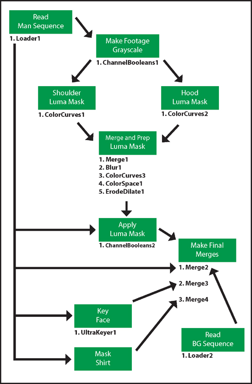
Figure 1.36 Simplified representation of the Fusion node network. Colored boxes represent branches of the network. Specific tools are listed under each branch with low-numbered tools existing farther upstream
Final Chroma Keying Thoughts
When tackling difficult green screen and other chroma key shots, consider the following:
Break It Down Don’t be afraid to tackle different parts of the green screen with different keyers and/or different keyer settings.
Mask and Rotoscope Even if you have ruled out rotoscoping as a replacement for keying, consider masking or rotoscoping problematic areas that do not touch the foreground edge. For example, create a garbage mask to remove unwanted elements from the background or create a positive mask to save areas of the foreground that the keyer is eroding. (A garbage mask is also referred to as a garbage matte.) As long as the masks do not touch the foreground edge, they can be quickly and loosely drawn.
Color Grade Use color effects or tools to subdue spill or adjust the keyed alpha matte.
Pre-Process Adjust the green screen before keying. For example, suppress troublesome noise. You can also color grade the green screen before keying it.
Use Other Keyers Experiment with all the keyers available to a program. They each have their own strengths and weaknesses and may become useful in specific situations.