Chapter 5

Replicating Artifacts
Motion picture film, analog video, and digital video are surprisingly delicate and often pick up damage through their lifespans. This may include scratches, dust, dropout and similar artifacts. Because the artifacts are commonly seen, they are accepted by the viewing public and generally do not diminish the ability to watch the footage. As a compositor, it may be necessary to manually add the artifacts to footage that lacks it to replicate a specific medium. For example, you may need to make digital video appear to be shot on motion picture film that has since aged.
This chapter includes the following critical information:
• Film and video artifact terminology
• Common artifact types and ways to produce them
• Integrating stock footage to gain artifacts
• Generating judder, interlacing, weaving, and halation
• Adding scratches and gate hairs
• Color grading to fade and shift colors
Film and Video Artifact Overview
For the purpose of this book, I will refer to artifacts as unwanted features of a motion picture film or video footage. The artifacts may be inherent to the technology that captures the footage or may be unintended damage.
Grain is a product of the silver halide particles embedded in motion picture film substrates. The grain pattern changes with each frame and is unique to the film stock employed. Film is unique in that the celluloid film strips can pick up scratches, which tend to run vertically. Film is also susceptible to dust spots and dirt. The scratches, dust, and dirt may appear white if they affect the film negative; they may appear black if they affect the positive print. Scratches on positive prints may also appear tinted if they are gouged into the film emulsion. Occasionally, small hairs or other debris appear along the edge of frame after lodging in the film gate during the shoot; these items prevent light from striking the film and appear black. Motion picture film may fade or shift color over time due to a chemical breakdown of the color substrates or bases. Motion picture film can shrink over time or pick up damage to its sprocket holes, causing the film to weave back and forth when projected or digitally scanned.
When motion picture film is transferred to video, frame rate artifacts may occur. For example, pre-digital telecine transfers repeat film frames in order to match the 29.97 fps frame rate of analog SDTV. Motion picture film has a standard frame rate of 24 fps. The repeating of frames appears as judder, which is a series of small hesitations in the motion. Note that stock refers to the physical motion picture film strip. Stock footage refers to a library of previously shot footage that can be licensed for use.
Low-quality lenses and film stock, used in amateur cinematography, are more likely to create halation. Halation appears as fog-like bright spots over bright objects and occurs from light scattering through the lens or the substrates of the film stock.
Noise, as it applies to video artifacts, is a 1-pixel variation in color or luminance created by photons randomly striking a digital sensor or random electrical interference within the camera system. Heavy video noise is generally called static. In terms of video compression, each of the compression schemes creates distinct patterns as the scheme attempts to compress the image into a smaller number of bytes. In particular, footage shot in low light or with inexpensive/inferior equipment is prone to noise and compression degradation. Dropout occurs with both digital and analog video and is the result of missing data. Analog dropout appears as random white dots or undulating bands of static. Digital dropout appears as colored blocks where the original pixel values are missing. Interlacing, as used by SDTV, splits each frame into two fields, with fields broadcast or displayed one at a time. A single field carries every other scanline (horizontal row of pixels). One field carries evenly-numbered scanlines while the other field carries odd-numbered scanlines. Ghosting appears as overlapping copies of the same image when broadcast SDTV is plagued by interference. Although SDTV is no longer used for television broadcast, similar artifacts may be visible with closed-circuit television, low-grade security systems, or other places where archaic video systems are still used.
Artifact Problems and Solutions
When creating film and video artifacts, the main problem is finding or generating those artifacts in a realistic way. Table 5.1 lists common artifacts and methods with which you can create them.
| Artifacts | Method |
| Grain or Noise | Compositing programs generally include an effect or tool that generates noises and/or grain. The effect/tool may generate random1-pixel noise or more complex grain, which tends to be larger than1-pixel. Some effects/tools are capable of generating grain specific to a motion picture film stock or are able to copy noise/ grain from a different piece of footage that carries the artifact. Noise and grain patterns should change with each frame and thus occasionally need additional animation. |
| Static or Dropout | When static covers an entire frame, you can use a noise effect or tool to generate it. When static occurs as dropout and produces undulating bands, it’s best to add it as stock footage. It’s not unusual for large stock footage providers to carry footage of common film and video artifacts for the express purpose of compositing. |
| Ghosting | You can create video ghosting by overlapping multiple copies of the same footage with partial opacity and transform offsets. You can add distortion effects/tools to warp some of the copies to make it appear as if there is additional degradation to the video. |
| Interlacing | Compositing programs almost always include support for interlaced video. The programs can read the interlacing and remove the interlacing by combining the separate fields back into progressive frames. At the same time, there is generally a means to re-interlace fields. Hence, you can add interlacing to footage that never had it. You can also emulate interlacing through matting. For example, to create a single field, create a mask that removes every other scanline. |
| Scratches, Dust, Dirt, or Hair | Much like video dropout, the scratches, dust, dirt, and hair suffered by motion picture film are random and difficult to generate. Although compositing program tools/effects exist that can generate such artifacts procedurally, adding the artifacts as stock footage adds more realism. However, for an isolated artifact, such as a single hair or a single vertical scratch, you can animate a piece of bitmap art or use a paint brush stroke. |
| Weaving | You can emulate the random, side-to-side weaving suffered by old motion picture film by subtly animating the X transform of the footage. To avoid seeing a gap at the frame edges, the footage must be scaled up. |
| Halation | Halation is a form of glow. Glow effects and tools are common in compositing programs. You can create a custom glow by placing a blurred, brightened copy of footage on top of itself. |
| Color Shifting or Color Fading | You can recreate the color shifting or fading suffered by old motion picture film by applying color grading effects or tools. You can also use color grading techniques to emulate the limited color spaces of archaic film or video systems. |
Film Artifact Challenge
Figure 5.1 shows a frame from a high-definition digital video that does not suffer from artifacts (aside from mild video noise). We’ll use various compositing techniques to make this footage appear as if it was shot with motion picture film, suffered damage over time, and was transferred to analog video before a digital copy was made.

Figure 5.1 HDTV video footage of a squirrel does not carry any detrimental artifacts. Image sequence adapted from “in your face Squirrel” by Steve K. and is licensed under Creative Commons Attribution 2.0 Generic (CC By 2.0).
Layer-Based Solution for Film Artifact Challenge
When adjusting footage to emulate motion picture film, you can insert judder and interlacing by mismatching frame rates. You can add grain as an effect, animate weaving, and fabricate hairs and additional scratches in the composite. As a last step, you can color grade all the various elements to create color fading, color shifting, and additional halation.
Adding Judder, Dust, Dirt, and Grain
You can add judder by intentionally mixing different frame rates. While After Effects supplies an effect to add film grain, it’s best to import footage that includes, dust, dirt, and scratches. You can follow these steps:
1. Create a new project. Import the Project-FilesPlatesSquirrelSquirrel.##.png image sequence. Interpret the footage frame rate as 24 fps.
2. Create a new composition that has a resolution of 640×480, a frame rate of 30 fps, and a duration of 48 frames. While the squirrel sequence is 1920×1080 at 30 fps, we are intentionally choosing a lower resolution. This resolution matches SDTV. We–ll pretend that motion picture footage was transferred to SDTV.
3. LMB-drag the image sequence from the Project panel to the composition on the timeline. The footage overhangs because of its larger size. Change the new layer’s Scale to 48%. Interactively move the layer to improve the composition. For example, center the squirrel (Figure 5.2).

Figure 5.2 The squirrel layer is scaled down and repositioned within the smaller composition.
4. Note that the image sequence extends beyond the end of the timeline. This is due to a mismatch between the frame rate interpretation of the image sequence (24 fps) and the frame rate of the composition (30 fps). When there is such a mismatch, After Effects repeats frames of the layer so that a 24 fps becomes 30 fps. Play back the timeline. The repeating of frames leads to a judder, where the motion is no longer as smooth as the original footage. You can identify the repeat frames by playing forward one frame at a time. For example, frame 0 is repeated to form a new frame 1, frame 5 is repeated to form a new frame 6, and so on. Normally, judder is undesirable. However, we can intentionally add it to emulate the telecine process, where motion picture film was transferred to SDTV analog video.
5. The quickest and most effective way to add scratches, dust, and dirt to footage is to combine it with a copy of the real artifacts. As mentioned, stock footage providers often carry motion picture footage with artifacts gained from real-world use. The most useful footage is an empty, white background so the artifacts can be clearly seen. Import the Project-FilesPlatesArtifactsArtifacts.##.png image sequence. Interpret the footage frame rate as 24 fps. This footage was derived from a telecine transfer of motion picture leader (Figure 5.3). (A leader is a piece of film at the start of a film reel that includes a countdown.)

Figure 5.3 A frame from the Artifacts stock footage, which includes dust and dirt spots, small vertical scratches, and discoloration.
6. LMB-drag the artifact sequence from the Project panel to the top of the later outline. Change the layer’s Scale to 105% to cut off the black bar at the bottom. Initially, the footage obscures the squirrel. Change the Blending Mode menu for the top layer to Multiply. The darkest areas of the artifacts are placed over the squirrel, while the bright areas of the artifact footage is ignored. The yellow discoloration of the artifact layer also affects the overall color balance. If you do not see the Blending Mode menu, click the Toggle Switches / Modes button at the bottom of the layer outline.
7. Grain is an inherent part of motion picture film. The grain patterns, sizes, and colors varied with each film stock used to shoot the footage, plus the positive film stock used to make prints. Smaller gauge formats, such as 16 mm or 8 mm, generally included heavier grains. Create a new composition that matches the resolution, frame rate, and duration of the first one. Rename the first composition Dirt. Name the new composition Grain. Nest the Dirt composition within the Grain composition. Select the nested layer and choose Effect > Noise & Grain > Add Grain. Set the Grain effect’s Viewing Mode menu to Final Output. Change the Preset menu to a film stock type (each one creates a different grain pattern). Expand the Tweaking section, and experiment with the Intensity and Size values. For example, set the Preset menu to Eastman Color Neg 100T (5254), Intensity to 1.5, and Size to 1.5. Play back. An animated noise is added, affecting the color and quality of the footage (Figure 5.4).

Figure 5.4 Dust, dirt, scratches, discoloration, and heavy grain is added.
Interlacing
For this project, we are emulating motion picture footage that was transferred to analog video before a digital copy was made. As such, we can introduce interlacing. You can follow these steps:
1. Create a new composition that has a resolution of 1920×1080, a duration of 96, and a frame rate of 29.97. Name the new composition Interlace. When the program uses a standardized frame rate with a decimal place, like 23.976, 29.97, or 59.94, it understands that interlacing is present. Although the interlacing is not visible at this point, it’s possible to render out the composition with interlaced fields.
2. LMB-drag the squirrel sequence from the Project panel into the Interlace composition. The sequence, at 48 frames, is half the length of the composition. With the sequence layer selected, choose Layer > Time > Time Stretch. In the Time Stretch window, set Stretch Factor to 200%. Click the OK button to close the window. This doubles the length of the sequence by repeating frames. We will use the extra frames to split each frame into two fields when it’s time to render. With the sequence layer selected, choose Layer > Frame Blending > Pixel Motion. This fabricates, new in-between frames by examining existing frames instead of simply repeating frames. (Pixel Motion uses optical flow technique to track patterns with the layer over time.) In this way, the rendered fields will not appear identical. One trait of interlaced SDTV is the fact that the upper and lower fields sometimes appear mismatched, particularly when an object is moving quickly.
3. With the Interlace composition selected, choose Composition > Add To Render Queue. Switch to the Render Queue tab on the timeline. Click the link next to Output Module. Change the Format menu to PNG Sequence. Click OK to close the window. Click the link next to Output To. Select a name and location for the PNG image sequence. For example, enter Interlaced.[##].png into the File Name field. Click Save to close the window. Click the link next to Render Settings. Change the Field Render menu to Upper Field First. This forces the program to render fields and not render progressive frames. Click the Render button.
4. When the Interlaced sequence has rendered, choose File > Import > File to import the new image sequence. An example sequence is included with the tutorial files as Project-FilesPlatesInterlacedInterlaced.##.png. RMB-click over the sequence name in the Project panel and choose Interpret Footage > Main. In the Interpret Footage window, select the Assume This Frame Rate radio button and enter 59.94 into the matching field. This speeds up the sequence, returning it to its original length. In addition, the 59.94 tells the program to interpret the footage as interlaced. Double-click the sequence name to open it in the Footage view. The Footage view displays individual fields if you step forward using the keyboard’s Page Up and Page Down button. Each button click moves one field or a half-frame. If you zoom into the view, you can see the interlaced combing (the mismatching of every other scanline) on fields where the squirrel is moving rapidly (Figure 5.5).
5. Switch back to the Composition view and the Dirt composition tab. Turn off the Video eye switch to hide the lower squirrel layer. LMB-drag the new, interlaced image sequence into the Dirt composition. Change the new layer’s Scale and Position values to match the same properties of the hidden layer. Initially, the composition ignores the interlacing. Choose Composition > Composition Settings. Change the Frame Rate to 29.97 and close the window. The interlacing becomes visible. However, the combing created by the fields is not sharply defined. Nevertheless, you can see a ghosted overlap when the motion is at its greatest (Figure 5.6). The interlacing emulation is complete.

Figure 5.5 Interlaced combing seen on frame 11 when examining interlaced image sequence in the Footage view. The combing is most visible when there is rapid movement.

Figure 5.6 When the interlaced sequence is placed in the Dirt composition, and the composition is given a frame rate of 29.97, the interlacing is visible as ghosting.
Adding Film Weave and Lone Hairs and Scratches
We can add film weave, the random side-to-side motion of the frame, with simple animation. To add hairs or scratches that are missing from the artifact footage, we can turn to the program’s built-in Brush tool, solid layers, and distortion effects. Follow these steps:
1. Return to the Dirt composition. At this point, the footage has gained interlacing, judder, dust, dirt, and some discoloration. Change the Parent menu of the top, artifact layer to layer 3. This forces the top layer to follow the lowest layer, which is the interlaced render.
2. Go to the first frame. Expand the Transform section of the lowest layer. Click the Time icon beside Position. A keyframe is set. Move a few frames forward and interactively move the layer a few pixels to the left. Move a few frames forward and interactively move the frame a few pixels to the right. Repeat this process to create a random left/right motion through the remainder of the timeline. To save time, you can repeat groups of keyframes by dragging a selection marquee around several keyframes, pressing Ctrl/Cmd+C to copy, moving the time slider forward, and pressing Ctrl/Cmd+V to paste the copied keyframes. Play back. The frame weaves back and forth as if the film strip is meandering in a projector or a scanner.
3. To create a hair, as if the hair was caught in the film gate as the footage was shot, we can create stroke with the Brush tool. Double-click the top artifact layer to open the footage in the Layer view. Go to the first frame of the timeline. Click the Brush tool icon in the toolbar. In the Brushes panel, change the Diameter to 2. In the Paint panel, change the brush color to black. LMB-drag a stroke in the Layer view from the frame edge to replicate a curled hair (Figure 5.7). Return to the Composition view. Expand the Paint > Brush 1 > Stroke Options of the top layer. Reduce the opacity value in the Stroke Options subsection to 50% to fade the hair slightly. Extend the duration bar of the stroke so it lasts the entire timeline. Optionally, you can adjust the Scale or animate the Position or Rotation value in the Paint > Brush 1 > Transform subsection. Real-life gate hair often change position, suddenly appear, or suddenly disappear due to the vibrations of the camera mechanism.

Figure 5.7 Close-up of hair drawn with the Brush tool.
4. To create a vertical scratch, we can animate a solid layer. Choose Layer > New > Solid. In the Solid Settings window, change the Width to 6 and Height to 500. Set the color to dark blue. Name the solid Scratch and click OK to close the window. The new solid is added to the top of the layer outline. Interactively move the solid left or right to select its initial position. To blend the scratch with the footage, change the solid layer’s Blending Mode menu to Diference. This tints the scratch based on the colors of lower layers (Figure 5.8). Optionally, you can select different blending modes to create different color combinations. For example, setting the Blending Mode to Multiply creates a darker, more uniform scratch. Adjust the Opacity to lighten or darken the scratch. Go to the first frame. Randomly animate the solid layer’s Position so that the scratch slowly drifts left or right.

Figure 5.8 A vertical scratch is created by adding a thin solid layer. The Blending Mode menu for the layer is set to Difference. Distortions to the scratch are added with a Wave Warp effect.
5. At this point the scratch does not change shape while real-world scratches often wiggle or suddenly start and stop. To emulate this change we can add a distortion effect. With the solid layer selected, choose Effect > Distort > Wave Warp. The effect adds sine-based distortion. Set the effect’s Wave Height and Wave Width to 100. Set the Wave Speed to 5. Set the Antialiasing menu to High. Randomly animate the Direction property changing from 90 to values slightly higher or lower. Values about 90 leave the scratch as a straight line. Values higher or lower break the scratch into small, tapered segments. Play back. The portion of the composite is complete.
Color Fading
We can replicate the color fading, color shifting, and halation that affects degraded film stock by adding color grading effects. You can follow these steps:
1. At this stage, the grain is added in the Grain composition, which means that the grain is applied after the weave is animated in the Dirt composition. A better solution would be to add the grain to the layer that has the weave. To do this, select the Add Grain effect in the layer outline of the Grain composition. Press Ctrl/Cmd+X to cut the effect off of the layer. Return to the Dirt composition. Select the lowest, interlaced sequence layer. Press Ctrl/Cmd+V to paste the grain effect onto this layer. For clarity, return to the Grain composition and rename it Color. We will add color grading to this composition.
2. With the sole layer selected, choose Effect > Color Correction > Color Balance, Effect > Color Correction > Hue/Saturation, and Effect > Blur & Sharpen > Channel Blur. Increase the value of the Color Balance effect’s Shadow Red Balance, Midtone Red Balance, and Highlight Red Balance. This shifts the footage from green to red. Some modern film stocks, if not properly handled, become redder with age. Reduce the Master Saturation of the Hue/Saturation effect to fade out the colors. Increase the Red Blurriness value of the Channel Blur effect to emulate halation. Halation sometimes occurs with motion picture stock when light scatters through a particular color substrate (film stock uses yellow, cyan, and magenta). You have a great deal of flexibility when color grading—feel free to experiment with effect property values. Play back. The composite is complete.
Figure 5.10 shows two frames from the final composite. A chart detailing the layer workflow is illustrated by Figure 5.9. The project is included with the tutorial files as Project-FilesaeFilesChapter5FilmArtifactChallengeFinal.aep.

Figure 5.9 Compositions, layers, and effects used in After Effects. Compositions are shown as purple boxes. Layers are numbered and written in bold type. Effects are listed beside each layer. The arrow indicates nesting.

Figure 5.10 Frame 19 (top) and frame 44 (bottom) from final composite. Grain, dust, dirt, scratches, interlacing, film weave, color fading, color shifting, halation, and a gate hair are added. Compare this to Figure 5.1 earlier in this chapter.
Node-Based Solution for Film Artifact Challenge
When adjusting footage to emulate motion picture film, you can add interlacing and grain with specialized tools. You can add dust, dirt, and scratches by importing stock footage. You can fabricate hairs and additional scratches in the composite. As a last step, you can color grade all the various elements to create color fading, color shifting, and additional halation.
Interlacing
We can generate an interlaced version of our progressive footage inside Fusion by rendering the output of a Fields tool. You can follow these steps:
1. Create a new project. Choose Edit > Preferences and set the resolution to 1920×1080 and the frame rate to 29.97 fps. 29.97 fps is the frame rate of interlaced SDTV. Import the Proj-ect-FilesPlatesSquirrelSquirrel.##.png image sequence. Set the Global End Time to 47.
2. Create a Time Speed tool (Tools > Miscellaneous > Time Speed). Connect the output of the Loader tool to the input of the Time Speed tool. Set the tool’s Speed property to 0.5. Connect the Time Speed Tool to a Display view. This slows the image sequence, causing it to last from frames 0 to 95. This is necessary to render interlaced fields. Set the Global End Time to 95. Play back the timeline to see how the footage has been lengthened. Create a Fields tool (Tools > Miscellaneous > Fields). Connect the output of the Time Speed tool to the input of the Fields tool. See Figure 5.16 as reference for the final tool networks. Set the Field tool’s Operation menu to Interlace. Each whole frame is converted to a field. Each pair of fields is combined into a single new frame. No scanlines are lost; thus, the height of the frame is doubled. You can see scanline combing if you zoom into the Display view while the HiQ button is activated (Figure 5.11). The sequence returns to its original length of 48 frames. Set the Global End Time back to 47.

Figure 5.11 Scanline combing created by the Fields tool. Note the doubling of the frame height.
3. To make the interlaced version useful for other parts of the composition, we’ll render it to disk. To do so, connect a Saver tool (Tools > I/O > Saver) to the Fields tool. When you add a Saver tool, the Save File window opens. Navigate to a folder where you’d like to render the new sequence. Choose a name and a file type through the name field. For example, enter Interlaced2.00.png. Click the Save button to close the window. When you are ready to render, click the Render button under the time ruler. The Render Settings window opens and is set to the highest render quality by default. Click the Start Render button.
4. When the render is finished, create a new Loader and import the rendered, interlaced image sequence. An example sequence is included with the tutorial files as Project-FilesPlatesInterlaced2Interlaced2.##.png. Create a Resize tool (Tools > Transform > Transform) and connect it to the output of the new Loader. Connect the Resize tool to a Display view. Set the tool’s height to 1080. The footage regains its proper height. The interlace combing disappears. However, the ghosting that occurs when the squirrel moves rapidly remains (Figure 5.12).

Figure 5.12 The interlace ghosting remains after the proper height is returned to the footage.
5. The final output of the composition will be 640×480. Hence, we need to scale down the output even further and crop it into a new aspect ratio. Create a Scale and Crop tool. Connect the output of the Resize tool to the input of the Scale tool. See Figure 5.16 later in this chapter as reference for the final tool networks. Connect the output of the Scale tool to the Crop tool. Connect the Crop tool to a Display view. Set the Crop tool’s X Size to 640 and Y Size to 480. To better frame the squirrel, go back to the Scale tool and reduce the Size to 0.6. Go back to the Crop tool and adjust the X Offset and Y Offset to center the squirrel. This part of the composite is complete.
Adding Dust, Dirt, Grain, and Weaving
While Fusion supplies an effect to add film grain, it’s best to import footage that includes, dust, dirt, and scratches. You can follow these steps:
6. Create a new Loader and import the Project-FilesPlatesArtifactsArtifacts.##.png image sequence. Create a Merge tool. Connect the output of the new Loader to the Foreground of the Merge tool. Connect the output of the Crop tool to the Background of the Merge tool. Connect the Merge tool to a Display view. Set the Merge tool’s Apply Mode to Multiply. The dust, dirt, and scratches of the artifact sequence appear over the squirrel footage (Figure 5.13).
7. Select the Merge tool and choose Tools > Film > Film Grain. A Film Grain tool is connected automatically. Connect the new tool to a Display view. Deselect the Film Grain tool’s Monochrome checkbox. Color grain appears and is automatically animated. Raise the tool’s Master Size slider to 1.5 to scale up the grain.

Figure 5.13 Close-up of dust, dirt, and grain.
8. To add film weave, where the frame drifts left and right, we will need to animate the frame position before the Crop tool. Place your mouse over the connection line near the output of the Scale tool. RMB-click and choose Add Tool > Transform > Transform. A new Transform tool is inserted between the Scale and Crop tools. See Figure 5.16 later in this chapter as reference for the final tool networks. Go to frame 0. Select the Transform tool. RMB-click over the Center property name and choose Animate. Move forward a few frames and interactively move the frame a few pixels to the left. Move forward a few frames and interactively move the frame a few pixels to the right. Continue this process until the end of the time ruler, creating a random left/right motion. Play back. The frame weaves back and forth. This section of the composite is complete.
Adding Lone Hairs and Scratches
To add hairs or scratches that are missing from the artifact footage, we can turn to the program’s built-in Paint, Background, and Lens Distort tools. Follow these steps:
1. Select the Loader3 tool (the one that imports the artifact image sequence). Choose Tools > Paint > Paint. A Paint tool is inserted between the Loader3 and Merge1 tools. Connect the Paint tool to a Display view. Click the Stroke sub-tool in the Paint toolbar. In the Brush Controls section, set the Size to 0.005. Set the brush color to black. In the Display view, LMB-drag to draw a short, curly hair at the bottom-right side of the frame. Go to the Modifiers tab. Expand Stroke1. Expand the Stroke Controls subsection. Make sure the Stroke Animation menu is set to All Frames. When Stroke1 is selected, its transform handle is visible in the Display view. Optionally, you can animate the stroke’s Center and Angle to make it look like the hair is jittering. The stroke’s transform properties are located in the Stroke Controls section. You can reduce the Opacity value, in the Color subsection, to make the hair appear softer.
2. To add a long, vertical scratch that lasts the duration of the time ruler, we can use a solid-colored background. Create a new Merge tool. Choose Tools > Creator > Background and Tools > Warp > Lens Distort. Select the Background tool and set its color to black. In the Tools > Image tab, set its Width property to 5. Set its Height property to 500. Connect the output of the Background to the input of the Lens Distort tool. Connect the output of the Len Distort tool to the Foreground of Merge2. Break the connection between Merge1 and Film Grain. Connect the output of Merge1 to the Background of Merge2. Connect the output of Merge2 to the input of Film Grain. Connect Merge2 to a Display view. The thin solid, created by the Background tool, appears over the squirrel (Figure 5.14). Select the Merge2 tool. Use the transform handle to interactively position the scratch. Go to frame 0. RMB-click over the Center property name and choose Animate. Proceed to randomly move the scratch over time so that it drifts left and right. Reduce the Blend slider to reduce the scratch opacity. Optionally, animate the Blend value increasing and decreasing over time so that the scratch fades in and out. At this stage, the scratch is perfectly straight. To bend the scratch, we can apply a distortion tool. Select the LensDistort1 tool. RMB-click over the Distortion property name and choose Animate. Proceed to randomly increase and decrease the value over time so that the scratch bows back and forth. Only slight value changes are necessary. This part of the composite is complete.

Figure 5.14 Close-up of vertical scratch added with a Background tool, as seen on the last frame.
Color Fading
We can replicate the color fading, color shifting, and halation that affects degraded film stock by adding color grading tools. You can follow these steps:
1. Select the FilmGrain1 tool and choose Tools > Blur > Blur. A Blur tool is connected. Select the new Blur tool and choose Tools > Color > Color Corrector. See Figure 5.16 later in this chapter as reference for the final tool networks. Connect the new Color Corrector to a Display view. Select the Blur tool. Deselect the tool’s Green, Blue, and Alpha checkboxes. Increase the Blur Size to 35. This blurs the red channel by itself, replicating halation. Select the Color Corrector. Reduce the Master – Saturation slider. LMB-drag the center handle to the color wheel towards the red area, thus tinting the footage and making it appear as it has faded and shifted towards red (Figure 5.15).

Figure 5.15 The final composite, as seen on frame 20.
Play back. The composite is complete. Note that if you choose to render the result through a Saver tool as an image sequence, the output will be progressive, whole frames, despite the project frame rate of 29.97.
The final tool network is illustrated by Figure 5.16. A chart detailing the node workflow is illustrated by Figure 5.17. The project is included with the tutorial files as Project-FilescompFilesChapter5FilmArtifactChallengeFinal.comp.
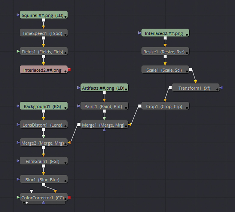
Figure 5.16 The final tool networks.
Final Artifact Replication Thoughts
Because film and video artifacts have a tendency to be randomly gained through age or damage, it’s a good idea to incorporate stock footage that includes these artifacts in the composite whenever possible. Stock footage that includes film dust, dirt, scratches, and discoloration is fairly common. The same holds true for footage that includes video static and dropout. To generate artifacts that are fairly simple, such as an isolated hair or scratch, interlacing, or film weave, you can generally use the compositing program’s built-in effects, tools, or functions.

Figure 5.17 Simplified representation of the Fusion node network. Colored boxes represent branches of the network. Specific tools are listed under each branch with low-numbered tools existing farther upstream.
When replicating artifacts, consider the following:
Think outside the Box Even if your compositing program fails to carry an effect, tool, or plug-in that creates a very specific artifact, there is often a way to tweak more mundane effects or tools to produce what you want. Hence, it pays to experiment. Also, consider chaining multiple effects and tools together to come up with more complex results.
Color Grade to Add Realism Every film and video medium uses unique color space. The colors of every analog medium changes as it ages. Hence, 35mm Cinemscope appears different from Super-8, which appears different from VHS, BetaCam, and so on. It pays to be familiar with the different looks of film and video throughout recent history. Even digital video will have color space variations between different digital cameras and different outputs, such as television or theater projection.