
| 8 | Sensors and Camera |
Chapter Objectives
In this chapter you will:
Understand Motion Sensors, Environmental Sensors, and Positional Sensors.
Learn how to acquire measurement data from a sensor.
Explore the SensorEvent class and SensorEventListener interface.
Create applications using the accelerometer.
Learn to utilize the built-in camera application.
■ 8.1 Sensors and Mobile Devices
Android devices come with a varied set of embedded sensors; collectively, these sensors enable the creation of applications across a wide range of domains, such as gaming, healthcare, social networks, safety, environmental monitoring, and transportation. A sensor is simply a device that measures a physical quantity (e.g., the tilt of a device, or sudden movement) and converts it into a signal that an application can interpret. Android users typically experience sensors by means of touchscreens, accelerometers, gyroscopes, cameras, and GPS. For example, an accelerometer often enhances a camera-based application by helping to determine whether the user is holding the device in a landscape or portrait view. The application can then use that information to automatically reorient the display or correctly orient captured photos on the device during viewing.
Sensors allow incorporation of different input methods to improve user interface design and application functionality. Android application developers should consider alternative forms of user input when designing an application. It is particularly useful to explore opportunities in adaptability and the formation of new kinds of user interfaces during the design phase. For example, users of gaming apps may benefit from gesture-based control, such as tilting the device as an input method. Gesture-based game applications can provide challenging and engaging experiences, with increasing levels of skill required related to mastery of the sensor-software interface.
For individuals with physical limitations, being able to control a mobile device with the flick of a wrist or a simple turning motion can provide enhanced access to app features, such as editing or typing text, that would otherwise not be available. Innovations in gesture control are particularly appropriate for applications designed for use on wearable devices. For example, a user with disabilities could rely on sensors to navigate through onscreen icons by a simple turn of the head.
■ 8.2 Android Sensors
Most Android devices have multiple built-in sensors. These sensors supply raw data from three general categories: motion, environmental conditions, and the orientation of the device. Measurements are often provided with a relatively high degree of precision and accuracy, making them useful for monitoring device movement and positioning within three dimensions and also changes in the ambient environment near a device.
8.2.1 Motion Sensors
Users generate motion events when they move, shake, or tilt a device. An application can interpret motion in two basic ways: (1) Movement can be the result of direct user input, such as the user tilting the device to steer a moving object in a game, and (2) motion can also be detected as feedback from the physical environment, such as a device being present in a car that is moving. Hardware sensors, such as accelerometers and gyroscopes, detect motion events. Although accelerometers and gyroscopes are similar in purpose, they measure different things.
The general purpose of an accelerometer is to measure the force of acceleration, whether gravity or movement has caused the acceleration. The accelerometer is commonplace in existing applications for detecting a device’s orientation. Because gravity is applying a constant acceleration toward the Earth, the Android platform can determine which way is down, based on the accelerometer. Figure 8-1 illustrates changes in orientation of a stationary device. Android’s built-in three-axis accelerometer is often used to manage context-aware elements in an application, such as controlling game interfaces, performing power management, shuffling music, performing “undo” actions, and enabling pedometers.
The gyroscope measures the rate of rotation around three axes. Also called angular rate sensors, gyroscopes measure how quickly an object rotates, allowing a device to measure and maintain orientation. Gyroscopic sensors can monitor device positions, orientation, direction, angular motion, and rotation. When applied to an application, a gyroscopic sensor commonly performs gesture-recognition functions.
Gyroscopes are the only inertial sensors that provide accurate, latency-free measurement of rotations without being affected by external forces, including magnetic, gravitational, or other environmental factors. Figure 8-2 illustrates how the rotations, which are measured in radians, behave along the three axes: x (pitch), y (roll), and z (yaw). Pitch, roll, and yaw motions are transformations from world to body frame with motions performed relative to body-frame axes. Yaw, the rotation angle around the world-frame z-axis, is required to determine whether the device is facing north, south, east, or west. It takes values between π and –π, with 0 representing north and π/2 representing east. Pitch, the rotation angle around the world-frame x-axis, can be used to determine whether the device is facing up or down. Pitch values can range between π/2 and –π/2. When the device is facing up, the pitch value is zero; when the device is facing down, the pitch value is π/2.


The accelerometer and gyroscope are designed to return multidimensional arrays of sensor values for a given motion event. For example, when a device registers a motion event, the accelerometer produces three motion readings, one for each axis: x, y, and z. Each motion reading measures changes in velocity over time along a linear path. This means that when a device is tilted upwards, it is being pitched with the top edge rising above the bottom edge, so the sensor reads a negative y value. Rolling the device to the right, so the left side comes up, produces a reading that shows positive x values.
The gyroscope will return rate-of-rotation data for the three coordinate axes. When combined into a single device, the accelerator and gyroscope can create a powerful array of information. In addition, software-based sensors, such as gravity, linear acceleration, and rotation sensors, can derive their data from the accelerometer and gyroscope.
8.2.2 Environmental Sensors
Android devices may contain a range of environmental sensors that make the device aware of the world around it. Environmental sensors measure specific environmental parameters, such as ambient air temperature and pressure, illumination, and humidity. It should be noted that very few devices have dedicated ambient temperature sensors. An application can compute the temperature based on the temperature of the device’s internal electronics or battery, which is similar to the ambient temperature of a device that has been on standby. Most often, an application uses a weather service content provider to supply ambient temperature.
Environmental sensors are hardware-based and are available only if a device manufacturer has built them into a device. With the exception of the light sensor, which most device manufacturers use to control screen brightness, environment sensors are not always available on devices.
The raw data provided by light, pressure, and temperature sensors usually require no calibration, filtering, or modification. These sensors can also be used alongside each other.
For example, dew point is the temperature at which a given volume of air must be cooled, at constant barometric pressure, for water vapor to condense into water. Data from a device’s humidity sensor and temperature sensor can be used in tandem to compute dew point.
The camera is also classified as an environmental sensor. The camera can be used for many applications beyond just taking photographs. Consider the measurement of heart rate. An application can instruct the user to place the tip of an index finger on the device’s built-in camera, which can then be used to track color changes in the fingertip. The captured color changes, linked directly to the user’s pulse, can be displayed as a real-time chart illustrating the user’s heartbeat.
8.2.3 Positional Sensors
A magnetometer, such as a geomagnetic field sensor, is built into most Android devices. This type of sensor is used to determine the position of a device. A proximity sensor, also prevalent in devices, is used to determine how close an object is to the device, specifically to the face of the device. Proximity data are particularly important when creating applications that must determine when a device is being held close to a user’s face, such as during a phone call.
Positional sensors are useful for determining a device’s physical position in the world’s frame of reference, such as computing the device’s position relative to the magnetic North Pole. These sensors are often used in tandem with motion sensors. For example, the geomagnetic field sensor can be used in combination with the accelerometer to determine a device’s horizontal compass reading. Positional sensors are not typically used to monitor device movement or motion, such as shake, tilt, or thrust.
■ 8.3 Working with Sensors
In addition to the sensors mentioned previously, Android also relies on software-based sensors. Software-based sensors imitate hardware-based sensors by deriving their data from one or more of the embedded physical sensors. For example, linear acceleration measures acceleration along a single axis. This software-based sensor requires raw data derived from the accelerometer.
Few Android-powered devices have every type of sensor. Most devices include an accelerometer and a magnetometer, but fewer devices have barometers or thermometers. It is also not uncommon for a device to have more than one sensor of a given type, such as the inclusion of two gravity sensors, each one with a different range. Table 8-1 summarizes a set of common sensors that are supported by the Android platform. The getSensorList() method lists all of the available sensors in a particular device.
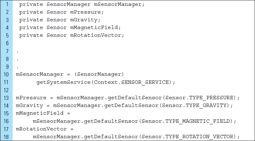
To acquire measurement data from a sensor, a SensorManager object is required. Once instantiated, this object can be used to specify an instance of a physical sensor. Consider the following segment of code. The object mSensorManager is used to access both hardware-based and software-based sensors.
Lines 2–5: |
The |
Lines 10–11: |
|
Lines 13–18: |
The
|
Sensor |
Identifier Name and Description |
Accelerometer |
Measures the acceleration force in m/s2 that is applied to a device on all three physical axes (x, y, and z), including the force of gravity. Useful for motion detection, such as shaking and tilting. |
Ambient temperature |
Measures the ambient room temperature in degrees Celcius. Commonly used for monitoring air temperatures. |
Gravity |
Measures the force of gravity in m/s2 that is applied to a device on all three physical axes (x, y, and z). This sensor is similar to an accelerometer. However, unlike an accelerometer, which is a hardware sensor, the gravity sensor can be software- or hardware-based. |
Gyroscope |
Measures a device’s rate of rotation in rad/s around each of the three physical axes. This hardware sensor detects rotation, such as spinning and turning. |
Light |
Measures the ambient light level and is used to control screen brightness. |
Linear acceleration |
Measures the acceleration force in m/s2 that is applied to a device. This sensor can be used to monitor acceleration along a single axis. |
Magnetic field |
Measures the ambient geomagnetic field and is required for creating applications that need a compass. |
Pressure |
Measures the ambient air pressure and is useful in monitoring air pressure changes. |
Proximity |
Measures the proximity of an object relative to the device. This sensor is often used to determine the position of a person’s ear to a mobile phone during a call. |
Relative humidity |
Measures the relative ambient humidity (in percent). |
Rotation vector |
Measures the orientation of a device using a rotation vector. |
Step detector |
The step detector analyzes accelerometer input to recognize when the user has taken a step. An event can be triggered with each step. |
Step counter |
The step counter tracks the number of steps taken by the user. An event is triggered with each change in the step count. |
The SensorManager class provides various methods for accessing and listing sensors. It is also used for registering and unregistering sensor event listeners.
The SensorEvent class is used by the system to create a sensor event object, which provides information about a sensor event. The SensorEventListener interface uses two callback methods that receive notifications (sensor events) when sensor values change or when sensor accuracy changes. A SensorEvent object includes the following information:
Raw sensor data
Type of sensor that generated the event
Accuracy of the data
Time-stamp for the event
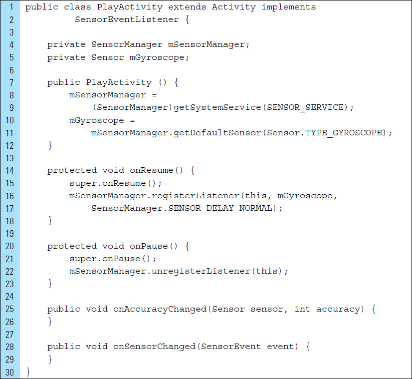
In the segment of code shown below, PlayActivity is an Activity that implements a SensorEventListener interface. A SensorManager object is used to access the gyroscope sensor. A listener event for the gyroscope sensor is registered in the activity’s onResume() callback. It is unregistered in the onPause() callback. It is considered good practice to unregister sensor listeners when they are no longer needed.
Two abstract methods are implemented in SensorEventListener: on-AccuracyChanged() and onSensorChanged(). If the gyroscope’s accuracy changes, the onAccuracyChanged() method will be called. If the gyroscope reports a new value, the onSensorChanged() method will be called. The onSensorChanged() callback method typically handles incoming sensor data.
Not all sensors are present in every device. It is considered good practice to verify the existence of a sensor before attempting to use it. To identify the sensors that are on a device, a SensorManager object is first used to reference the sensor service. getSensorList() can then be called by that object to return a list of sensors on a device. In the code segment below, the constant TYPE_ALL is used to specify every sensor on the device.

To determine the existence of a specific type of sensor, the method getDefaultSensor() can be called for verification. In the code segment below, getDefaultSensor() is passed the type constant for the gyroscope sensor. If a device has more than one sensor of a given type, one of the sensors must be designated as the default sensor. If a default sensor does not exist for a given type of sensor, the method call returns null, which means the device does not have that type of sensor.

Android device manufacturers have flexibility in how they construct their mobile devices. No specific requirements exist for the configuration of sensors in an Android-powered device; this means that attributes and capabilities of sensors are not uniform across all devices. The ability to determine sensor characteristics is often useful for an application, which may require different behavior based on sensor capabilities.
The code segment below uses method calls to get specific information about an existing sensor; for example, getPower() can be used to obtain the sensor’s power requirements. getMaxumumRange() can determine a sensor’s resolution and maximum range of measurement. The getMinDelay() method, called on Line 9, is useful for obtaining the rate at which a sensor can acquire raw data. The method will return an integer value representing the minimum time interval (in microseconds) the sensor can use to sense data. A sensor that returns a nonzero value for the getMinDelay() method is a streaming sensor. Streaming sensors can sense data at regular intervals. A nonstreaming sensor reports data only when there is a change in the parameters it is sensing.
Additional method calls, such as those found on Lines 11 and 12, can be used to determine a version number or whether a particular vendor has supplied the embedded sensor.


■ 8.4 Coordinate System
The coordinate system of an Android device is defined relative to the screen of the device in its default orientation. For example, the default mode of an Android mobile phone is typically the portrait orientation. As shown in Figure 8-3, the x-axis runs in the direction of the short side of the screen. The y-axis runs in the direction of the long side of the screen, and the z-axis points out of the screen.

The natural orientation for many tablet devices is landscape, rather than portrait mode. It is important that an application does not assume that a device’s default orientation will always be portrait. Consider an accelerometer on an Android phone with a default portrait orientation. In this system, coordinates behind the screen have negative z-axis values. These axes for the device will not be swapped when the device’s screen orientation changes. The sensor’s coordinate system will not change as the device moves.
The coordinate system of the world, the inertial frame of reference, defines the x-axis as the cross-product of the y-axis with the z-axis. The y-axis is tangential to the ground and points toward the North Pole. The z-axis points perpendicular to the ground toward the sky.
These two coordinate systems are aligned when the mobile phone is sitting perfectly flat on a table with the screen facing up and pointing north. In this orientation, the accelerometer, which measures acceleration in meters/seconds2 for each axis, will produce the results: 0, 0, 9.8. These values are the acceleration measurements applied to the phone minus the force of gravity. The force of gravity is 9.8 meters/seconds2, defined by the constant SensorManager.GRAVITY_EARTH.
values[0]: Acceleration minus the force of gravity on the x-axis
values[1]: Acceleration minus the force of gravity on the y-axis
values[2]: Acceleration minus the force of gravity on the z-axis
This means that when the device lies flat on a table and is pushed on its left side toward the right, the x acceleration value is positive. When the device lies flat on a table, the acceleration value is +9.8, which corresponds to the acceleration of the device (0 m/s2) minus the force of gravity (-9.8 m/s2).
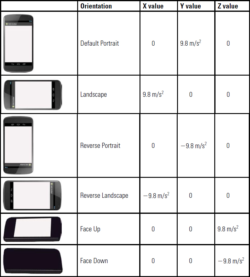
When the device lies flat on a table, face-up, with an acceleration of (A m/s2), the acceleration value is equal to (A+9.8) which corresponds to the acceleration of the device (+A m/s2) minus the force of gravity (-9.8 m/s2). Table 8-2 shows the axes values read from the sensor corresponding to several positions of the device.
TABLE 8-2 Accelerator axes readings
■ Lab Example 8-1: Experiment with Tilt Input: Roaming Ball
The market for mobile gaming often dominates other gaming platforms. As different control interfaces emerge, mobile game developers can consider multiple input options, including tilt as an input method. Tilt-detection is as simple as detecting which accelerometer axis is experiencing the most force from gravity. This lab example explores the use of the accelerometer to move a ball around the screen. More specifically, it illustrates how rotations, along the axes of the device, can be detected and used to control onscreen action. Accelerometer-based tilt input is supported on a variety of mobile games and is frequently used as a means of user input, most notably used in apps where tilting and rotating the device can control game play.
It should be noted that it is not possible to test sensor code on an emulator because an Android virtual device cannot emulate sensors. This lab example, as well as the remaining lab examples in this chapter, must be tested on a physical device.
Part 1: The Design
When the application first launches, the user is presented with a ball positioned at a specific x, y location on the screen. Three text fields are used to display the x-, y-, and z-axis readings from the accelerometer. As the user tilts and rotates the device, the text fields are updated to show the current accelerometer readings. In addition, the ball moves in accordance with the tilt and roll of the device, as shown in Figure 8-4. The ball is not allowed to roll offscreen, and it is constrained by the virtual boundaries of the screen.

Part 2: Application Structure and Setup
The settings for the application are as follows:
Application Name: |
Roaming Ball |
Project Name: |
RoamingBall |
Package Name: |
|
Android Form: |
Phone and Tablet |
Minimum SDK: |
API 18: Android 4.3 (Jelly Bean) |
Target SDK: |
API 21: Android 5.0 (Lollipop) |
Compile with: |
API 21: Android 5.0 (Lollipop) |
Activity Name: |
|
Layout Name: |
|

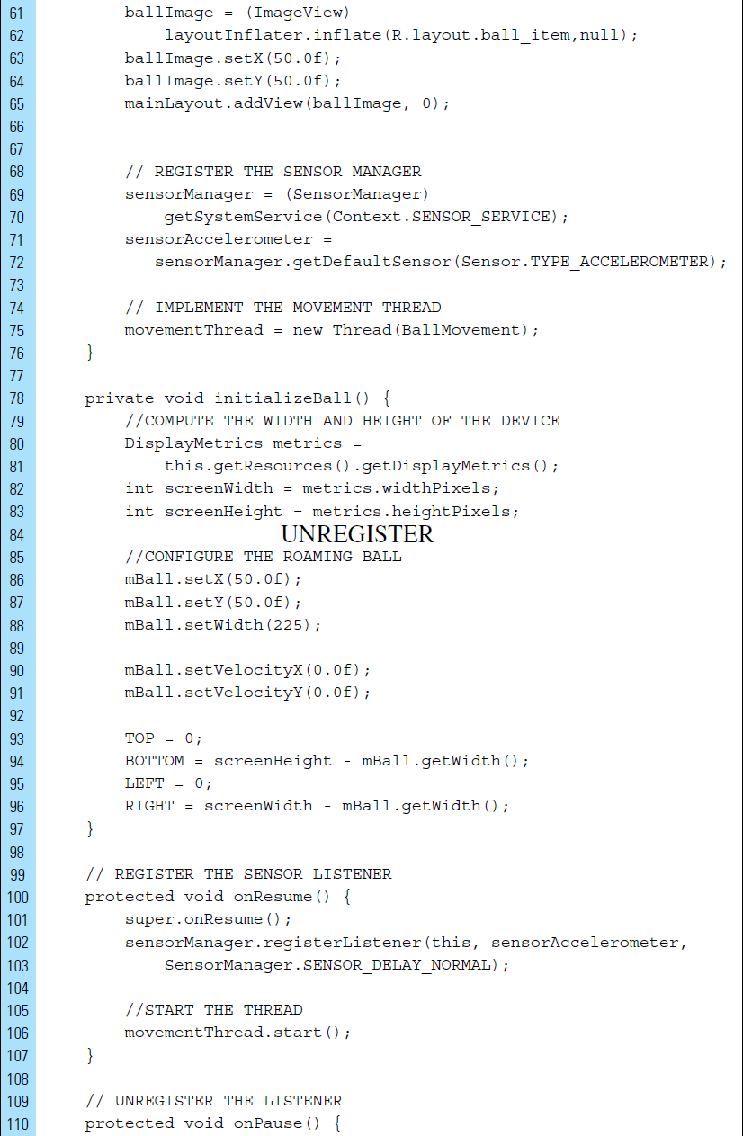
The launcher icon remains set to the Android default ic_launcher.png file. In addition to this graphic element, the background.png and ball.png have been added to the drawable directory. The complete structure for the application is shown in Figure 8-5. Given that this exercise is a simple experiment, a single activity, MyActivity, is used for the implementation of the accelerometer response, the thread mechanism, and control of the onscreen action. The Ball class, located in the Java source directory, is the data model for the ball located on the screen.
It is often a good idea to declare <uses-feature> elements for all of the features that an application requires. Declared <uses-feature> elements are informational only, which means that the Android system itself does not check for matching feature support on the device before installing an application. Services such as Google Play, however, may check the application’s <uses-feature> declarations as part of handling or interacting with the application.
Although the <uses-feature> element is activated only for devices running API Level 4 or higher, it is recommended that this element be included for all applications. Devices running older versions of the platform will ignore the element. To signal that your application uses or requires a hardware feature, declare each value in an android:name attribute in a separate <uses-feature> element. The following sensors can be specified:
android.hardware.sensor.accelerometer
android.hardware.sensor.barometer
android.hardware.sensor.compass
android.hardware.sensor.gyroscope
android.hardware.sensor.light
android.hardware.sensor.proximity
android.hardware.sensor.stepcounter
android.hardware.sensor.stepdetector
The code listing for AndroidManifest.xml is shown as follows:


Part 3: The User Interface
The user interface consists of a RelativeLayout that is used to store the image of the ball and text fields for the x-, y-, and z-axis accelerometer readings. strings.xml contains labels for the text fields and the content description for the ball image. The code listing for this file is shown as follows:

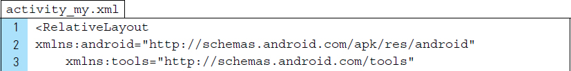
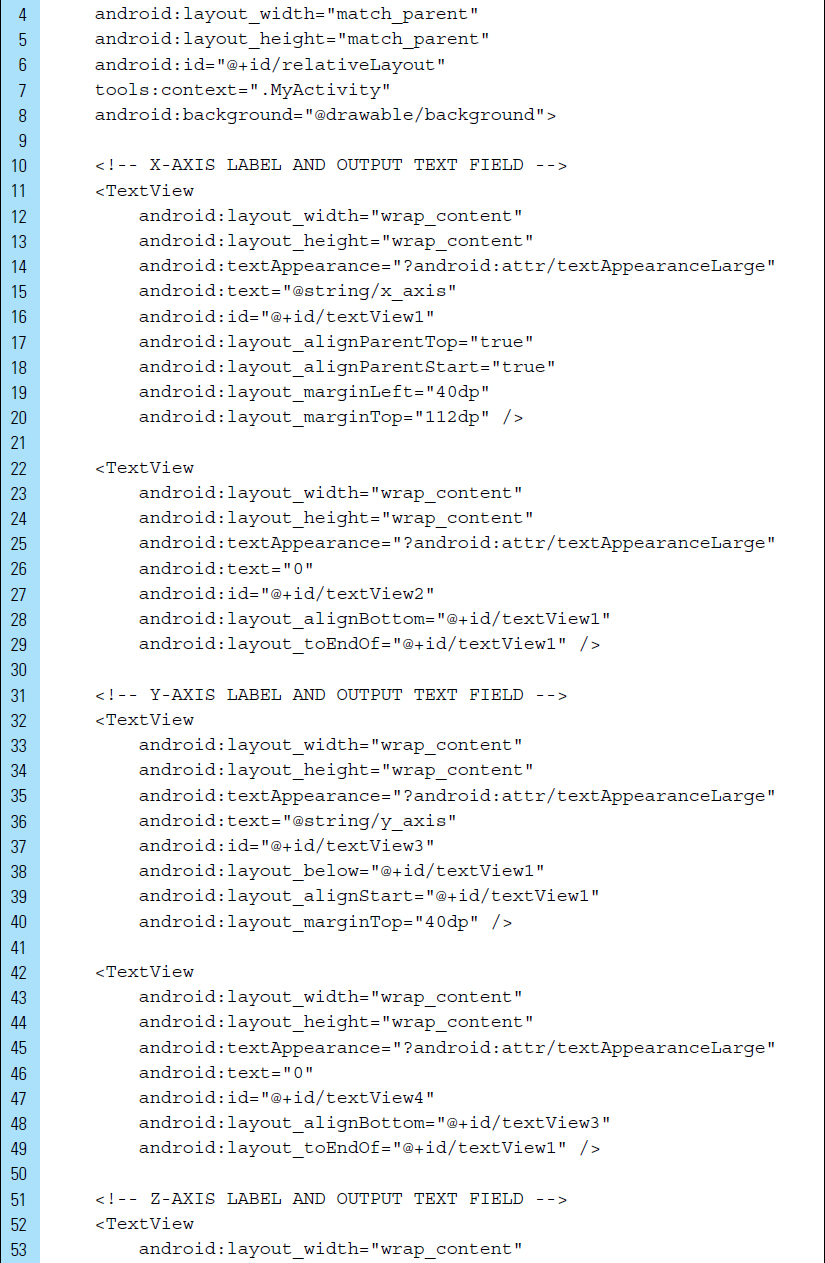
The layout file for the application is activity_my.xml. The graphical design for this layout is shown in Figure 8-6. The RelativeLayout root element is given an identifier name, @+id/relativeLayout, so that it may be referenced within the application’s main activity when adding an image of the ball during runtime. The TextViews in activity_my.xml are used for labels and output text fields. The accelerometer measurements along the three axes will be displayed in the TextViews: textView2 (x-axis), textView4 (y-axis), and textView6 (z-axis). The XML code listing for activity_my.xml is shown as follows:

The image of the ball is stored in an independent XML layout file, ball_item.xml. This allows the ball to be added to the screen during runtime. ball_item.xml, shown in Figure 8-7, requires an ImageView root element. The code listing for this layout file is shown as follows. Note that a content description is supplied to the root element on Line 6.


Part 4: Source Code for Application
The data model for the ball requires data members for representing an x, y position on the screen, the width of the ball, and its current velocity along the x- and y-axis. The Java code listing for the Ball class is as follows:


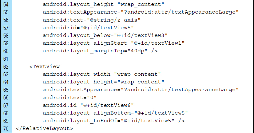
The SensorEventListener is implemented to monitor raw accelerometer data. Android will invoke the two callback methods onAccuracyChanged() and onSensorChanged() when the sensor’s accuracy changes and when the sensor reports a new value. Lines 1–139 of MyActivity.java are shown as follows:
Lines 100–113: |
|
|
Lines 102–103: |
The default data delay, |
|
|
|
20,000 microsecond delay |
|
|
60,000 microsecond delay |
|
|
0 microsecond delay |
|
It is also possible to specify the delay as a value in microseconds. Using a larger delay imposes a lower load on the processor and therefore uses less power. |
|
|
When you register a sensor with the |
|
Lines 128–129: |
Once a sensor has registered a new value, the measurement readings are applied to the ball’s velocity data members. |
|


Lines 140–172: |
|
Lines 174–180: |
|


■ 8.5 Accelerometer and Force
Force is an occurrence that is related to acceleration. Newton’s Second Law of Motion gives us an exact relationship between force, mass, and acceleration, which is expressed in the mathematical equation:
Force = Mass * Acceleration
Accelerometers are a natural choice for supplying information about the force applied to a device. Given a fixed mass, an Android device will experience an increase in force when the acceleration of the device is increased. When the accelerometer measures a zero force, the device is either still or moving at a constant speed. When the acceleration of the device is increased, such as a quick jerk of the hand, the accelerometer registers an increase in force. A decrease in movement is negative acceleration, or deceleration.
The accelerometer can efficiently report the combined effect of gravity. For example, to interpret certain gestures, such as an intended shake in the device, it may be necessary to remove the impact of gravity from the accelerometer readings and consider only acceleration engendered by the gesture.
The accelerometer is actually made up of three accelerometers, one for each axis: x, y, and z. Each one measures changes in velocity over time along a linear path. Combining all three accelerometers lets you detect accelerated force in any direction. While acceleration is a vector quantity, g-force is often expressed as a scalar, with positive g-forces pointing upward (indicating upward acceleration), and negative g-forces pointing downward.
Detecting the forces applied to a device requires the collection of accelerated movement on all three axes. This movement is measured in meters per second squared (the SI unit). The linear acceleration can be converted into a g-force measurement by neutralizing gravity, which is supplied by the constant SensorManager.GRAVITY_EARTH. To compute a directionless g-force measurement, the Pythagorean theorem can be applied to the different acceleration axes readings.
Detecting force from the accelerometer is an important information source in healthcare applications, such as an application that monitors and detects when an elderly person has fallen down.
■ Lab Example 8-2: Shake Experiment and the Magic Answer App
The Magic Answer application in this lab example explores the use of a shake gesture. A shake gesture requires an accelerometer and monitoring directionless force. As a gesture, a single shake is a movement that involves two specific elements: a shake action followed by a period of rest. To register as a shake gesture, the computed force of the shake action must measure above a declared threshold. Declaring a threshold allows the app to distinguish between an intended vigorous shake and an accidental movement of the device.
Part 1: The Design
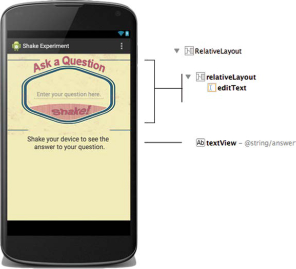
The Magic Answer application is similar in design to the popular toy, Magic Eight Ball. This application will be used to predict the answer to a “yes” or “no” question supplied by the user. When the user launches the application, a fixed layout appears that contains an EditText for input, a soft keyboard, and a TextView for output. The user enters the question and shakes the device to obtain a magic answer, as shown in Figure 8-8. The answer is generated randomly from a set of stored XML string values. Using the activity/rest/threshold model, the application can significantly reduce the possibility of responding to accidental or unwanted shaking.
Part 2: Application Structure and Setup
The settings for the application are as follows:
Application Name: |
Shake Experiment |
Project Name: |
ShakeExperiment |
Package Name: |
|
Android Form: |
Phone and Tablet |
Minimum SDK: |
API 18: Android 4.3 (Jelly Bean) |
Target SDK: |
API 21: Android 5.0 (Lollipop) |
Compile with: |
API 21: Android 5.0 (Lollipop) |
Activity Name: |
|
Layout Name: |
|

The Drawable folder contains the Android default launch icon, as well as the background image, background.png. The layout activity_my.xml is used for the user interface, featuring text fields for input and output. Three Java source files are required for this app. ShakeDetector is the implementation of the shake gesture. MagicAnswer is the data model for magic answers to the user’s questions. MyActivity serves as the controller, acting as the intermediary between the layout elements, the shake events, and magic answers. The final project structure for this application is shown in Figure 8-9.
The accelerometer is required hardware for this application. This is specified in the <uses-feature>, Lines 10–12, in the AndroidManifest.xml file. The XML code listing for this file is as follows:


Part 3: Resources
The strings.xml is used to declare possible answers to users’ questions. Magic answers, stored in a <string-array> XML structure, will be loaded into a MagicAnswer.class data object when the application is launched. In addition to strings.xml, color.xml is created to define the color used for the screen design. Both XML code listings are as follows:


colors.xml declares a yellow color that matches the background and is used to give the application a more polished look.

Part 4: The User Interface
The interface for the application requires two text elements: (1) an EditText for the user to input the question, and (2) a TextView to display the magic answer supplied once the user has shaken the device. Figure 8-10 shows the design and hierarchical structure of Views comprising the layout. The XML code listing for activity_my.xml is written as follows:

Part 5: Source Code for Application
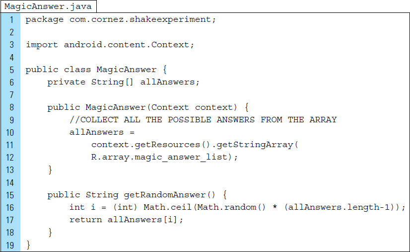
The class MagicAnswer.java will store and generate magic answers. When instantiated, a MagicAnswer object will collect all answers defined in the array named magic_answer_list declared within strings.xml. The method getRandomAnswer() will generate a random response when called upon by a shake gesture. The Java source code for MagicAnswer.java appears as follows:
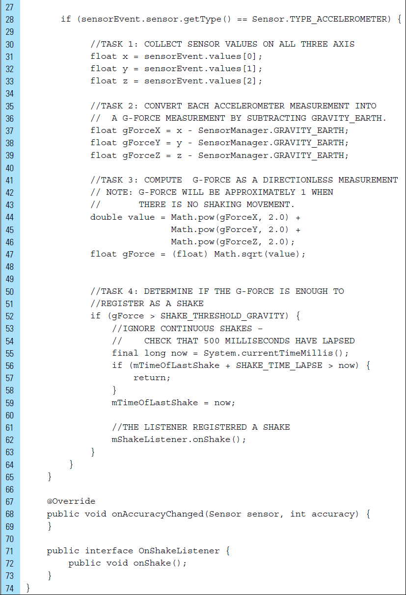
The objective of ShakeDetector.java is to listen for a sensor event and determine whether a valid shake gesture has occurred. The user must shake the device fairly vigorously to produce a magic answer. A simple movement of the device or a small accidental rotation should not register as a shake. We must implement controls to be sure the user is shaking the device on purpose. The ShakeDetector.java class is written as follows:
Line 8: |
The |
|
Lines 13–14: |
To trigger a new magic answer, the computed force of acceleration must be greater than a specified threshold level. In addition, the time between acceleration events must be within a fixed time. This will prevent the occurrence of accidental or constant shaking. |
|
Lines 25–66: |
The logic for a shake detection will be implemented in the |
|
Lines 30–33: |
G-force can be used to register as a shake. A shake gesture uses the accelerometer to detect movement in three directions: |
|
|
Left to right: |
|
|
Top to bottom: |
|
|
Forward to backward: |
|
Lines 35–39: |
All input vectors automatically include the Earth’s gravitation forces. The position of the device in three-dimensional space is irrelevant. In addition, it is unknown which of the vectors (x, y, or z) is affected by the Earth’s gravity. Therefore, gravitational effects can be neutralized. In this way, the app can respond to an intended shake. |
|
Lines 41–47: |
Rather than finding the main direction of the shake, the directionless g-force of the device’s movement can be computed. |
|
Lines 50–63: |
A shake is detected if the computed g-force is bigger than the force threshold and a significant amount of time has elapsed since the last acceleration change. |
|
|
Sensor data can change at a high rate, which means the system may call the |
|

MyActivity.java is the only Activity of this basic application. It serves as the controller for the application and is used to register and unregister the sensor listeners and interact with the user. The Java code listing appears as follows:
Lines 60–65: |
It is important to disable sensors when you do not need them (such as |


■ 8.6 Sensor Batching
Android offers sensor batching for the development of fitness and health applications. Hardware sensor batching is a technique that is designed to reduce the power consumed by sensors commonly used in fitness, location tracking, and monitoring service applications. Sensor batching allows hardware sensors to collect and deliver sensor-related data more efficiently in batches, rather than individually.
For example, consider an accelerometer-driven application, used for healthcare purposes, to track a user’s physical activity level. Assume that this application is designed to measure activity level as the number of steps the person takes. To detect steps, the application must capture readings from the accelerometer and distinguish the step pattern. Such an application ideally should run in the background, counting steps and tracking location. These tasks require that a process must remain in an active state, which can cause the battery life to lose power at a faster rate. With the release of Android 4.4, the use of sensor batching has reduced the impact of an active state process. Sensor batching provides optimization to decrease power consumed by ongoing sensor activities. When a sensor is in batch mode, the application processor is prevented from waking up to receive each event. Instead, these events can be grouped and processed together.
Collecting and delivering sensor events efficiently within batches, rather than individually as they are typically detected, lets the application processor remain in a low-power idle state until batches are delivered. It is possible to request batched events from any sensor using a standard event listener, as well as control the interval at which batches are received.
Sensor batching is ideal for low-power, long-running tasks, particularly for fitness and healthcare detection that requires efficient continuous monitoring, even while the screen is off and the system is asleep.
At the time of this writing in early 2015, sensor batching is not currently available on all Android devices.
8.6.1 Step Counter and Step Detector
Physical activity tracking is required for pedometer-type applications. Pedometer applications are generally designed to focus on step counting, but they can often be customized to consider other activities, such as running and stair climbing. To monitor physical activity accurately, such an application should be able to detect different types of activity.
Many Android mobile devices have been equipped with sensors that can be used to collect data for activity classification. To create a physical activity classification model, data are often required from several sensors, including the camera and GPS.
A simple approach to detecting and classifying physical activity requires the use of accelerometer data along with two activity classification sensors: the step detector and step counter.
The step detector can recognize when a user takes a step and then triggers an event as a result. By analyzing accelerometer input, this sensor can detect an individual step movement. Following each recognized step, it delivers an event with a value of 1.0 and a time-stamp, indicating when the step occurred. The constant TYPE_STEP_DETECTOR is used to specify the step detector.
The step counter, identified by the constant TYPE_STEP_COUNTER, can track the total number of steps taken since the last device reboot. It triggers an event for each detected step and adds to the accumulated number of steps since the sensor was first registered by the application. Step functionality, logic, and management are built into the platform and underlying hardware. This means there is no need to maintain your own detection algorithms in your application.
In the following segment of code, the sensor manager is used to access the sensors for a pedometer application. It should be noted that a TYPE_STEP_COUNTER event will occur with a higher latency than an event from a TYPE_STEP_DETECTOR. This is because the TYPE_STEP_COUNTER algorithm requires more processing to eliminate false positives. In this way, the TYPE_STEP_COUNTER may be slower to deliver events, but its results are often more accurate.

In this segment of code, a listener is registered for the step counter sensor in batch mode. If the maximum delay is set to zero, events will be delivered in a continuous mode without batching. In addition, the initial step counter value can be reset.

In the following code segment, onSensorChanged() is used to detect a step action.

■ 8.7 Composite Sensors
Android devices typically come equipped with three embedded sensors: a magnetometer, an accelerometer, and a gyroscope. These three sensors are base sensors and work independently of one another. Activating one of these sensors does not deactivate or reduce the rate of another base sensor.
Base sensors can be used in tandem to give developers flexibility in the creation of composite sensor types. When monitoring a physical environment, base sensors are often used jointly to create sensors that are finely tuned to an application’s needs. For example, when determining the direction a device is facing, an interface can rely on raw data provided by both an accelerometer and a magnetometer. This composite sensor feedback will determine a device’s position relative to the world’s frame of reference, as opposed to the application’s frame of reference.
Examples of composite sensor types include a game rotation vector sensor and geomagnetic rotation sensor. A composite game rotation vector relies on the underlying accelerometer and gyroscope base sensors. A geomagnetic rotation vector relies on the accelerometer and magnetometer. Table 8-3 shows a collection of composite sensors.
■ Lab Example 8-3: Geomagnetic Rotation—Compass
This lab example implements a geomagnetic rotation vector for measuring the orientation of an Android device relative to a north, south, east, and west direction. The completed application is a compass app, as shown in Figure 8-11.
Game rotation vector |
Measures the orientation of the device relative to the East-North-Up coordinates frame. Base class: accelerometer and gyroscope. |
Geomagnetic rotation vector |
This sensor is similar to game rotation vector; however, it is continuously powered and consumes a very low amount of battery compared with the game rotation vector (accelerometer and gyroscope). Game rotation vector is more sensitive than the geomagnetic rotation vector and is triggered by games, which receive 3-D tilt data as input. Base class: accelerometer and magnetometer. |
Gravity |
Measures the direction and magnitude of gravity in the device’s coordinates. Units are m/s2. The coordinate system is the same as is used for the acceleration sensor. When the device is at rest, the output of the gravity sensor should be identical to that of the accelerometer. Base class: accelerometer and gyroscope. |
Linear acceleration |
Indicates the linear acceleration of the device, not including gravity. The output is |
Step counter |
A time-stamp is used to indicate when a step has occurred. This corresponds to when the foot hits the ground, generating a high variation in acceleration. Base class: accelerometer. |
Step detector |
Both the step detector and the step counter will detect when the user is walking, running, and climbing up the stairs. The Step counter and detector events are not triggered when the user is biking or driving. Base class: accelerometer. |

Part 1: Application Structure and Setup
The settings for the application are as follows:
Application Name: |
Compass |
Project Name: |
Compass |
Package Name: |
|
Android Form: |
Phone and Tablet |
Minimum SDK: |
API 18: Android 4.3 (Jelly Bean) |
Target SDK: |
API 21: Android 5.0 (Lollipop) |
Compile with: |
API 21: Android 5.0 (Lollipop) |
Activity Name: |
|
Layout Name: |
|
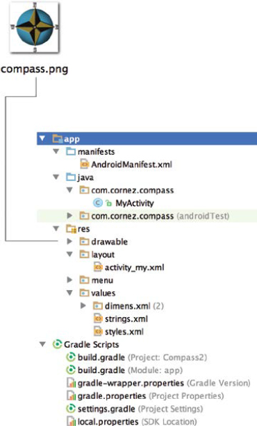
The launcher icon for this application is set to the Android default ic_launcher.png file. An additional PNG file, the compass image, has been added to the res/drawable directories.
The final project structure, shown in Figure 8-12, contains a single Activity and its associated layout XML user interface.
A geomagnetic rotation vector sensor is a composite sensor that will be defined by the accelerometer in tandem with the magnetometer. The application specifies each feature in a separate <uses-feature> element within the AndroidManifest file.
Lines 5 and 6 indicate that the application will use motion readings from an accelerometer and directional readings from a magnetometer (compass) on the device. In addition, a portrait screen orientation is set for the application.

Part 2: The User Interface
In addition to the default strings used in the application, strings.xml contains a description of the compass image that will be displayed to the user. The complete strings.xml file appears as follows:


The layout XML file associated with the launched activity, activity_my.xml, is designed to display a compass that will rotate as the user alters the direction. The layout design is shown in Figure 8-11 and the XML code appears as follows. The compass image is stored in the ImageView named imageView and is placed in the center of the screen.

Part 3: Source Code for Application
All the source code for the application is placed in MyActivity.java. This class implements a SensorEventListener.
Line 20: |
The compass image is declared. This image will be rotated when the sensor event listener indicates a change in orientation. |
Line 23: |
The compass angle is recorded in degrees. This variable is declared as a float data-type. |
Lines 30–31: |
The device’s sensor data will be collected and stored in the arrays |
Lines 44–47: |
The two sensors, |

onResume() is overridden to register the listeners for both accelerometer and magnetometer sensors. onPause() unregisters the listeners to save battery life.

When the registered listener triggers an onSensorChanged event, data are collected from the two base sensors, accelerometer and geomagnetic. The length and contents of the values array depend on a sensor type.
Line 73: |
Data values for the accelerometer are collected along the three axes in SI units. |
Line 76: |
Magnetic field data values for the Sensor.TYPE_MAGNETIC_FIELD are collected along three axes in micro-Tesla units. |
Lines 79–91: |
The rotation of the compass is computed using the inclination matrix (i) and the rotation matrix (r), provided by the method call |
Lines 86–88: |
If the rotation of the device has been altered, the rotation matrix (r) is used to compute the device’s new orientation. |
Line 91: |
The orientation change will be determined along the x-axis, as shown in Figure 8-13. |
Lines 94–98: |
An animation is produced to control the rotation of the compass. Rotation will occur in reverse, from the current degree to–degree. |
Lines 100–108: |
The duration of the animation is set, and the animation is applied. Once the animation is complete, the angle of the compass orientation is recorded. |


■ 8.8 Camera
The camera sensor is one of the most frequently used sensors on an Android device. Even though the camera is ubiquitous on mobile devices, not all Android devices contain a camera, even though this was a requirement at one time. The necessity of a camera on a device was relaxed when Android began to be used on set-top boxes. Set-top boxes are devices that allow users to listen to music, view content, and play games on their television sets.
To prevent an application that requires a camera from being installed on devices that do not feature a camera component, a <uses-feature> tag should be placed in the AndroidManifest file. This will allow Google Play to filter the appropriate devices. The android.hardware.camera feature is shown in the code line below:
![]()
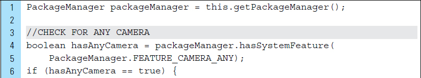
In addition to providing Google Play with the ability to filter out devices that do not meet an application’s sensor requirements, it is also important to check the availability of the camera within an activity that uses a camera feature. The existence of camera components can be verified by using PackageManager. Android devices often come equipped with multiple cameras. For example, a back-facing camera is most often used for taking typical photographs. A front-facing camera may also be available on a device because strategically it is highly suitable for making video calls. The availability of camera features can be identified with three constants:
|
The device has at least one camera or can support an external camera being connected to it. |
|
The device has a camera facing away from the screen. This is also referred to as a rear-facing camera. |
|
The device has a front-facing camera. |
The following segment of code illustrates the use of a PackageManager and a Toast to indicate which camera features are available. PackageManager is used to retrieve information related to the application packages that are currently installed on a device.
Camera sensors use arrays with millions of tiny light photosites to record a single image. Compared to other sensors, the incorporation of a camera sensor into an application requires the collection of a large amount of data. Before developing an application that uses a camera, the requirements for photo capturing and storage should be considered.
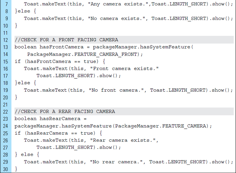
Captured photographs and video can be stored in various ways. For example, an application can allow or prohibit other applications from accessing the captured images or video. If the application is required to store its captured photographs or video in external storage, then writing to external storage requires special permission. Permission for writing to external storage can be set using a <uses-permission> tag in the AndroidManifest.xml file, as shown on Lines 1 and 2 below. When recording video, a <uses-permission> must also be set to record the audio element of the video. This is shown on Lines 4 and 5.
Two general options are available to developers when creating an application that requires capturing photos or video. Choosing the appropriate option depends upon how much camera flexibility is necessary for the application. For example, if the application requires limited camera control, the preferred option is to utilize the device’s built-in camera application. If integrating photos is only a small part of your application, one of the device’s installed camera applications can be used. The built-in camera application can be launched, using an explicit intent, and the resulting images can be stored for specific use by the current application or made available to other applications. Most Android-powered devices have at least one built-in camera.
In special cases, full camera integration and specialized control is required by an application. In these circumstances, a custom camera interface must be built. It should be noted that creating a customized camera user interface with special features is beyond the scope of this introductory textbook.
8.8.1 The Built-in Camera Application
Using a device’s built-in camera requires the camera application to be launched from an application’s activity. An Intent needs to be invoked to activate the external camera application, and the captured photograph or video can be accessed when focus is returned to the calling activity.
To access a captured image or video recording from a camera activity, the camera intent must be initiated using the startActivityForResult() call. As opposed to using startActivity() to initiate the intent, the call to start ActivityForResult() allows the activity to not only start the camera application, but also to receive the captured photo as a result. The captured photo can be accessed in the onActivityResult() callback.
The following segment of code illustrates how such an Intent is created and used to capture a photograph. The device’s camera application requests an image capture using MediaStore.ACTION_IMAGE_CAPTURE. MediaStore is a media provider that contains metadata for all available media on both internal and external storage devices. On Line 4, a path where the photograph will be stored is specified.
The startActivityForResult() method, on Line 7, starts the Intent that launches the camera application. The second argument in the startActivity ForResult() call is a request code that can be used to set a specific request, which can also be used to identify the action that took place. The request code in the code segment below is specfied as CAMERA_CAPTURE_PHOTO_REQUEST_CODE. This will be used to indicate that the camera will take a simple photograph.
The resolveActivity() method will return the activity class name that should execute the intent. This ensures that the intent can be safely handled by an activity.


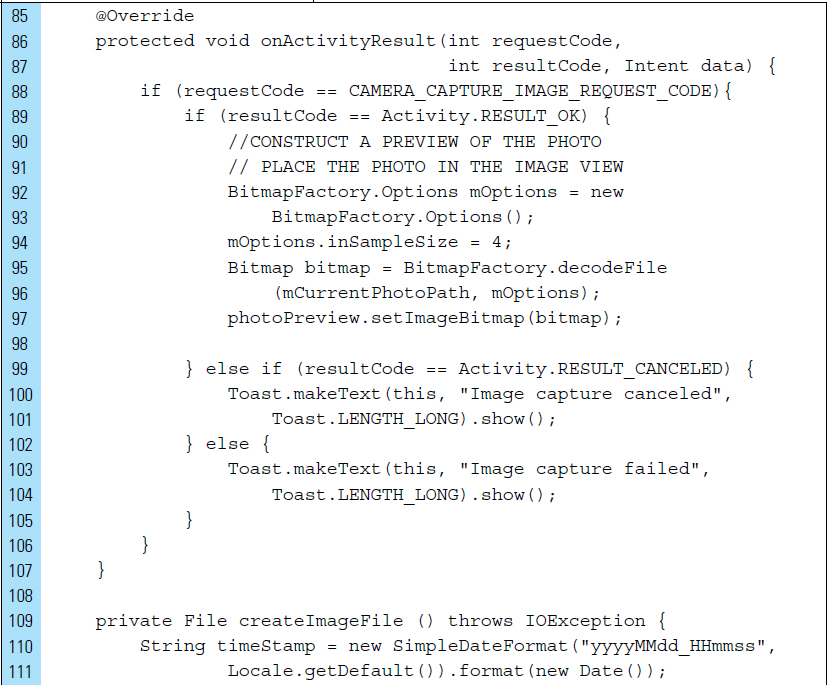
Once the built-in camera application has been launched from an activity and the user has completed the intended task of capturing video or a photograph, the user can exit the external camera application. Upon exiting the camera app, focus will be returned to the calling activity. Since the camera was launched using startActivityForResult(), the Android system will automatically call the activity’s onActivityResult(int requestCod, int resultCode, Intent data) method upon return. The original requestCode supplied to startActivityForResult() is also returned, making it easy to identify the specific request of the intent. For example, a requestCode can be used to identify whether the result is from a request to capture an image, such as CAMERA_CAPTURE_PHOTO_REQUEST_CODE, or a request to capture a video.
The resultCode parameter in onActivityResult() specifies the general outcome of the operation. For example, if the resultCode returns RESULT_OK, then the camera successfully captured a photo or video. A value of RESULT_CANCELED means the user backed out of the camera operation, or the camera failed to take a photo or record video for some reason.
The Intent data is used to return result data to the caller. The data parameter, on Line 3, carries the result data from the camera. Applications included with the Android platform offer their own APIs that you can count on for specific result data, where various data can be attached to Intent “extras.” The Camera app encodes and returns the captured photo as a Bitmap in the “data” extra, which is delivered to onActivityResult().
The following segment of code illustrates the retrieval of a photograph captured by the camera app. Line 12 places this bitmap in an ImageView.


BitmapFactory creates the imageBitmap object from various sources, including files, streams, and byte-arrays. Managing multiple full-sized images can be tricky with limited memory. If you find your application running out of memory after displaying just a few images, you can dramatically reduce the amount of dynamic heap used by expanding the JPEG into a memory array that is already scaled to match the size of the destination view. The following example method demonstrates this technique.
The method inSampleSize() requests the decoder to subsample the original image. If set to a value > 1, this method returns a smaller image to save memory. The sample size is the number of pixels in either dimension that correspond to a single pixel in the decoded bitmap. For example, inSampleSize == 4 returns an image that is 1/4 the width/height of the original, and 1/16 the number of pixels. Any value <= 1 is treated the same as 1. Note that the decoder uses a final value based on powers of 2; any other value will be rounded down to the nearest power of 2.

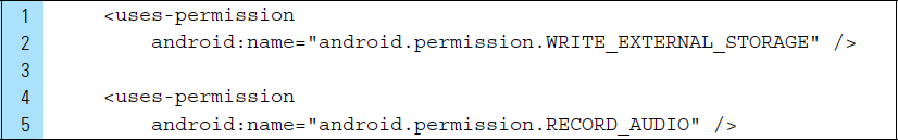
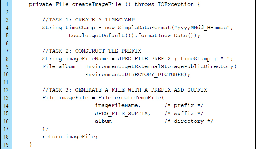
Once a photograph or video recording is captured, it should be saved on the device in the public external storage slot so that it may be accessible to other applications. The proper directory for shared photos is provided by getExternalStoragePublicDirectory(), with the DIRECTORY_PICTURES argument. This directory is shared among all applications. To read to and write from this location requires WRITE_EXTERNAL_STORAGE permission. The permission allows both reading and writing. If the photos taken by your app need to remain private to your application, you can instead use the directory provided by getExternalFilesDir(). In this case, the media scanner cannot access these files because they are private to your app.
The instructions in Lines 3–17 will create a fully qualified file name containing a time stamp, prefix, suffix, and directory.
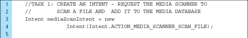
Adding a captured photograph to a Media Provider’s database makes it available in the Android Gallery application. This means that other applications will have access to it. This is performed using an Intent of type ACTION_MEDIA_SCANNER_SCAN_FILE.
The code segment shown below illustrates how a full-size photo is added to a specified album in the device’s photo gallery. This photo gallery relies on the Media Provider’s database, making it available in the Android Gallery application and to other apps. The path to the file will be contained in the mCurrentPhotoPath field, shown on Line 7.
If you choose to save media content to the directory provided by get-ExternalFilesDir(), the media scanner cannot access the files because they are private to your app.

■ Lab Example 8-4: Basic Camera
This lab example explores the usage of the built-in camera application for capturing photos. The application design, as shown in Figure 8-14, allows the user to launch the camera application by tapping the button labeled “Take a Photo.” Once the camera application launches, the user can take a photograph, which will be displayed as a small preview. The user then has the option of storing the photo in an album in the photo gallery.
Part 1: Application Structure and Setup
The Basic Camera application does not provide any special features and is just meant to take advantage of the built-in camera application. It is designed to work on phones and tablets running Android 4.4+ KitKat.
The settings for the application are as follows:
Application Name: |
Basic Camera |
Project Name: |
BasicCamera |
Package Name: |
|
Android Form: |
Phone and Tablet |
Minimum SDK: |
API 18: Android 4.3 (Jelly Bean) |
Target SDK: |
API 21: Android 5.0 (Lollipop) |
Compile with: |
API 21: Android 5.0 (Lollipop) |
Activity Name: |
|
Layout Name: |
|
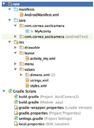
The final project structure for the Basic Camera is shown in Figure 8-15.
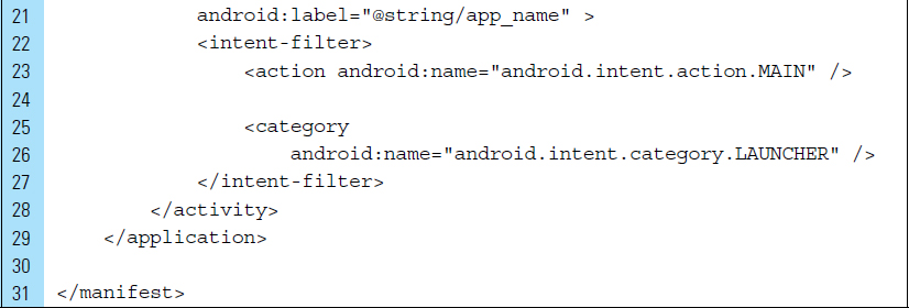
The orientation of the screen will be locked into portrait mode, which will be done in the AndroidManifest.xml file. To ensure proper device compatibility, it is important to add the <uses-feature> declaration, which describes the camera hardware as a device feature for this application. The required attribute on Line 7 specifies the camera hardware as a requirement. When declaring a camera hardware feature, a set of permissions must also be set to access the camera API. Requesting the permission grants your application access to the appropriate hardware and software. Permission is set to allow writing to external storage, which allows captured photographs to be saved.


Part 2: The User Interface
The values for this application are limited to strings. These strings are utilized for the buttons in the application’s interface. The XML code listing for strings.xml is as follows:

The application uses a single-user interface screen. The layout file activity_my.xml is associated with the activity MyActivity.java. The UI requirements include a button to launch the built-in camera application, an ImageView to display a preview of the photograph taken by the camera application, and a button to allow storage of the just-taken photo in an album so the user can access and manage it on the device. The XML code listing for the user interface is as follows:


Part 3: Source Code for Application
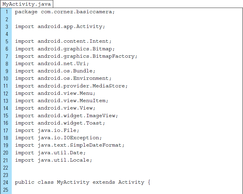
MyActivity.java contains the complete source code for the application. It should be noted that the activity must check the camera’s availability at runtime by calling hasSystemFeature(PackageManager.FEATURE_CAMERA). In order to save space and simplify the lab, this task is not performed in this lab example. The listing for this file appears as follows:
Lines 51–76: |
The |
Lines 54–55: |
An Intent to launch the default camera activity is created. This intent requests an image using the intent type |
Line 58: |
The resulting photo is temporarily stored in a file identified by a pathname. This file is set up in Lines 78–84. |
Lines 65–66: |
Using a camera intent to capture an image requires extra information. In this example, a |
Lines 69–70: |
The |

Lines 88–108: |
It is important to get the image back from the camera application. The Android camera application encodes the photo in the return |
Line 88: |
The |
Line 89: |
When the camera application exits, the |
Lines 92–96: |
A small preview of the photograph is constructed. Memory can be an issue when viewing captured photographs; therefore, it is usually a good idea to prescale the target bitmap into which the image file is decoded. |
The method call |
|
The camera application will save a full-size photo if a filename is provided. A captured photo is often saved on the device in public external storage so that it is accessible by other applications. |
|
Line 97: |
The content of the |
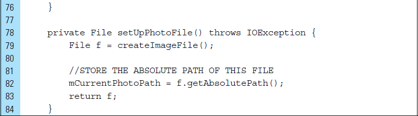
Lines 109–117: |
An image file is created. The name of the file is constructed as a unique name using a time-stamp combined with a prefix, suffix, and an album name within the photo gallery. |
Lines 119–129: |
An album directory named “ |
Lines 131–144: |
|


■ 8.9 Manipulating Photos
When creating applications that integrate built-in camera hardware, the resulting images may need to be edited or manipulated in some fashion. For example, users may be allowed to apply style filters to a captured image, or an application may require that an image be reconstructed with effects based on photography techniques.
A digital image is a two-dimensional array of pixels, each pixel containing a numeric value indicating variations of color. Traditional cameras on an Android device are engineered with filters that detect light that masks each pixel for only a single color: red, green, or blue. Editing an image, such as applying a filter, requires editing this pixel information.
A captured image can be manipulated by altering pixels, which store four values (red, green, blue, and alpha), with effects such as brightness, darkness, and grayscale or color conversions. Each of these values is stored in one byte of memory, with 0 representing no intensity and 255 representing full intensity. For example, a red value of 0 is no red at all, and a red value of 255 has the maximum amount of red. All of the colors that we can make in a picture are made up of combinations of red, green, and blue values, and each of those pixels sits at a specific (x, y) location in the photo.
The following color chips show several RGB examples.
|
Pure red contains the full intensity of red (255) and no intensity of green and blue. R: 255 G: 0 B: 0 |
|
Pure yellow contains the full intensity of red and green, but not blue. R: 255, G: 255, B: 0 |
|
Pure white is the combination of all three colors at full intensity. R: 255, G: 255, B: 255 |
|
Pure black contains the weakest intensity of wavelengths that correspond to red, green, and blue. R: 0, G: 0, B: 0 |
|
Shades of grey have equal intensities of red, green, and blue values. |
Figure 8-16 shows a collection of photographs. The original photograph, located in the upper-left corner, was manipulated in three ways. The first manipulation produced a yellow filter by maintaining the original intensities for red and green, and reducing the blue intensity by 50 percent. A pink filter was achieved by maintaining the original color intensities, with the exception of green, which is reduced by 50%. The final photograph was manipulated by reducing both red and green values.


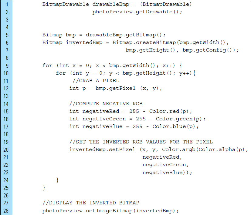
The Android Bitmap class, android.graphics.bitmap, is used for handling images, as shown in the previous lab example. The following segment of code illustrates how a color filter can be applied to a bitmap. The bitmap result of this code, shown in Figure 8-17, has been manipulated by swapping color values.

Lines 1–3: |
A drawable bitmap is instantiated and populated with the image stored within an ImageView, |
Line 5: |
|
Lines 6–7: |
A mutable bitmap object is instantiated with the same width and height as |
Lines 9–10: |
The Bitmap object, |
Line 11: |
getPixel () returns the color values at the specified x, y pixel location. |
Lines 12–14: |
Each color value for the red, green, and blue components is retrieved using |
Lines 16–18: |
Color values are swapped. Red will acquire the blue value, blue will acquire the green value, and green will acquire the red value. |
Line 20: |
|
Line 24: |
The content of the |

The Bitmap class provides a set of methods for handling the management and transformation of raw bitmaps decoded by the camera. The following is a list of the more common methods:
|
This method is used to copy a bitmap’s pixels into a new bitmap. It requires the original bitmap configuration as an argument and a Boolean value indicating whether the bitmap is mutable. |
|
There are multiple methods for creating a bitmap. At its most basic, |
|
Returns a new bitmap that captures the alpha values of the original bitmap. |
|
Returns the density, the scaling factor, of a given bitmap. It is also possible to set the density of a bitmap using |
|
Returns the number of bytes between rows of the native bitmap pixels. |
The simplest level adjustment that can be made to an image is to negate the image. In basic terms, this means converting white to black and black to white. For color bitmaps, this means adjusting colors by converting them to their complementary color. For example, the complement of red is cyan. The following segment of code illustrates the negating of color in a captured photograph, as shown in Figure 8-18.
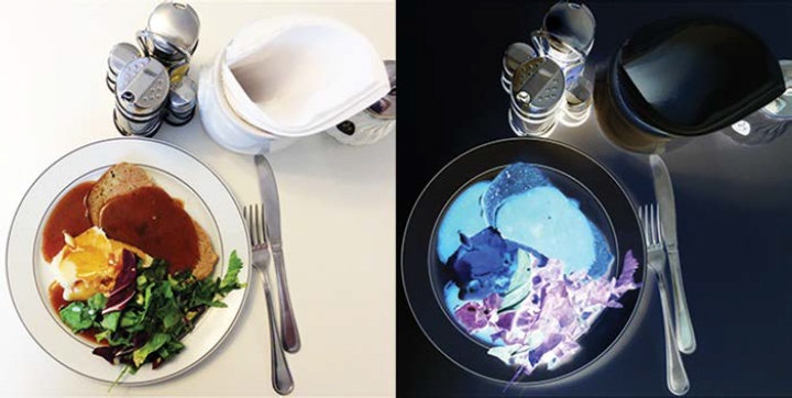
As each pixel is processed, the complement of the existing color values are produced by subtracting the red, green, and blue components from 255, the maximum intensity. For example, white will appear when the red component is 255, the green component is 255, and the blue component is 255. Black is produced when white is subtracted from 255, resulting in red: 0, green: 0, and blue: 0.
■ Lab Example 8-5: ASCII Camera Conversion Application
ASCII art consists of images pieced together from characters defined by the ASCII Standard Character Set. An ASCII Camera Converson application is a tool for converting captured photographs to ASCII art.
This lab example explores the creation of an ASCII conversion program that quantifies the grayscale value of each pixel in a photograph captured by the camera. A black and white text component will be created to contain assigned ASCII text characters that approximate the grayscale value. The application will generate a complete representation of a given photograph as a TextView containing a collection of characters, as shown in Figure 8-19.

Part 1: The Design and Application Structure
This application is designed to work with images, specifically photographs captured by the built-in camera, defined by pixel data. The ASCII art generated by this application uses a monospace font, where all characters are identical in width. Courier is the most popular monospace font, and is used in this lab exercise. The application produces the ASCII art by sampling each image pixel down to a grayscale value, which is then assigned a specific ASCII character. To keep the application as a simple lab exercise, the application uses only twelve different ASCII characters.
Part 2: Application Structure and Setup
The settings for the application are as follows:
Application Name: |
Ascii Camera |
Project Name: |
AsciiCamera |
Package Name: |
|
Android Form: |
Phone and Tablet |
Minimum SDK: |
API 18: Android 4.3 (Jelly Bean) |
Target SDK: |
API 21: Android 5.0 (Lollipop) |
Compile with: |
API 21: Android 5.0 (Lollipop) |
Activity Name: |
|
Layout Name: |
|
The launcher is set to the Android’s default ic_launcher.png file.
The structure for this application is simplified with a single Activity and no drawable images, as shown in Figure 8-20. The orientation of the screen is locked into portrait mode, as shown in the following AndroidManifest.xml file.
Lines 6–12: |
The |

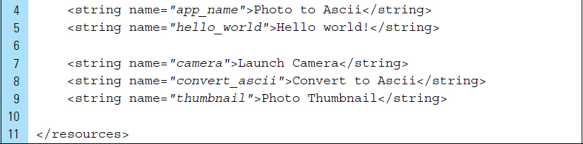
Part 3: The String Resources
The strings.xml file is the only resource requirement for the application. This file supplies the text labels for the UI buttons.

Part 4: The User Interface
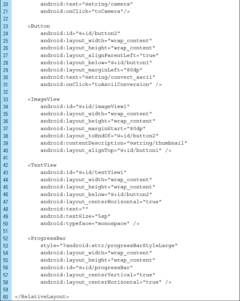
The layout design for the application is shown in Figure 8-21. activity_my.xml uses a RelativeLayout as the root tag. The UI components consist of a button to launch the built-in-camera, a small thumbnail view to see the returned camera photograph, and a button to perform the ASCII conversion. In addition, a TextView element is used to store and display the generated ASCII characters.
To appear as a small thumbnail view, a photograph is resized to a lower resolution, while maintaining its aspect ratio. As shown in Figure 8-21, the thumbnail view will be stored in the ImageView named imageView1.

Lines 12–21: |
The first button on the layout is used to launch the Camera application. This button, identified by |
Lines 23–31: |
The second button on the layout is used to convert a captured photograph into ASCII artwork. This button is identified by |
Lines 33–40: |
The |
Lines 42–50: |
The generated ASCII artwork is a text element that contains ASCII text characters. This string of characters, once generated, will be displayed in the TextView element named |
Lines 52–58: |
While the application is processing the photograph and generating the ASCII artwork, a progress bar will appear. This provides the user with rudimentary feedback about the conversion progress; that is, it is an indication that a process is occurring. |

Part 5: Source Code for Application
The conversion feature of the application requires images captured by the built-in camera. The photo image pixel data are analyzed in pairs of pixels. This means that every other pixel within the photograph is analyzed and then represented by an ASCII character. It is crucial that the original photograph be resized to a lower resolution. If the resolution of the JPEG image is maintained at its original size, the resulting text may have far too many rows and columns of characters to fit on a small-screen device.
Lines 33–34: |
A request code for capturing an image by the camera is defined as a constant. This request code will be used by the |
Lines 37–41: |
The two objects identified by |
Lines 52–54: |
References to the layout UI components are set for later management by the application. |
Line 57: |
Until the camera takes a photograph, an ASCII conversion is not allowed. This button is disabled. |
Line 60: |
The progress bar is used solely for the purpose of notifying the user that an ASCII conversion process is taking place. This UI component will be set directly before and after the conversion. At the launch of the application, the progress bar must be hidden. |
Lines 64–68: |
The |
Lines 73–99: |
A call to |


Lines 101–104: |
The When loading and processing large bitmaps, an AsyncTask should be used to perform the work off the main UI thread. This is particularly necessary when the bitmap is accessed from external storage. The AsyncTask class can execute much of the processing work in a background thread and publish the results back on the UI thread. |
Line 109: |
The ASCII artwork is built using a simple |
Lines 112–124: |
Prior to processing the photograph, all the buttons on the application are disabled. In addition, the progress bar is made visible to the user. |
Lines 129–136: |
Pixels will be read from the |
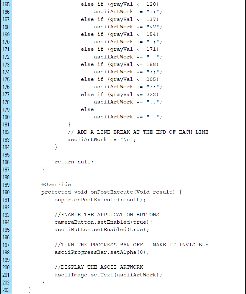
Lines 138–187: |
The ASCII artwork is built pixel by pixel. |
Lines 146–151: |
The color values for individual pixels from the bitmap object are normalized to find a grayscale value. The average of red, green, and blue components of color gives its gray factor. |
Lines 151–180: |
ASCII characters have been selected based on their brightness and weight. These characters have been assigned to represent gray values found in a typical photograph. |
Line 183: |
At the end of each line in a grid of pixels, a new line must be added to the ASCII artwork. |
Lines 190–202: |
During the postexecution of the |
Line 198: |
In addition, the |


A screen snapshot can be taken of the final artwork. The following code segment loads a bitmap from the TextView storing the ASCII characters:


■ Exercises
Describe the three categories of sensors found in an Android device.
List two motion sensors.
Explain the difference between a gyroscope and an accelerometer.
Describe three common environmental sensors found in an Android device.
Describe how Sensor and SensorManager are used to work with a device’s sensors.
A SensorEvent object includes specific information about a sensor event. Name four elements of information included in this object.
Name the two abstract methods that must be implemented in the Sensor-EventListener interface.
In the code segment below, explain the use of the value stored in the variable n.

Briefly explain how information can be accessed about the forces applied to an Android device.
What is sensor batching and why is it useful?
Briefly explain how a Step Counter differs from a Step Detector.
Provide an example of a composite sensor. Explain how a device uses a composite sensor.
Briefly list the sensors used in a compass application that determines the direction the device is facing.
List the three constants that identify camera categories on an Android device. Briefly describe the difference between FEATURE_CAMERA and FEATURE_CAMERA_FRONT.
Name the <uses-permission> attributes for storing an image or photograph to external storage.