
Telecommunications Evolution
Telephone systems have been around for about 100 years, and they started as copper-based analog systems. Central switching offices connected individual telephones manually (via human operators) at first, and later by using electronic switching equipment. After two telephones were connected, they had an end-to-end connection (end-to-end circuit). Multiple phone calls were divided up and placed on the same wire, which is called multiplexing. Multiplexing is a method of combining multiple channels of data over a single transmission path. The transmission is so fast and efficient that the ends do not realize they are sharing a line with many other entities. They think they have the line all to themselves.
In the mid-1960s, digital phone systems emerged with T1 trunks, which carried 24 voice communication calls over two pairs of copper wires. This provided a 1.544-Mbps transmission rate, which brought quicker service, but also the capability to put more multiplexed calls on one wire. When calls take place between switching offices (say, local phone calls), they are multiplexed on trunks such as T1 lines. When more bandwidth is needed, the trunks can be implemented on T3 lines, which can carry up to 28 T1 lines.
The next entity to join the telecommunications party was fiber optics, which enabled even more calls to be multiplexed on one trunk line over longer distances. Then came optical carrier technologies such as SONET, which is a standard for telecommunications transmission over fiber-optic cables. This standard sets up the necessary parameters for transporting digital information over optical systems. Telecommunications carriers used this technology to multiplex lower-speed optical links into higher-speed links, similar to how lower-speed LANs connect to higher-speed WAN links today. Figure 4-67 shows an example of SONET rings connected together and how telecommunications carriers can provide telephone and Internet access to companies and individuals in large areas. The SONET standard enables all carriers to interconnect.
The next evolutionary step in telecommunications history is Asynchronous Transfer Mode (ATM). ATM encapsulates data in fixed cells and can be used to deliver data over a SONET network. The analogy of a highway and cars is used to describe the SONET and ATM relationship. SONET is the highway that provides the foundation (or network) for the cars—the ATM packets—to travel on.

Figure 4-67 SONET technology enables several optical communication loops to communicate.
ATM is a high-speed network technology that is used in WAN implementations by carriers, ISPs, and telephone companies. ATM uses a fixed cell size instead of the variable frame size employed by earlier technologies. This fixed size provides better performance and a reduced overhead for error handling. (More information on ATM technology is provided in the “ATM” section a little later.)
The following is a quick snapshot of telecommunications history:
• Copper lines carry purely analog signals.
• T1 lines carry up to 24 conversations.
• T3 lines carry up to 28 T1 lines.
• Fiber optics and the SONET network.
• ATM over SONET.
SONET was developed in the United States to achieve a data rate around 50 Mbps to support the data flow from T1 lines (1.544 Mbps) and T3 lines (44.736 Mbps). Data travels over these T-carriers as electronic voltage to the edge of the SONET network. Then the voltage must be converted into light to run over the fiber-optic carrier lines, known as optical carrier (OC) lines. Each OC-1 frame runs at a signaling rate of 51.84 Mbps, with a throughput of 44.738 Mbps.

NOTE Optical carrier lines can provide different bandwidth values: OC-1 = 51.84 Mbps, OC-3 = 155.52 Mbps, OC-12 = 622.08 Mbps, and so on.
Europe has a different infrastructure and chose to use Synchronous Digital Hierarchy (SDH), which supports E1 lines (2.048 Mbps) and E3 lines (34.368 Mbps). SONET is the standard for North America, while SDH is the standard for the rest of the world. SDH and SONET are similar but just different enough to be incompatible. For communication to take place between SDH and SONET lines, a gateway must do the proper signaling translation.
You’ve had only a quick glimpse at an amazingly complex giant referred to as telecommunications. Many more technologies are being developed and implemented to increase the amount of data that can be efficiently delivered in a short period of time.
Dedicated Links
A dedicated link is also called a leased line or point-to-point link. It is one single link that is pre-established for the purposes of WAN communications between two destinations. It is dedicated, meaning only the destination points can communicate with each other. This link is not shared by any other entities at any time. This was the main way companies communicated in the past, because not as many choices were available as there are today. Establishing a dedicated link is a good idea for two locations that will communicate often and require fast transmission and a specific bandwidth, but it is expensive compared to other possible technologies that enable several companies to share the same bandwidth and also share the cost. This does not mean that dedicated lines are not in use; they definitely are used, but many other options are now available, including X.25, frame relay, MPLS, and ATM technologies.
T-Carriers
T-carriers are dedicated lines that can carry voice and data information over trunk lines. They were developed by AT&T and were initially implemented in the early 1960s to support pulse-code modulation (PCM) voice transmission. This was first used to digitize the voice over a dedicated, point-to-point, high-capacity connection line. The most commonly used T-carriers are T1 lines and T3 lines. Both are digital circuits that multiplex several individual channels into a higher-speed channel.
These lines can have multiplex functionality through time-division multiplexing (TDM). What does this multiplexing stuff really mean? It means that each channel gets to use the path only during a specific time slot. It’s like having a time-share property on the beach; each co-owner gets to use it, but only one can do so at a time and can only remain for a fixed number of days. Consider a T1 line, which can multiplex up to 24 channels. If a company has a PBX connected to a T1 line, which in turn connects to the telephone company switching office, 24 calls can be chopped up and placed on the T1 line and transferred to the switching office. If this company did not use a T1 line, it would need 24 individual twisted pairs of wire to handle this many calls.
As shown in Figure 4-68, data is input into these 24 channels and transmitted. Each channel gets to insert up to 8 bits into its established time slot. Twenty-four of these 8-bit time slots make up a T1 frame. That does not sound like much information, but 8,000 frames are built per second. Because this happens so quickly, the receiving end does not notice a delay and does not know it is sharing its connection and bandwidth with up to 23 other devices.
Originally, T1 and T3 lines were used by the carrier companies, but they have been replaced mainly with optical lines. Now T1 and T3 lines feed data into these powerful and super-fast optical lines. The T1 and T3 lines are leased to companies and ISPs that need high-capacity transmission capability. Sometimes, T1 channels are split up between companies who do not really need the full bandwidth of 1.544 Mbps. These are called fractional T lines. The different carrier lines and their corresponding characteristics are listed in Table 4-12.

Figure 4-68 Multiplexing puts several phone calls, or data transmissions, on the same wire.

Table 4-12 A T-Carrier Hierarchy Summary Chart
As mentioned earlier, dedicated lines have their drawbacks. They are expensive and inflexible. If a company moves to another location, a T1 line cannot easily follow it. A dedicated line is expensive because companies have to pay for a dedicated connection with a lot of bandwidth even when they do not use the bandwidth. Not many companies require this level of bandwidth 24 hours a day. Instead, they may have data to send out here and there, but not continuously.
The cost of a dedicated line is determined by the distance to the destination. A T1 line run from one building to another building 2 miles away is much cheaper than a T1 line that covers 50 miles or a full state.
E-Carriers
E-carriers are similar to T-carrier telecommunication connections, where a single physical wire pair can be used to carry many simultaneous voice conversations by time-division multiplexing. Within this technology 30 channels interleave 8 bits of data in a frame. While the T-carrier and E-carrier technologies are similar, they are not interoperable. E-carriers are used by European countries.
The E-carrier channels and associated rates are shown in Table 4-13.
The most commonly used channels used are E1 and E3 and fractional E-carrier lines.
Optical Carrier
High-speed fiber-optic connections are measured in optical carrier (OC) transmission rates. The transmission rates are defined by rate of the bit stream of the digital signal and are designated by an integer value of the multiple of the basic unit of rate. They are generically referred to as OCx, where the “x” represents a multiplier of the basic OC-1 transmission rate, which is 51.84 Mbps. The carrier levels and speeds are shown in Table 4-14.

Table 4-13 E-carrier Characteristics

Table 4-14 OC Transmission Rates
Small and medium-sized companies that require high-speed Internet connectivity may use OC-3 or OC-12 connections. Service providers that require much larger amounts of bandwidth may use one or more OC-48 connections. OC-192 and greater connections are commonly used for the Internet backbone, which connects the largest networks in the world together.
Here are some other types of multiplexing functionalities you should be aware of:
Statistical time-division multiplexing (STDM):
• Transmits several types of data simultaneously across a single transmission cable or line (such as a T1 or T3 line).
• STDM analyzes statistics related to the typical workload of each input device (printer, fax, computer) and determines in real time how much time each device should be allocated for data transmission.
Frequency-division multiplexing (FDM):
• An available wireless spectrum is used to move data.
• Available frequency band is divided into narrow frequency bands and used to have multiple parallel channels for data transfer.

Wave-division multiplexing (WDM):
• Used in fiber-optic communication.
• Multiplexes a number of optical carrier signals onto a single optical fiber.
WAN Technologies
Several varieties of WAN technologies are available to companies today. The information that a company evaluates to decide which is the most appropriate WAN technology for it usually includes functionality, bandwidth demands, service level agreements, required equipment, cost, and what is available from service providers. The following sections go over some of the WAN technologies available today.
CSU/DSU
A channel service unit/data service unit (CSU/DSU) is required when digital equipment will be used to connect a LAN to a WAN. This connection can take place with T1 and T3 lines, as shown in Figure 4-69. A CSU/DSU is necessary because the signals and frames can vary between the LAN equipment and the WAN equipment used by service providers.

Figure 4-69 A CSU/DSU is required for digital equipment to communicate with telecommunications lines.
The DSU device converts digital signals from routers, switches, and multiplexers into signals that can be transmitted over the service provider’s digital lines. The DSU device ensures that the voltage levels are correct and that information is not lost during the conversion. The CSU connects the network directly to the service provider’s line. The CSU/DSU is not always a separate device and can be part of a networking device.
The CSU/DSU provides a digital interface for data terminal equipment (DTE), such as terminals, multiplexers, or routers, and an interface to the data circuit-terminating equipment (DCE) device, such as a carrier’s switch. The CSU/DSU basically works as a translator and, at times, as a line conditioner.
Switching
Dedicated links have one single path to traverse; thus, there is no complexity when it comes to determining how to get packets to different destinations. Only two points of reference are needed when a packet leaves one network and heads toward the other. It gets much more complicated when thousands of networks are connected to each other, which is often when switching comes into play.
Two main types of switching can be used: circuit switching and packet switching. Circuit switching sets up a virtual connection that acts like a dedicated link between two systems. ISDN and telephone calls are examples of circuit switching, which is shown in the lower half of Figure 4-70.
When the source system makes a connection with the destination system, they set up a communication channel. If the two systems are local to each other, fewer devices need to be involved with setting up this channel. The farther the two systems are from each other, the more the devices are required to be involved with setting up the channel and connecting the two systems.

Figure 4-70 Circuit switching provides one road for a communication path, whereas packet switching provides many different possible roads.
An example of how a circuit-switching system works is daily telephone use. When one person calls another, the same type of dedicated virtual communication link is set up. Once the connection is made, the devices supporting that communication channel do not dynamically move the call through different devices, which is what takes place in a packet-switching environment. The channel remains configured at the original devices until the call (connection) is done and torn down.
Packet switching, on the other hand, does not set up a dedicated virtual link, and packets from one connection can pass through a number of different individual devices (see the top of Figure 4-70), instead of all of them following one another through the same devices. Some examples of packet-switching technologies are the Internet, X.25, and frame relay. The infrastructure that supports these methods is made up of routers and switches of different types. They provide multiple paths to the same destinations, which offers a high degree of redundancy.
In a packet-switching network, the data is broken up into packets containing frame check sequence (FCS) numbers. These packets go through different devices, and their paths can be dynamically altered by a router or switch that determines a better route for a specific packet to take. Once the packets are received at the destination computer, all the packets are reassembled according to their FCS numbers and processed.
Because the path a packet will take in a packet-switching environment is not set in stone, there could be variable delays when compared to a circuit-switching technology. This is okay, because packet-switching networks usually carry data rather than voice. Because voice connections clearly detect these types of delays, in many situations a circuit-switching network is more appropriate for voice connections. Voice calls usually provide a steady stream of information, whereas a data connection is “burstier” in nature. When you talk on the phone, the conversation keeps a certain rhythm. You and your friend do not talk extremely fast and then take a few minutes in between conversations to stop talking and create a void with complete silence. However, this is usually how a data connection works. A lot of data is sent from one end to the other at one time, and then dead time occurs until it is time to send more data.
NOTE Voice over IP (VoIP) does move voice data over packet-switched environments. This technology is covered in the section “Multiservice Access Technologies,” later in the chapter.
Frame Relay
For a long time, many companies used dedicated links to communicate with other companies. Company A had a pipeline to company B that provided a certain bandwidth 24 hours a day and was not used by any other entities. This was great because only the two companies could use the line, so a certain level of bandwidth was always available, but it was expensive and most companies did not use the full bandwidth each and every hour the link was available. Thus, the companies spent a lot of money for a service they did not use all the time. Later, to avoid this unnecessary cost, companies turned to using frame relay instead of dedicated lines.

EXAM TIP Frame relay is an obsolescent technology. It is still in limited use, however, and you should be familiar with it for the CISSP exam.
Frame relay is a WAN technology that operates at the data link layer. It is a WAN solution that uses packet-switching technology to let multiple companies and networks share the same WAN medium, devices, and bandwidth. Whereas direct point-to-point links have a cost based on the distance between the endpoints, the frame relay cost is based on the amount of bandwidth used. Because several companies and networks use the same medium and devices (routers and switches), the cost can be greatly reduced per company compared to dedicated links.
If a company knows it will usually require a certain amount of bandwidth each day, it can pay a certain fee to make sure this amount of bandwidth is always available to it. If another company knows it will not have a high bandwidth requirement, it can pay a lower fee that does not guarantee the higher bandwidth allocation. This second company will have the higher bandwidth available to it anyway—at least until that link gets busy, and then the bandwidth level will decrease. (Companies that pay more to ensure that a higher level of bandwidth will always be available pay a committed information rate, or CIR.)
Two main types of equipment are used in frame relay connections: DTE and DCE, both of which were previously introduced in the discussion of CSU/DSU. The DTE is usually a customer-owned device, such as a router or switch, that provides connectivity between the company’s own network and the frame relay network. DCE is the service provider’s device, or telecommunications company’s device, that does the actual data transmission and switching in the frame relay cloud. So the DTE is a company’s ramp onto the frame relay network, and the DCE devices actually do the work within the frame relay cloud.
The frame relay cloud is the collection of DCE devices that provides switching and data communications functionality. Several service providers offer this type of service, and some providers use other providers’ equipment—it can all get confusing because a packet can take so many different routes. This collection is called a cloud to differentiate it from other types of networks and because when a packet hits this cloud, users do not usually know the route their frames will take. The frames will be sent either through permanent or switched virtual circuits that are defined within the DCE or through carrier switches.
NOTE The term cloud is used in several technologies: Internet cloud, ATM cloud, frame relay cloud, cloud computing, etc. The cloud is like a black box—we know our data goes in and we know it comes out, but we do not normally care about all the complex things that are taking place internally.
Frame relay is an any-to-any service that is shared by many users. As stated earlier, this is beneficial because the costs are much lower than those of dedicated leased lines. Because frame relay is shared, if one subscriber is not using its bandwidth, it is available for others to use. On the other hand, when traffic levels increase, the available bandwidth decreases. This is why subscribers who want to ensure a certain bandwidth is always available to them pay a higher CIR.
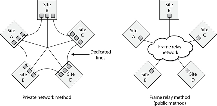
Figure 4-71 A private network connection requires several expensive dedicated links. Frame relay enables users to share a public network.
Figure 4-71 shows five sites being connected via dedicated lines versus five sites connected through the frame relay cloud. The first solution requires many dedicated lines that are expensive and not flexible. The second solution is cheaper and provides companies much more flexibility.
Virtual Circuits
Frame relay (and X.25) forwards frames across virtual circuits. These circuits can be either permanent, meaning they are programmed in advance, or switched, meaning the circuit is quickly built when it is needed and torn down when it is no longer needed. The permanent virtual circuit (PVC) works like a private line for a customer with an agreed-upon bandwidth availability. When a customer decides to pay for the CIR, a PVC is programmed for that customer to ensure it will always receive a certain amount of bandwidth.
Unlike PVCs, switched virtual circuits (SVCs) require steps similar to a dial-up and connection procedure. The difference is that a permanent path is set up for PVC frames, whereas when SVCs are used, a circuit must be built. It is similar to setting up a phone call over the public network. During the setup procedure, the required bandwidth is requested, the destination computer is contacted and must accept the call, a path is determined, and forwarding information is programmed into each switch along the SVC’s path. SVCs are used for teleconferencing, establishing temporary connections to remote sites, data replication, and voice calls. Once the connection is no longer needed, the circuit is torn down and the switches forget it ever existed.
Although a PVC provides a guaranteed level of bandwidth, it does not have the flexibility of an SVC. If a customer wants to use her PVC for a temporary connection, as mentioned earlier, she must call the carrier and have it set up, which can take hours.
X.25
X.25 is an older WAN protocol that defines how devices and networks establish and maintain connections. Like frame relay, X.25 is a switching technology that uses carrier switches to provide connectivity for many different networks. It also provides an any-to-any connection, meaning many users use the same service simultaneously. Subscribers are charged based on the amount of bandwidth they use, unlike dedicated links, for which a flat fee is charged.
Data is divided into 128 bytes and encapsulated in High-level Data Link Control (HDLC) frames. The frames are then addressed and forwarded across the carrier switches. Much of this sounds the same as frame relay—and it is—but frame relay is much more advanced and efficient when compared to X.25, because the X.25 protocol was developed and released in the 1970s. During this time, many of the devices connected to networks were dumb terminals and mainframes, the networks did not have built-in functionality and fault tolerance, and the Internet overall was not as foundationally stable and resistant to errors as it is today. When these characteristics were not part of the Internet, X.25 was required to compensate for these deficiencies and to provide many layers of error checking, error correcting, and fault tolerance. This made the protocol fat, which was required back then, but today it slows down data transmission and provides a lower performance rate than frame relay or ATM.
ATM
Asynchronous Transfer Mode (ATM) is another switching technology, but instead of being a packet-switching method, it uses a cell-switching method. ATM is a high-speed networking technology used for LAN, MAN, WAN, and service provider connections. Like frame relay, it is a connection-oriented switching technology, and creates and uses a fixed channel. IP is an example of a connectionless technology. Within the TCP/IP protocol suite, IP is connectionless and TCP is connection oriented. This means IP segments can be quickly and easily routed and switched without each router or switch in between having to worry about whether the data actually made it to its destination—that is TCP’s job. TCP works at the source and destination ends to ensure data was properly transmitted, and it resends data that ran into some type of problem and did not get delivered properly. When using ATM or frame relay, the devices in between the source and destination have to ensure that data gets to where it needs to go, unlike when a purely connectionless protocol is being used.
Since ATM is a cell-switching technology rather than a packet-switching technology, data is segmented into fixed-size cells of 53 bytes instead of variable-size packets. This provides for more efficient and faster use of the communication paths. ATM sets up virtual circuits, which act like dedicated paths between the source and destination. These virtual circuits can guarantee bandwidth and QoS. For these reasons, ATM is a good carrier for voice and video transmission.
ATM technology is used by carriers and service providers, and is the core technology of the Internet, but ATM technology can also be used for a company’s private use in backbones and connections to the service provider’s networks.
Traditionally, companies used dedicated lines, usually T-carrier lines, to connect to the public networks. However, companies have also moved to implementing an ATM switch on their network, which connects them to the carrier infrastructure. Because the fee is based on bandwidth used instead of a continual connection, it can be much cheaper. Some companies have replaced their Fast Ethernet and FDDI backbones with ATM. When a company uses ATM as a private backbone, the company has ATM switches that take the Ethernet, or whatever data link technology is being used, and frame them into the 53-byte ATM cells.
Quality of Service Quality of Service (QoS) is a capability that allows a protocol to distinguish between different classes of messages and assign priority levels. Some applications, such as video conferencing, are time sensitive, meaning delays would cause unacceptable performance of the application. A technology that provides QoS allows an administrator to assign a priority level to time-sensitive traffic. The protocol then ensures this type of traffic has a specific or minimum rate of delivery.
QoS allows a service provider to guarantee a level of service to its customers. QoS began with ATM and then was integrated into other technologies and protocols responsible for moving data from one place to another. Four different types of ATM QoS services (listed next) are available to customers. Each service maps to a specific type of data that will be transmitted.
• Constant bit rate (CBR) A connection-oriented channel that provides a consistent data throughput for time-sensitive applications, such as voice and video applications. Customers specify the necessary bandwidth requirement at connection setup.
• Variable bit rate (VBR) A connection-oriented channel best used for delay-insensitive applications because the data throughput flow is uneven. Customers specify their required peak and sustained rate of data throughput.
• Unspecified bit rate (UBR) A connectionless channel that does not promise a specific data throughput rate. Customers cannot, and do not need to, control their traffic rate.
• Available bit rate (ABR) A connection-oriented channel that allows the bit rate to be adjusted. Customers are given the bandwidth that remains after a guaranteed service rate has been met.
ATM was the first protocol to provide true QoS, but as the computing society has increased its desire to send time-sensitive data throughout many types of networks, developers have integrated QoS into other technologies.
QoS has three basic levels:
• Best-effort service No guarantee of throughput, delay, or delivery. Traffic that has priority classifications goes before traffic that has been assigned this classification. Most of the traffic that travels on the Internet has this classification.
• Differentiated service Compared to best-effort service, traffic that is assigned this classification has more bandwidth, shorter delays, and fewer dropped frames.
• Guaranteed service Ensures specific data throughput at a guaranteed speed. Time-sensitive traffic (voice and video) is assigned this classification.
Administrators can set the classification priorities (or use a policy manager product) for the different traffic types, which the protocols and devices then carry out.
Controlling network traffic to allow for the optimization or the guarantee of certain performance levels is referred to as traffic shaping. Using technologies that have QoS capabilities allows for traffic shaping, which can improve latency and increase bandwidth for specific traffic types, bandwidth throttling, and rate limiting.
SDLC
Synchronous Data Link Control (SDLC) is a protocol used in networks that use dedicated, leased lines with permanent physical connections. It is used mainly for communications with IBM hosts within a Systems Network Architecture (SNA). Developed by IBM in the 1970s, SDLC is a bit-oriented, synchronous protocol that has evolved into other communication protocols, such as HDLC, Link Access Procedure (LAP), and Link Access Procedure-Balanced (LAPB).
SDLC was developed to enable mainframes to communicate with remote locations. The environments that use SDLC usually have primary systems that control secondary stations’ communication. SDLC provides the polling media access technology, which is the mechanism that enables secondary stations to communicate on the network. Figure 4-72 shows the primary and secondary stations on an SDLC network.
HDLC
High-level Data Link Control (HDLC) is a protocol that is also a bit-oriented link layer protocol and is used for serial device-to-device WAN communication. HDLC is an extension of SDLC, which was mainly used in SNA environments. SDLC basically died out as the mainframe environments using SNA reduced greatly in numbers. HDLC stayed around and evolved.

Figure 4-72 SDLC is used mainly in mainframe environments within an SNA network.
So what does a bit-oriented link layer protocol really mean? If you think back to the OSI model, you remember that at the data link layer packets have to be framed. This means the last header and trailer are added to the packet before it goes onto the wire and is sent over the network. There is a lot of important information that actually has to go into the header. There are flags that indicate if the connection is half or full duplex, switched or not switched, point-to-point or multipoint paths, compression data, authentication data, etc. If you send some frames to Etta and she does not know how to interpret these flags in the frame headers, that means you and Etta are not using the same data link protocol and cannot communicate. If your system puts a PPP header on a frame and sends it to Etta’s system, which is only configured with HDLC, her system does not know how to interpret the first header, and thus cannot process the rest of the data. As an analogy, let’s say the first step between you and Etta communicating requires that you give her a piece of paper that outlines how she is supposed to talk to you. These are the rules she has to know and follow to be able to communicate with you. You hand this piece of paper to Etta and the necessary information is there, but it is written in Italian. Etta does not know Italian, and thus does not know how to move forward with these communication efforts. She will just stand there and wait for someone else to come and give her a piece of paper with information on it that she can understand and process.
NOTE HDLC is a framing protocol that is used mainly for device-to-device communication, such as two routers communicating over a WAN link.
Point-to-Point Protocol
Point-to-Point Protocol (PPP) is similar to HDLC in that it is a data link protocol that carries out framing and encapsulation for point-to-point connections. A point-to-point connection means there is one connection between one device (point) and another device (point). If the systems on your LAN use the Ethernet protocol, what happens when a system needs to communicate to a server at your ISP for Internet connectivity? This is not an Ethernet connection, so how do the systems know how to communicate with each other if they cannot use Ethernet as their data link protocol? They use a data link protocol they do understand. Telecommunication devices commonly use PPP as their data link protocol.
PPP carries out several functions, including the encapsulation of multiprotocol packets; it has a Link Control Protocol (LCP) that establishes, configures, and maintains the connection; Network Control Protocols (NCPs) are used for network layer protocol configuration; and it provides user authentication capabilities through Password Authentication Protocol (PAP), Challenge Handshake Authentication Protocol (CHAP), and Extensible Authentication Protocol (EAP).

CAUTION PAP sends passwords in cleartext and is insecure. If you must use PAP, then ensure you do so on an encrypted connection only.
LCP is used to carry out the encapsulation format options, handle varying limits on sizes of packets, detect a looped-back link and other common misconfiguration errors, and terminate the link when necessary. LCP is the generic maintenance component used for each and every connection. So LCP makes sure the foundational functions of an actual connection work properly, and NCP makes sure that PPP can integrate and work with many different protocols. If PPP just moved IP traffic from one place to the other, it would not need NCPs. PPP has to “plug in” and work with different network layer protocols, and various network layer protocol configurations have to change as a packet moves from one network to another one. So PPP uses NCPs to be able to understand and work with different network layer protocols (IP, IPX, NetBEUI, AppleTalk).
If you are new to networking, all of these protocols can get quite confusing. For example, this chapter has already covered the following data link protocols: Ethernet, Token Ring, FDDI, ATM, frame relay, SDLC, HDLC, and now PPP and we have not even gotten to PPTP, Wi-Fi, or WiMAX. Why in the world do we need so many data link protocols?

Data link protocols control how devices talk to each other, and networks have a lot of different devices that need to communicate. Some devices work within LAN environments (Ethernet, Token Ring, Wi-Fi), some in MAN environments (FDDI, WiMAX, Metro Ethernet), and some in WAN environments (frame relay, ATM). Some devices communicate directly to each other over point-to-point connections (HDLC, PPP). A computer that has an Ethernet NIC does not know how to talk to a computer that has a Token Ring NIC. A computer that has a Wi-Fi NIC does not know how to talk to a switch that has an ATM NIC. While it might seem like it would be less confusing if all devices just used one data link protocol, it is not possible because each device and each protocol has its own functions and responsibilities.
As an analogy, think about how different professions have their own language and terminology. Medical personnel use terms such as “dacryoadenitis,” “macrovascular,” and “sacrum.” Accounting personnel use words such as “ledger,” “trade receivables,” and “capital.” Techies use terms such as “C++,” “cluster,” and “parity.” Each profession has its own responsibilities, and because each is specialized and complex, it has its own language. You do not want a techie working on your sacrum, a doctor fixing your cluster, or either of them maintaining your ledgers. If your doctor asks you what is wrong and you start telling him that your web server has experienced a buffer overflow, your browser experienced a man-in-the-middle attack, or that your LAN experienced an ARP spoof attack, he can’t help you because he can’t understand you. Our network devices also have their own responsibilities and their own languages (data link protocols).
HSSI
High-Speed Serial Interface (HSSI) is an interface used to connect multiplexers and routers to high-speed communications services such as ATM and frame relay. It supports speeds up to 52 Mbps, as in T3 WAN connections, which are usually integrated with router and multiplex devices to provide serial interfaces to the WAN. These interfaces define the electrical and physical interfaces to be used by DTE/DCE devices; thus, HSSI works at the physical layer.
WAN Technology Summary
We have covered several WAN technologies in the previous sections. Table 4-15 provides a snapshot of the important characteristics of each.

Table 4-15 Characteristics of WAN Technologies (continued)
Communications Channels
Up to this point, we’ve treated all the data as if it were equal. While it is true that a packet is a packet regardless of its contents, there are a number of common cases in which the purpose of a communication matters a lot. If we’re downloading a file from a server, we normally don’t care (or even know about) the variation in delay times between consecutive packets. This variation, known as packet jitter, could mean that some packets follow each other closely (no variance) while others take a lot longer (or shorter) time to arrive. While it is largely inconsequential to our file download, it could be very problematic for voice, video, or interactive collaboration communications channels.
Multiservice Access Technologies
Multiservice access technologies combine several types of communication categories (data, voice, and video) over one transmission line. This provides higher performance, reduced operational costs, and greater flexibility, integration, and control for administrators. The regular phone system is based on a circuit-switched, voice-centric network, called the public-switched telephone network (PSTN). The PSTN uses circuit switching instead of packet switching. When a phone call is made, the call is placed at the PSTN interface, which is the user’s telephone. This telephone is connected to the telephone company’s local loop via copper wiring. Once the signals for this phone call reach the telephone company’s central office (the end of the local loop), they are part of the telephone company’s circuit-switching world. A connection is made between the source and the destination, and as long as the call is in session, the data flows through the same switches.
When a phone call is made, the connection has to be set up, signaling has to be controlled, and the session has to be torn down. This takes place through the Signaling System 7 (SS7) protocol. When Voice over IP (VoIP) is used, it employs the Session Initiation Protocol (SIP), which sets up and breaks down the call sessions, just as SS7 does for non-IP phone calls. SIP is an application layer protocol that can work over TCP or UDP. SIP provides the foundation to allow the more complex phone-line features that SS7 provides, such as causing a phone to ring, dialing a phone number, generating busy signals, and so on.
The PSTN is being replaced by data-centric, packet-oriented networks that can support voice, data, and video. The new VoIP networks use different switches, protocols, and communication links compared to PSTN. This means VoIP has to go through a tricky transition stage that enables the old systems and infrastructures to communicate with the new systems until the old systems are dead and gone.
High-quality compression is used with VoIP technology, and the identification numbers (phone numbers) are IP addresses. This technology gets around some of the barriers present in the PSTN today. The PSTN interface devices (telephones) have limited embedded functions and logic, and the PSTN environment as a whole is inflexible in that new services cannot be easily added. In VoIP, the interface to the network can be a computer, server, PBX, or anything else that runs a telephone application. This provides more flexibility when it comes to adding new services and provides a lot more control and intelligence to the interfacing devices. The traditional PSTN has basically dumb interfaces (telephones without much functionality), and the telecommunication infrastructure has to provide all the functionality. In VoIP, the interfaces are the “smart ones” and the network just moves data from one point to the next.
Because VoIP is a packet-oriented switching technology, latency delays are possible. This manifests as longer delays within a conversation and a slight loss of synchronicity in the conversation. When someone using VoIP for a phone call experiences these types of lags in the conversation, it means the packets holding the other person’s voice message got queued somewhere within the network and are on their way. This is referred to as jitter, but protocols are developed to help smooth out these issues and provide a more continuous telephone call experience.

TIP Applications that are time sensitive, such as voice and video signals, need to work over an isochronous network. An isochronous network contains the necessary protocols and devices that guarantee continuous bandwidth without interruption.
Four main components are needed for VoIP: an IP telephony device, a call-processing manager, a voicemail system, and a voice gateway. The IP telephony device is just a phone that has the necessary software that allows it to work as a network device. Traditional phone systems require a “smart network” and a “dumb phone.” In VoIP, the phone must be “smart” by having the necessary software to take analog signals, digitize them, break them into packets, and create the necessary headers and trailers for the packets to find their destination. The voicemail system is a storage place for messages and provides user directory lookups and call-forwarding functionality. A voice gateway carries out packet routing and provides access to legacy voice systems and backup calling processes.
When a user makes a call, his “smart phone” will send a message to the call-processing manager to indicate a call needs to be set up. When the person at the destination takes her phone off the hook, this notifies the call-processing manager that the call has been accepted. The call-processing manager notifies both the sending and receiving phones that the channel is active, and voice data is sent back and forth over a traditional data network line.
Moving voice data through packets is more involved than moving regular data through packets. This is because data is usually sent in bursts, in which voice data is sent as a constant stream. A delay in data transmission is not noticed as much as is a delay in voice transmission. The VoIP technology, and its supporting protocols, has advanced to provide voice data transmission with increased bandwidth, while reducing variability in delay, round-trip delay, and packet loss issues.
Using VoIP means a company has to pay for and maintain only one network, instead of one network dedicated to data transmission and another network dedicated to voice transmission. This saves money and administration overhead, but certain security issues must be understood and dealt with.
NOTE A media gateway is the translation unit between disparate telecommunications networks. VoIP media gateways perform the conversion between TDM voice to VoIP, for example.
H.323 Gateways
The ITU-T recommendations cover a wide variety of multimedia communication services. H.323 is part of this family of recommendations, but it is also a standard that deals with video, real-time audio, and data packet–based transmissions where multiple users can be involved with the data exchange. An H.323 environment features terminals, which can be telephones or computers with telephony software, gateways that connect this environment to the PSTN, multipoint control units, and gatekeepers that manage calls and functionality.
Like any type of gateway, H.323 gateways connect different types of systems and devices and provide the necessary translation functionality. The H.323 terminals are connected to these gateways, which in turn can be connected to the PSTN. These gateways translate protocols used on the circuit-based telephone network and the packet-based VoIP network. The gateways also translate the circuit-oriented traffic into packet-oriented traffic and vice versa as required.
Today, it is necessary to implement the gateways that enable the new technology to communicate with the old, but soon the old PSTN may be a thing of the past and all communication may take place over packets instead of circuits.
The newer technology looks to provide transmission mechanisms that will involve much more than just voice. Although we have focused mainly on VoIP, other technologies support the combination of voice and data over the same network, such as Voice over ATM (VoATM) and Voice over Frame Relay (VoFR). ATM and frame relay are connection-oriented protocols, and IP is connectionless. This means frame relay and ATM commonly provide better QoS and less jitter and latency.
The best of both worlds is to combine IP over ATM or frame relay. This allows for packet-oriented communication over a connection-oriented network that will provide an end-to-end connection. IP is at the network layer and is medium independent—it can run over a variety of data link layer protocols and technologies.
Traditionally, a company has on its premises a PBX, which is a switch between the company and the PSTN, and T1 or T3 lines connecting the PBX to the telephone company’s central office, which houses switches that act as ramps onto the PSTN. When WAN technologies are used instead of accessing the PSTN through the central office switches, the data is transmitted over the frame relay, ATM, or Internet clouds. An example of this configuration is shown in Figure 4-73.
Because frame relay and ATM utilize PVCs and SVCs, they both have the ability to use SVCs for telephone calls. Remember that a CIR is used when a company wants to ensure it will always have a certain bandwidth available. When a company pays for this guaranteed bandwidth, it is paying for a PVC for which the switches and routers are programmed to control its connection and for that connection to be maintained. SVCs, on the other hand, are set up on demand and are temporary in nature. They are perfect for making telephone calls or transmitting video during videoconferencing.
Digging Deeper into SIP
As stated earlier, SIP is a signaling protocol widely used for VoIP communications sessions. It is used in applications such as video conferencing, multimedia, instant messaging, and online gaming. It is analogous to the SS7 protocol used in PSTN networks and supports features present in traditional telephony systems.
SIP consists of two major components: the User Agent Client (UAC) and User Agent Server (UAS). The UAC is the application that creates the SIP requests for initiating a communication session. UACs are generally messaging tools and soft-phone applications that are used to place VoIP calls. The UAS is the SIP server, which is responsible for handling all routing and signaling involved in VoIP calls.

Figure 4-73 Regular telephone calls connect phones to the PSTN. Voice over WAN technologies connect calls to a WAN.
SIP relies on a three-way-handshake process to initiate a session. To illustrate how an SIP-based call kicks off, let’s look at an example of two people, Bill and John, trying to communicate using their VoIP phones. Bill’s system starts by sending an INVITE packet to John’s system. Since Bill’s system is unaware of John’s location, the INVITE packet is sent to the SIP server, which looks up John’s address in the SIP registrar server. Once the location of John’s system has been determined, the INVITE packet is forwarded to him. During this entire process, the server keeps the caller (Bill) updated by sending him a TRYING packet, indicating the process is underway. Once the INVITE packet reaches John’s system, it starts ringing. While John’s system rings and waits for John to respond, it sends a RINGING packet to Bill’s system, notifying Bill that the INVITE packet has been received and John’s system is waiting for John to accept the call. As soon as John answers the call, an OK packet is sent to Bill’s system (through the server). Bill’s system now issues an ACK packet to begin call setup. It is important to note here that SIP itself is not used to stream the conversation because it’s just a signaling protocol. The actual voice stream is carried on media protocols such as the Real-time Transport Protocol (RTP). RTP provides a standardized packet format for delivering audio and video over IP networks. Once Bill and John are done communicating, a BYE message is sent from the system terminating the call. The other system responds with an OK, acknowledging the session has ended. This handshake is illustrated in Figure 4-74.

Figure 4-74 SIP handshake
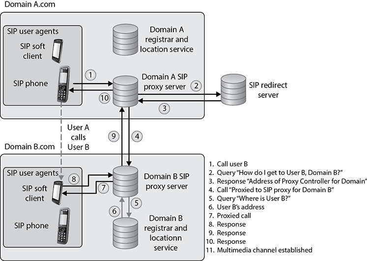
The SIP architecture consists of three different types of servers, which play an integral role in the entire communication process of the VoIP system. These servers are the proxy server, the registrar server, and the redirect server. The proxy server is used to relay packets within a network between the UACs and the UAS. It also forwards requests generated by callers to their respective recipients. Proxy servers are also generally used for name mapping, which allows the proxy server to interlink an external SIP system to an internal SIP client.
The registrar server keeps a centralized record of the updated locations of all the users on the network. These addresses are stored on a location server. The redirect server allows SIP devices to retain their SIP identities despite changes in their geographic location. This allows a device to remain accessible when its location is physically changed and hence while it moves through different networks. The use of redirect servers allows clients to remain within reach while they move through numerous network coverage zones. This configuration is generally known as an intraorganizational configuration. Intraorganizational routing enables SIP traffic to be routed within a VoIP network without being transmitted over the PSTN or external network.
Skype is a popular Internet telephony application that uses a peer-to-peer communication model rather than the traditional client/server approach of VoIP systems. The Skype network does not rely on centralized servers to maintain its user directories. Instead, user records are maintained across distributed member nodes. This is the reason the network can quickly accommodate user surges without having to rely on expensive central infrastructure and computing resources.
IP Telephony Issues
VoIP’s integration with the TCP/IP protocol has brought about immense security challenges because it allows malicious users to bring their TCP/IP experience into this relatively new platform, where they can probe for flaws in both the architecture and the VoIP systems. Also involved are the traditional security issues associated with networks, such as unauthorized access, exploitation of communication protocols, and the spreading of malware. The promise of financial benefit derived from stolen call time is a strong incentive for most attackers, as we mentioned in the section on PBXs earlier in this chapter. In short, the VoIP telephony network faces all the flaws that traditional computer networks have faced. Moreover, VoIP devices follow architectures similar to traditional computers—that is, they use operating systems, communicate through Internet protocols, and provide a combination of services and applications.
SIP-based signaling suffers from the lack of encrypted call channels and authentication of control signals. Attackers can tap into the SIP server and client communication to sniff out login IDs, passwords/PINs, and phone numbers. Once an attacker gets a hold of such information, he can use it to place unauthorized calls on the network. Toll fraud is considered to be the most significant threat that VoIP networks face. VoIP network implementations will need to ensure that VoIP–PSTN gateways are secure from intrusions to prevent these instances of fraud.
Attackers can also masquerade identities by redirecting SIP control packets from a caller to a forged destination to mislead the caller into communicating with an unintended end system. Like in any networked system, VoIP devices are also vulnerable to DoS attacks. Just as attackers would flood TCP servers with SYN packets on an IP network to exhaust a device’s resources, attackers can flood RTP servers with call requests in order to overwhelm its processing capabilities. Attackers have also been known to connect laptops simulating IP phones to the Ethernet interfaces that IP phones use. These systems can then be used to carry out intrusions and DoS attacks. In addition to these circumstances, if attackers are able to intercept voice packets, they may eavesdrop onto ongoing conversations. Attackers can also intercept RTP packets containing the media stream of a communication session to inject arbitrary audio/video data that may be a cause of annoyance to the actual participants.
Attackers can also impersonate a server and issue commands such as BYE, CHECKSYNC, and RESET to VoIP clients. The BYE command causes VoIP devices to close down while in a conversation, the CHECKSYNC command can be used to reboot VoIP terminals, and the RESET command causes the server to reset and reestablish the connection, which takes considerable time.
NOTE Recently, a new variant to traditional e-mail spam has emerged on VoIP networks, commonly known as SPIT (Spam over Internet Telephony). SPIT causes loss of VoIP bandwidth and is a time-wasting nuisance for the people on the attacked network. Because SPIT cannot be deleted like spam on first sight, the victim has to go through the entire message. SPIT is also a major cause of overloaded voicemail servers.
Combating VoIP security threats requires a well-thought-out infrastructure implementation plan. With the convergence of traditional and VoIP networks, balancing security while maintaining unconstrained traffic flow is crucial. The use of authorization on the network is an important step in limiting the possibilities of rogue and unauthorized entities on the network. Authorization of individual IP terminals ensures that only prelisted devices are allowed to access the network. Although not absolutely foolproof, this method is a first layer of defense in preventing possible rogue devices from connecting and flooding the network with illicit packets. In addition to this preliminary measure, it is essential for two communicating VoIP devices to be able to authenticate their identities. Device identification may occur on the basis of fixed hardware identification parameters, such as MAC addresses or other “soft” codes that may be assigned by servers.
The use of secure cryptographic protocols such as TLS ensures that all SIP packets are conveyed within an encrypted and secure tunnel. The use of TLS can provide a secure channel for VoIP client/server communication and prevents the possibility of eavesdropping and packet manipulation.
Remote Access
Remote access covers several technologies that enable remote and home users to connect to networks that will grant them access to resources needed for them to perform their tasks. Most of the time, these users must first gain access to the Internet through an ISP, which sets up a connection to the destination network.
For many corporations, remote access is a necessity because it enables users to access centralized network resources; it reduces networking costs by using the Internet as the access medium instead of expensive dedicated lines; and it extends the workplace for employees to their home computers, laptops, or mobile devices. Remote access can streamline access to resources and information through Internet connections and provides a competitive advantage by letting partners, suppliers, and customers have closely controlled links. The types of remote access methods we will cover next are dial-up connections, ISDN, cable modems, DSL, and VPNs.
Dial-up Connections
Since almost every house and office had a telephone line running to it already, the first type of remote access technology that was used took advantage of this in-place infrastructure. Modems were added to computers that needed to communicate with other computers over telecommunication lines.
Each telephone line is made up of UTP copper wires and has an available analog carrier signal and frequency range to move voice data back and forth. A modem (modulator-demodulator) is a device that modulates an outgoing digital signal into an analog signal that will be carried over an analog carrier, and demodulates the incoming analog signal into digital signals that can be processed by a computer.
While the individual computers had built-in modems to allow for Internet connectivity, organizations commonly had a pool of modems to allow for remote access into and out of their networks. In some cases the modems were installed on individual servers here and there throughout the network or they were centrally located and managed. Most companies did not properly enforce access control through these modem connections, and they served as easy entry points for attackers. Attackers used programs that carried out war dialing to identify modems that could be compromised. The attackers fed a large bank of phone numbers into the war-dialing tools, which in turn called each number. If a person answered the phone, the war dialer documented that the number was not connected to a computer system and dropped it from its list. If a fax machine answered, it did the same thing. If a modem answered, the war dialer would send signals and attempt to set up a connection between the attacker’s system and the target system. If it was successful, the attacker then had direct access to the network.
Most burglars are not going to break into a house through the front door, because there are commonly weaker points of entry that can be more easily compromised (back doors, windows, etc.). Hackers usually try to find “side doors” into a network instead of boldly trying to hack through a fortified firewall. In many environments, remote access points are not as well protected as the more traditional network access points. Attackers know this and take advantage of these situations.
CAUTION Antiquated as they may seem, many organizations have modems enabled that the network staff is unaware of. Therefore, it is important to search for them to ensure no unauthorized modems are attached and operational.
Like most telecommunication connections, dial-up connections take place over PPP, which has authentication capabilities. Authentication should be enabled for the PPP connections, but another layer of authentication should be in place before users are allowed access to network resources. We will cover access control in Chapter 5.
If you find yourself using modems, some of the security measures that you should put in place for dial-up connections include
• Configure the remote access server to call back the initiating phone number to ensure it is a valid and approved number.
• Disable or remove modems if not in use.
• Consolidate all modems into one location and manage them centrally, if possible.
• Implement use of two-factor authentication, VPNs, and personal firewalls for remote access connections.
While dial-up connections using modems still exist in some locations, this type of remote access has been mainly replaced with technologies that can digitize telecommunication connections.
ISDN
Integrated Services Digital Network (ISDN) is a technology provided by telephone companies and ISPs. This technology, and the necessary equipment, enables data, voice, and other types of traffic to travel over a medium in a digital manner previously used only for analog voice transmission. Telephone companies went all digital many years ago, except for the local loops, which consist of the copper wires that connect houses and businesses to their carrier provider’s central offices. These central offices contain the telephone company’s switching equipment, and it is here the analog-to-digital transformation takes place. However, the local loop is almost always analog, and is therefore slower. ISDN was developed to replace the aging telephone analog systems, but it has yet to catch on to the level expected.
ISDN uses the same wires and transmission medium used by analog dial-up technologies, but it works in a digital fashion. If a computer uses a modem to communicate with an ISP, the modem converts the data from digital to analog to be transmitted over the phone line. If that same computer was configured and had the necessary equipment to utilize ISDN, it would not need to convert the data from digital to analog, but would keep it in a digital form. This, of course, means the receiving end would also require the necessary equipment to receive and interpret this type of communication properly. Communicating in a purely digital form provides higher bit rates that can be sent more economically.
ISDN is a set of telecommunications services that can be used over public and private telecommunications networks. It provides a digital, point-to-point, circuit-switched medium and establishes a circuit between the two communicating devices. An ISDN connection can be used for anything a modem can be used for, but it provides more functionality and higher bandwidth. This digital service can provide bandwidth on an as-needed basis and can be used for LAN-to-LAN on-demand connectivity, instead of using an expensive dedicated link.
Analog telecommunication signals use a full channel for communication, but ISDN can break up this channel into multiple channels to move various types of data, and provide full-duplex communication and a higher level of control and error handling. ISDN provides two basic services: Basic Rate Interface (BRI) and Primary Rate Interface (PRI).
BRI has two B channels that enable data to be transferred and one D channel that provides for call setup, connection management, error control, caller ID, and more. The bandwidth available with BRI is 144 Kbps, and BRI service is aimed at small office and home office. The D channel provides for a quicker call setup and process in making a connection compared to dial-up connections. An ISDN connection may require a setup connection time of only 2 to 5 seconds, whereas a modem may require a timeframe of 45 to 90 seconds. This D channel is an out-of-band communication link between the local loop equipment and the user’s system. It is considered “out-of-band” because the control data is not mixed in with the user communication data. This makes it more difficult for a would-be defrauder to send bogus instructions back to the service provider’s equipment in hopes of causing a DoS, obtaining services not paid for, or conducting some other type of destructive behavior.
PRI has 23 B channels and one D channel, and is more commonly used in corporations. The total bandwidth is equivalent to a T1, which is 1.544 Mbps.
ISDN is not usually the primary telecommunications connection for companies, but it can be used as a backup in case the primary connection goes down. A company can also choose to implement dial-on-demand routing (DDR), which can work over ISDN. DDR allows a company to send WAN data over its existing telephone lines and use the public-switched telephone network (PSTN) as a temporary type of WAN link. It is usually implemented by companies that send out only a small amount of WAN traffic and is a much cheaper solution than a real WAN implementation. The connection activates when it is needed and then idles out.
DSL
Digital subscriber line (DSL) is another type of high-speed connection technology used to connect a home or business to the service provider’s central office. It can provide 6 to 30 times higher bandwidth speeds than ISDN and analog technologies. It uses existing phone lines and provides a 24-hour connection to the Internet at rates of up to 52 Mbps. This does indeed sound better than sliced bread, but only certain people can get this service because you have to be within a 2.5-mile radius of the DSL service provider’s equipment. As the distance between a residence and the central office increases, the transmission rates for DSL decrease.
DSL provides faster transmission rates than an analog dial-up connection because it uses all of the available frequencies available on a voice-grade UTP line. When you call someone, your voice data travels down this UTP line and the service provider “cleans up” the transmission by removing the high and low frequencies. Humans do not use these frequencies when they talk, so if there is anything on these frequencies, it is considered line noise and thus removed. So in reality, the available bandwidth of the line that goes from your house to the telephone company’s central office is artificially reduced. When DSL is used, this does not take place, and therefore the high and low frequencies can be used for data transmission.
DSL offers several types of services. With symmetric services, traffic flows at the same speed upstream and downstream (to and from the Internet or destination). With asymmetric services, the downstream speed is much higher than the upstream speed. In most situations, an asymmetric connection is fine for residential users because they usually download items from the Web much more often than they upload data.
Cable Modems
The cable television companies have been delivering television services to homes for years, and then they started delivering data transmission services for users who have cable modems and want to connect to the Internet at high speeds.
Cable modems provide high-speed access to the Internet through existing cable coaxial and fiber lines. The cable modem provides upstream and downstream conversions.
Coaxial and fiber cables are used to deliver hundreds of television stations to users, and one or more of the channels on these lines are dedicated to carrying data. The bandwidth is shared between users in a local area; therefore, it will not always stay at a static rate. So, for example, if Mike attempts to download a program from the Internet at 5:30 p.m., he most likely will have a much slower connection than if he had attempted it at 10:00 A.M., because many people come home from work and hit the Internet at the same time. As more people access the Internet within his local area, Mike’s Internet access performance drops.
Most cable providers comply with Data-Over-Cable Service Interface Specifications (DOCSIS), which is an international telecommunications standard that allows for the addition of high-speed data transfer to an existing cable TV (CATV) system. DOCSIS includes MAC layer security services in its Baseline Privacy Interface/Security (BPI/SEC) specifications. This protects individual user traffic by encrypting the data as it travels over the provider’s infrastructure.
Sharing the same medium brings up a slew of security concerns, because users with network sniffers can easily view their neighbors’ traffic and data as both travel to and from the Internet. Many cable companies are now encrypting the data that goes back and forth over shared lines through a type of data link encryption.
VPN
A virtual private network (VPN) is a secure, private connection through an untrusted network, as shown in Figure 4-75. It is a private connection because the encryption and tunneling protocols are used to ensure the confidentiality and integrity of the data in transit. It is important to remember that VPN technology requires a tunnel to work and it assumes encryption.
We need VPNs because we send so much confidential information from system to system and network to network. The information can be credentials, bank account data, Social Security numbers, medical information, or any other type of data we do not want to share with the world. The demand for securing data transfers has increased over the years, and as our networks have increased in complexity, so have our VPN solutions.

Figure 4-75 A VPN provides a virtual dedicated link between two entities across a public network.
Point-To-Point Tunneling Protocol
For many years the de facto standard VPN software was point-to-point tunneling protocol (PPTP), which was made most popular when Microsoft included it in its Windows products. Since most Internet-based communication first started over telecommunication links, the industry needed a way to secure PPP connections. The original goal of PPTP was to provide a way to tunnel PPP connections through an IP network, but most implementations included security features also since protection was becoming an important requirement for network transmissions at that time.
PPTP uses Generic Routing Encapsulation (GRE) and TCP to encapsulate PPP packets and extend a PPP connection through an IP network, as shown in Figure 4-76. In Microsoft implementations, the tunneled PPP traffic can be authenticated with PAP, CHAP, MS-CHAP, or EAP-TLS and the PPP payload is encrypted using Microsoft Point-to-Point Encryption (MPPE). Other vendors have integrated PPTP functionality in their products for interoperability purposes.
The first security technologies that hit the market commonly have security issues and drawbacks identified after their release, and PPTP was no different. The earlier authentication methods that were used with PPTP had some inherent vulnerabilities, which allowed an attacker to easily uncover password values. MPPE also used the symmetric algorithm RC4 in a way that allowed data to be modified in an unauthorized manner, and through the use of certain attack tools, the encryption keys could be uncovered. Later implementations of PPTP addressed these issues, but the protocol still has some limitations that should be understood. For example, PPTP cannot support multiple connections over one VPN tunnel, which means that it can be used for system-to-system communication but not gateway-to-gateway connections that must support many user connections simultaneously. PPTP relies on PPP functionality for a majority of its security features, and because it never became an actual industry standard, incompatibilities through different vendor implementations exist.

Figure 4-76 PPTP extends PPP connections over IP networks.
Layer 2 Tunneling Protocol
Another VPN solution was developed that combines the features of PPTP and Cisco’s Layer 2 Forwarding (L2F) protocol. Layer 2 Tunneling Protocol (L2TP) tunnels PPP traffic over various network types (IP, ATM, X.25, etc.); thus, it is not just restricted to IP networks as PPTP is. PPTP and L2TP have very similar focuses, which is to get PPP traffic to an end point that is connected to some type of network that does not understand PPP. Like PPTP, L2TP does not actually provide much protection for the PPP traffic it is moving around, but it integrates with protocols that do provide security features. L2TP inherits PPP authentication and integrates with IPSec to provide confidentiality, integrity, and potentially another layer of authentication.
NOTE PPP provides user authentication through PAP, CHAP, or EAP-TLS, whereas IPSec provides system authentication.
It can get confusing when several protocols are involved with various levels of encapsulation, but if you do not understand how they work together, you cannot identify if certain traffic links lack security. To figure out if you understand how these protocols work together and why, ask yourself these questions:
1. If the Internet is an IP-based network, why do we even need PPP?
2. If PPTP and L2TP do not actually secure data themselves, then why do they exist?
3. If PPTP and L2TP basically do the same thing, why choose L2TP over PPTP?
4. If a connection is using IP, PPP, and L2TP, where does IPSec come into play?
Let’s go through the answers together. Let’s say that you are a remote user and work from your home office. You do not have a dedicated link from your house to your company’s network; instead, your traffic needs to go through the Internet to be able to communicate with the corporate network. The line between your house and your ISP is a point-to-point telecommunications link, one point being your home router and the other point being the ISP’s switch, as shown in Figure 4-77. Point-to-point telecommunication devices do not understand IP, so your router has to encapsulate your traffic in a protocol the ISP’s device will understand—PPP. Now your traffic is not headed toward some website on the Internet; instead, it has a target of your company’s corporate network. This means that your traffic has to be “carried through” the Internet to its ultimate destination through a tunnel. The Internet does not understand PPP, so your PPP traffic has to be encapsulated with a protocol that can work on the Internet and create the needed tunnel, as in PPTP or L2TP. If the connection between your ISP and the corporate network will not happen over the regular Internet (IP-based network), but instead over a WAN-based connection (ATM, frame relay), then L2TP has to be used for this PPP tunnel because PPTP cannot travel over non-IP networks.
So your IP packets are wrapped up in PPP, which are then wrapped up in L2TP. But you still have no encryption involved, so your data is actually not protected. This is where IPSec comes in. IPSec is used to encrypt the data that will pass through the L2TP tunnel. Once your traffic gets to the corporate network’s perimeter device, it will decrypt the packets, take off the L2TP and PPP headers, add the necessary Ethernet headers, and send these packets to their ultimate destination.

Figure 4-77 IP, PPP, L2TP, and IPSec can work together.
So here are the answers to our questions:
1. If the Internet is an IP-based network, why do we even need PPP?
Answer: The point-to-point line devices that connect individual systems to the Internet do not understand IP, so the traffic that travels over these links has to be encapsulated in PPP.
2. If PPTP and L2TP do not actually secure data themselves, then why do they exist?
Answer: They extend PPP connections by providing a tunnel through networks that do not understand PPP.
3. If PPTP and L2TP basically do the same thing, why choose L2TP over PPTP?
Answer: PPTP only works over IP-based networks. L2TP works over IP-based and WAN-based (ATM, frame relay) connections. If a PPP connection needs to be extended over a WAN-based connection, L2TP must be used.
4. If a connection is using IP, PPP, and L2TP, where does IPSec come into play?
Answer: IPSec provides the encryption, data integrity, and system-based authentication.
So here is another question. Does all of this PPP, PPTP, L2TP, and IPSec encapsulation have to happen for every single VPN used on the Internet? No, only when connections over point-to-point connections are involved. When two gateway routers are connected over the Internet and provide VPN functionality, they only have to use IPSec.
Internet Protocol Security
IPSec is a suite of protocols that was developed to specifically protect IP traffic. IPv4 does not have any integrated security, so IPSec was developed to “bolt onto” IP and secure the data the protocol transmits. Where PPTP and L2TP work at the data link layer, IPSec works at the network layer of the OSI model.
The main protocols that make up the IPSec suite and their basic functionality are as follows:
• Authentication Header (AH) Provides data integrity, data-origin authentication, and protection from replay attacks
• Encapsulating Security Payload (ESP) Provides confidentiality, data-origin authentication, and data integrity
• Internet Security Association and Key Management Protocol (ISAKMP) Provides a framework for security association creation and key exchange
• Internet Key Exchange (IKE) Provides authenticated keying material for use with ISAKMP
AH and ESP can be used separately or together in an IPSec VPN configuration. The AH protocols can provide data-origin authentication (system authentication) and protection from unauthorized modification, but do not provide encryption capabilities. If the VPN needs to provide confidentiality, then ESP has to be enabled and configured properly.
When two routers need to set up an IPSec VPN connection, they have a list of security attributes that need to be agreed upon through handshaking processes. The two routers have to agree upon algorithms, keying material, protocol types, and modes of use, which will all be used to protect the data that is transmitted between them.
Let’s say that you and Juan are routers that need to protect the data you will pass back and forth to each other. Juan send’s you a list of items that you will use to process the packets he sends to you. His list contains AES-128, SHA-1, and ESP tunnel mode. You take these parameters and store them in a security association (SA). When Juan sends you packets one hour later, you will go to this SA and follow these parameters so that you know how to process this traffic. You know what algorithm to use to verify the integrity of the packets, the algorithm to use to decrypt the packets, and which protocol to activate and in what mode. Figure 4-78 illustrates how SAs are used for inbound and outbound traffic.
NOTE The U.S. National Security Agency (NSA) uses a protocol encryptor that is based upon IPSec. A HAIPE (High Assurance Internet Protocol Encryptor) is a Type 1 encryption device that is based on IPSec with additional restrictions, enhancements, and capabilities. A HAIPE is typically a secure gateway that allows two enclaves to exchange data over an untrusted or lower-classification network. Since this technology works at the network layer, secure end-to-end connectivity can take place in heterogeneous environments. This technology has largely replaced link layer encryption technology implementations.

Figure 4-78 IPSec uses security associations to store VPN parameters.
Transport Layer Security VPN
A newer VPN technology is Transport Layer Security (TLS), which works at even higher layers in the OSI model than the previously covered VPN protocols. TLS, which we discuss in detail later in this chapter, works at the session layer of the network stack and is used mainly to protect HTTP traffic. TLS capabilities are already embedded into most web browsers, so the deployment and interoperability issues are minimal.
IPSec can be configured to provide transport adjacency, which just means that more than one security protocol (ESP and AH) is used in a VPN tunnel. IPSec can also be configured to provide iterated tunneling, in which an IPSec tunnel is tunneled through another IPSec tunnel, as shown in the following diagram. Iterated tunneling would be used if the traffic needed different levels of protection at different junctions of its path. For example, if the IPSec tunnel started from an internal host and terminated at an internal border router, this may not require encryption, so only the AH protocol would be used. But when that data travels from that border router throughout the Internet to another network, then the data requires more protection. So the first packets travel through a semisecure tunnel until they get ready to hit the Internet and then they go through a very secure second tunnel.

The most common implementation types of TLS VPN are as follows:
• TLS portal VPN An individual uses a single standard TLS connection to a website to securely access multiple network services. The website accessed is typically called a portal because it is a single location that provides access to other resources. The remote user accesses the TLS VPN gateway using a web browser, is authenticated, and is then presented with a web page that acts as the portal to the other services.
• TLS tunnel VPN An individual uses a web browser to securely access multiple network services, including applications and protocols that are not web-based, through a TLS tunnel. This commonly requires custom programming to allow the services to be accessible through a web-based connection.
Since TLS VPNs are closer to the application layer, they can provide more granular access control and security features compared to the other VPN solutions. But since they are dependent on the application layer protocol, there are a smaller number of traffic types that can be protected through this VPN type.
One VPN solution is not necessarily better than the other; they just have their own focused purposes:
• PPTP is used when a PPP connection needs to be extended through an IP-based network.
• L2TP is used when a PPP connection needs to be extended through a non–
IP-based network.
• IPSec is used to protect IP-based traffic and is commonly used in gateway-to-gateway connections.
• TLS VPN is used when a specific application layer traffic type needs protection.
Again, what can be used for good can also be used for evil. Attackers commonly encrypt their attack traffic so that countermeasures we put into place to analyze traffic for suspicious activity are not effective. Attackers can use TLS or PPTP to encrypt malicious traffic as it traverses the network. When an attacker compromises and opens up a back door on a system, she will commonly encrypt the traffic that will then go between her system and the compromised system. It is important to configure security network devices to only allow approved encrypted channels.
Authentication Protocols
Password Authentication Protocol (PAP) is used by remote users to authenticate over PPP connections. It provides identification and authentication of the user who is attempting to access a network from a remote system. This protocol requires a user to enter a password before being authenticated. The password and the username credentials are sent over the network to the authentication server after a connection has been established via PPP. The authentication server has a database of user credentials that are compared to the supplied credentials to authenticate users.
PAP is one of the least secure authentication methods because the credentials are sent in cleartext, which renders them easy to capture by network sniffers. Although it is not recommended, some systems revert to PAP if they cannot agree on any other authentication protocol. During the handshake process of a connection, the two entities negotiate how authentication is going to take place, what connection parameters to use, the speed of data flow, and other factors. Both entities will try to negotiate and agree upon the most secure method of authentication; they may start with EAP, and if one computer does not have EAP capabilities, they will try to agree upon CHAP; if one of the computers does not have CHAP capabilities, they may be forced to use PAP. If this type of authentication is unacceptable, the administrator will configure the remote access server (RAS) to accept only CHAP authentication and higher, and PAP cannot be used at all.
Challenge Handshake Authentication Protocol (CHAP) addresses some of the vulnerabilities found in PAP. It uses a challenge/response mechanism to authenticate the user instead of having the user send a password over the wire. When a user wants to establish a PPP connection and both ends have agreed that CHAP will be used for authentication purposes, the user’s computer sends the authentication server a logon request. The server sends the user a challenge (nonce), which is a random value. This challenge is encrypted with the use of a predefined password as an encryption key, and the encrypted challenge value is returned to the server. The authentication server also uses the predefined password as an encryption key and decrypts the challenge value, comparing it to the original value sent. If the two results are the same, the authentication server deduces that the user must have entered the correct password, and authentication is granted. The steps that take place in CHAP are depicted in Figure 4-79.

Figure 4-79 CHAP uses a challenge/response mechanism instead of having the user send the password over the wire.
EXAM TIP MS-CHAP is Microsoft’s version of CHAP and provides mutual authentication functionality. It has two versions, which are incompatible with each other.
PAP is vulnerable to sniffing because it sends the password and data in plaintext, but it is also vulnerable to man-in-the-middle attacks. CHAP is not vulnerable to man-in-the-middle attacks because it continues this challenge/response activity throughout the connection to ensure the authentication server is still communicating with a user who holds the necessary credentials.
Extensible Authentication Protocol (EAP) is also supported by PPP. Actually, EAP is not a specific authentication protocol as are PAP and CHAP. Instead, it provides a framework to enable many types of authentication techniques to be used when establishing network connections. As the name states, it extends the authentication possibilities from the norm (PAP and CHAP) to other methods, such as one-time passwords, token cards, biometrics, Kerberos, digital certificates, and future mechanisms. So when a user connects to an authentication server and both have EAP capabilities, they can negotiate between a longer list of possible authentication methods.
NOTE EAP has been defined for use with a variety of technologies and protocols, including PPP, PPTP, L2TP, IEEE 802 wired networks, and wireless technologies such as 802.11 and 802.16.
There are many different variants of EAP, as shown in Table 4-16, because EAP is an extensible framework that can be morphed for different environments and needs.

Table 4-16 EAP Variants
Network Encryption
At this point in our discussion, we have touched on every major technology relevant to modern networks. Along the way, as we paused to consider vulnerabilities and controls, a recurring theme revolves around the use of encryption to protect the confidentiality and integrity of our data. Let us now take a look at three specific applications of encryption to protect our data communications in general and our e-mail and web traffic in particular.
Link Encryption vs. End-to-End Encryption
In each of the networking technologies discussed in this chapter, encryption can be performed at different levels, each with different types of protection and implications. Two general modes of encryption implementation are link encryption and end-to-end encryption. Link encryption encrypts all the data along a specific communication path, as in a satellite link, T3 line, or telephone circuit. Not only is the user information encrypted, but the header, trailers, addresses, and routing data that are part of the packets are also encrypted. The only traffic not encrypted in this technology is the data link control messaging information, which includes instructions and parameters that the different link devices use to synchronize communication methods. Link encryption provides protection against packet sniffers and eavesdroppers. In end-to-end encryption, the headers, addresses, routing information, and trailer information are not encrypted, enabling attackers to learn more about a captured packet and where it is headed.
Link encryption, which is sometimes called online encryption, is usually provided by service providers and is incorporated into network protocols. All of the information is encrypted, and the packets must be decrypted at each hop so the router, or other intermediate device, knows where to send the packet next. The router must decrypt the header portion of the packet, read the routing and address information within the header, and then re-encrypt it and send it on its way.
With end-to-end encryption, the packets do not need to be decrypted and then encrypted again at each hop because the headers and trailers are not encrypted. The devices in between the origin and destination just read the necessary routing information and pass the packets on their way.
End-to-end encryption is usually initiated by the user of the originating computer. It provides more flexibility for the user to be able to determine whether or not certain messages will get encrypted. It is called “end-to-end encryption” because the message stays encrypted from one end of its journey to the other. Link encryption has to decrypt the packets at every device between the two ends.
Link encryption occurs at the data link and physical layers, as depicted in Figure 4-80. Hardware encryption devices interface with the physical layer and encrypt all data that passes through them. Because no part of the data is available to an attacker, the attacker cannot learn basic information about how data flows through the environment. This is referred to as traffic-flow security.
NOTE A hop is a device that helps a packet reach its destination. It is usually a router that looks at the packet address to determine where the packet needs to go next. Packets usually go through many hops between the sending and receiving computers.
Advantages of end-to-end encryption include the following:
• It provides more flexibility to the user in choosing what gets encrypted and how.
• Higher granularity of functionality is available because each application or user can choose specific configurations.
• Each hop device on the network does not need to have a key to decrypt each packet.

Figure 4-80 Link and end-to-end encryption happen at different OSI layers.
Disadvantages of end-to-end encryption include the following:
• Headers, addresses, and routing information are not encrypted, and therefore not protected.
Advantages of link encryption include the following:
• All data is encrypted, including headers, addresses, and routing information.
• Users do not need to do anything to initiate it. It works at a lower layer in the OSI model.
Disadvantages of link encryption include the following:
• Key distribution and management are more complex because each hop device must receive a key, and when the keys change, each must be updated.
• Packets are decrypted at each hop; thus, more points of vulnerability exist.
E-mail Encryption Standards
Like other types of technologies, cryptography has industry standards and de facto standards. Standards are necessary because they help ensure interoperability among vendor products. The existence of standards for a certain technology usually means that it has been under heavy scrutiny and has been properly tested and accepted by many similar technology communities. A company still needs to decide what type of standard to follow and what type of technology to implement.
A company needs to evaluate the functionality of the technology and perform a cost-benefit analysis on the competing products within the chosen standards. For a cryptography implementation, the company would need to decide what must be protected by encryption, whether digital signatures are necessary, how key management should take place, what types of resources are available to implement and maintain the technology, and what the overall cost will amount to.
If a company only needs to encrypt some e-mail messages here and there, then Pretty Good Privacy (PGP) may be the best choice. If the company wants all data encrypted as it goes throughout the network and to sister companies, then a link encryption implementation may be the best choice. If a company wants to implement a single sign-on environment where users need to authenticate to use different services and functionality throughout the network, then implementing a PKI or Kerberos might serve it best. To make the most informed decision, the network administrators should understand each type of technology and standard, and should research and test each competing product within the chosen technology before making the final purchase. Cryptography, including how to implement and maintain it, can be a complicated subject. Doing homework versus buying into buzzwords and flashy products might help a company reduce its headaches down the road.
The following sections briefly describe some of the most popular e-mail standards in use.
Multipurpose Internet Mail Extensions
Multipurpose Internet Mail Extensions (MIME) is a technical specification indicating how multimedia data and e-mail binary attachments are to be transferred. The Internet has mail standards that dictate how mail is to be formatted, encapsulated, transmitted, and opened. If a message or document contains a binary attachment, MIME dictates how that portion of the message should be handled.
When an attachment contains an audio clip, graphic, or some other type of multimedia component, the e-mail client will send the file with a header that describes the file type. For example, the header might indicate that the MIME type is Image and that the subtype is jpeg. Although this will be in the header, many times, systems also use the file’s extension to identify the MIME type. So, in the preceding example, the file’s name might be stuff.jpeg. The user’s system will see the extension .jpeg, or will see the data in the header field, and look in its association list to see what program it needs to initialize to open this particular file. If the system has JPEG files associated with the Explorer application, then Explorer will open and present the picture to the user.
Sometimes systems either do not have an association for a specific file type or do not have the helper program necessary to review and use the contents of the file. When a file has an unassociated icon assigned to it, it might require the user to choose the Open With command and choose an application in the list to associate this file with that program. So when the user double-clicks that file, the associated program will initialize and present the file. If the system does not have the necessary program, the website might offer the necessary helper program, like Acrobat or an audio program that plays WAV files.
MIME is a specification that dictates how certain file types should be transmitted and handled. This specification has several types and subtypes, enables different computers to exchange data in varying formats, and provides a standardized way of presenting the data. So if Sean views a funny picture that is in GIF format, he can be sure that when he sends it to Debbie, it will look exactly the same.
Secure MIME (S/MIME) is a standard for encrypting and digitally signing e-mail and for providing secure data transmissions. S/MIME extends the MIME standard by allowing for the encryption of e-mail and attachments. The encryption and hashing algorithms can be specified by the user of the mail application, instead of having it dictated to them. S/MIME follows the Public Key Cryptography Standards (PKCS). S/MIME provides confidentiality through encryption algorithms, integrity through hashing algorithms, authentication through the use of X.509 public key certificates, and nonrepudiation through cryptographically signed message digests.
Pretty Good Privacy
Pretty Good Privacy (PGP) was designed by Phil Zimmerman as a freeware e-mail security program and was released in 1991. It was the first widespread public key encryption program. PGP is a complete cryptosystem that uses cryptographic protection to protect e-mail and files. It can use RSA public key encryption for key management and use the IDEA symmetric cipher for bulk encryption of data, although the user has the option of picking different types of algorithms for these functions. PGP can provide confidentiality by using the IDEA encryption algorithm, integrity by using the MD5 hashing algorithm, authentication by using public key certificates, and nonrepudiation by using cryptographically signed messages. PGP uses its own type of digital certificates rather than what is used in PKI, but they both have similar purposes.
The user’s private key is generated and encrypted when the application asks the user to randomly type on her keyboard for a specific amount of time. Instead of using passwords, PGP uses passphrases. The passphrase is used to encrypt the user’s private key that is stored on her hard drive.
PGP does not use a hierarchy of CAs, or any type of formal trust certificates, but instead relies on a “web of trust” in its key management approach. Each user generates and distributes his or her public key, and users sign each other’s public keys, which creates a community of users who trust each other. This is different from the CA approach, where no one trusts each other; they only trust the CA. For example, if Mark and Joe want to communicate using PGP, Mark can give his public key to Joe. Joe signs Mark’s key and keeps a copy for himself. Then, Joe gives a copy of his public key to Mark so they can start communicating securely. Later, Mark would like to communicate with Sally, but Sally does not know Mark and does not know if she can trust him. Mark sends Sally his public key, which has been signed by Joe. Sally has Joe’s public key, because they have communicated before, and she trusts Joe. Because Joe signed Mark’s public key, Sally now also trusts Mark and sends her public key to him and begins communicating with him.
So, basically, PGP is a system of “I don’t know you, but my buddy Joe says you are an all right guy, so I will trust you on Joe’s word.”
Each user keeps in a file, referred to as a key ring, a collection of public keys he has received from other users. Each key in that ring has a parameter that indicates the level of trust assigned to that user and the validity of that particular key. If Steve has known Liz for many years and trusts her, he might have a higher level of trust indicated on her stored public key than on Tom’s, whom he does not trust much at all. There is also a field indicating who can sign other keys within Steve’s realm of trust. If Steve receives a key from someone he doesn’t know, like Kevin, and the key is signed by Liz, he can look at the field that pertains to whom he trusts to sign other people’s keys. If the field indicates that Steve trusts Liz enough to sign another person’s key, Steve will accept Kevin’s key and communicate with him because Liz is vouching for him. However, if Steve receives a key from Kevin and it is signed by untrustworthy Tom, Steve might choose to not trust Kevin and not communicate with him.
These fields are available for updating and alteration. If one day Steve really gets to know Tom and finds out he is okay after all, he can modify these parameters within PGP and give Tom more trust when it comes to cryptography and secure communication.
Because the web of trust does not have a central leader, such as a CA, certain standardized functionality is harder to accomplish. If Steve were to lose his private key, he would need to notify everyone else trusting his public key that it should no longer be trusted. In a PKI, Steve would only need to notify the CA, and anyone attempting to verify the validity of Steve’s public key would be told not to trust it upon looking at the most recently updated CRL. In the PGP world, this is not as centralized and organized. Steve can send out a key revocation certificate, but there is no guarantee it will reach each user’s key ring file.
PGP is a public domain software that uses public key cryptography. It has not been endorsed by the NSA, but because it is a great product and free for individuals to use, it has become somewhat of a de facto encryption standard on the Internet.
NOTE PGP is considered a cryptosystem because it has all the necessary components: symmetric key algorithms, asymmetric key algorithms, message digest algorithms, keys, protocols, and the necessary software components.
Internet Security
The Web is not the Internet. The Web runs on top of the Internet, in a sense. The Web is the collection of HTTP servers that holds and processes websites we see. The Internet is the collection of physical devices and communication protocols used to traverse these websites and interact with them. The websites look the way they do because their creators used a language that dictates the look, feel, and functionality of the page. Web browsers enable users to read web pages by enabling them to request and accept web pages via HTTP, and the user’s browser converts the language (HTML, DHTML, and XML) into a format that can be viewed on the monitor. The browser is the user’s window to the World Wide Web.
Browsers can understand a variety of protocols and have the capability to process many types of commands, but they do not understand them all. For those protocols or commands the user’s browser does not know how to process, the user can download and install a viewer or plug-in, a modular component of code that integrates itself into the system or browser. This is a quick and easy way to expand the functionality of the browser. However, this can cause serious security compromises, because the payload of the module can easily carry viruses and malicious software that users don’t discover until it’s too late.
Start with the Basics
Why do we connect to the Internet? At first, this seems a basic question, but as we dive deeper into the query, complexity creeps in. We connect to download MP3s, check e-mail, order security books, look at websites, communicate with friends, and perform various other tasks. But what are we really doing? We are using services provided by a computer’s protocols and software. The services may be file transfers provided by FTP, remote access provided by Telnet, Internet connectivity provided by HTTP, secure connections provided by TLS, and much, much more. Without these protocols, there would be no way to even connect to the Internet.
Management needs to decide what functionality employees should have pertaining to Internet use, and the administrator must implement these decisions by controlling services that can be used inside and outside the network. Services can be restricted in various ways, such as allowing certain services to only run on a particular system and to restrict access to that system; employing a secure version of a service; filtering the use of services; or blocking services altogether. These choices determine how secure the site will be and indicate what type of technology is needed to provide this type of protection.
Let’s go through many of the technologies and protocols that make up the World Wide Web.
HTTP TCP/IP is the protocol suite of the Internet, and HTTP is the protocol of the Web. HTTP sits on top of TCP/IP. When a user clicks a link on a web page with her mouse, her browser uses HTTP to send a request to the web server hosting that website. The web server finds the corresponding file to that link and sends it to the user via HTTP. So where is TCP/IP in all of this? TCP controls the handshaking and maintains the connection between the user and the server, and IP makes sure the file is routed properly throughout the Internet to get from the web server to the user. So, IP finds the way to get from A to Z, TCP makes sure the origin and destination are correct and that no packets are lost along the way, and, upon arrival at the destination, HTTP presents the payload, which is a web page.
HTTP is a stateless protocol, which means the client and web server make and break a connection for each operation. When a user requests to view a web page, that web server finds the requested web page, presents it to the user, and then terminates the connection. If the user requests a link within the newly received web page, a new connection must be set up, the request goes to the web server, and the web server sends the requested item and breaks the connection. The web server never “remembers” the users that ask for different web pages, because it would have to commit a lot of resources to the effort.
HTTP Secure HTTP Secure (HTTPS) is HTTP running over Secure Sockets Layer (SSL) or Transport Layer Security (TLS). Both of these technologies work to encrypt traffic originating at a higher layer in the OSI model. Though we will discuss SSL next (since it is still in use), you must keep in mind that this technology is now widely regarded as insecure and obsolete. The Internet Engineering Task Force formally deprecated it in June 2015. TLS should be used in its place.
Secure Sockets Layer Secure Sockets Layer (SSL) uses public key encryption and provides data encryption, server authentication, message integrity, and optional client authentication. When a client accesses a website, that website may have both secured and public portions. The secured portion would require the user to be authenticated in some fashion. When the client goes from a public page on the website to a secured page, the web server will start the necessary tasks to invoke SSL and protect this type of communication.
The server sends a message back to the client, indicating a secure session should be established, and the client in response sends its security parameters. The server compares those security parameters to its own until it finds a match. This is the handshaking phase. The server authenticates to the client by sending it a digital certificate, and if the client decides to trust the server, the process continues. The server can require the client to send over a digital certificate for mutual authentication, but that is rare.
The client generates a session key and encrypts it with the server’s public key. This encrypted key is sent to the web server, and they both use this symmetric key to encrypt the data they send back and forth. This is how the secure channel is established.
SSL keeps the communication path open until one of the parties requests to end the session. The session is usually ended when the client sends the server a FIN packet, which is an indication to close out the channel.
SSL requires an SSL-enabled server and browser. SSL provides security for the connection, but does not offer security for the data once received. This means the data is encrypted while being transmitted, but not after the data is received by a computer. So if a user sends bank account information to a financial institution via a connection protected by SSL, that communication path is protected, but the user must trust the financial institution that receives this information, because at this point, SSL’s job is done.
The user can verify that a connection is secure by looking at the URL to see that it includes https://. The user can also check for a padlock or key icon, depending on the browser type, which is shown at the bottom corner of the browser window.
In the protocol stack, SSL lies beneath the application layer and above the network layer. This ensures SSL is not limited to specific application protocols and can still use the communication transport standards of the Internet. Different books and technical resources place SSL at different layers of the OSI model, which may seem confusing at first. But the OSI model is a conceptual construct that attempts to describe the reality of networking. This is like trying to draw nice neat boxes around life—some things don’t fit perfectly and hang over the sides. SSL is actually made up of two protocols: one works at the lower end of the session layer, and the other works at the top of the transport layer. This is why one resource will state that SSL works at the session layer and another resource puts it in the transport layer. For the purposes of the CISSP exam, we’ll use the latter definition: the SSL protocol works at the transport layer.
Although SSL is almost always used with HTTP, it can also be used with other types of protocols. So if you see a common protocol that is followed by an S, that protocol is using SSL to encrypt its data. The final version of SSL was 3.0. SSL is considered insecure today.
Transport Layer Security SSL was developed by Netscape and is not an open-community protocol. This means the technology community cannot easily extend SSL to interoperate and expand in its functionality. If a protocol is proprietary in nature, as SSL is, the technology community cannot directly change its specifications and functionality. If the protocol is an open-community protocol, then its specifications can be modified by individuals within the community to expand what it can do and what technologies it can work with. So the open-community and standardized version of SSL is Transport Layer Security (TLS).
Until relatively recently, most people thought that there were very few differences between SSL 3.0 and TLS 1.0 (TLS is currently in version 1.3.). However, the Padding Oracle On Downgraded Legacy Encryption (POODLE) attack in 2014 was the death knell of SSL and demonstrated that TLS was superior security-wise. The key to the attack was to force SSL to downgrade its security, which was allowed for the sake of interoperability. Because TLS implements tighter controls and includes more modern (and more secure) hashing and encryption algorithms, it won the day and is now the standard.
TLS is commonly used when data needs to be encrypted while “in transit,” which means as the data is moving from one system to another system. Data must also be encrypted while “at rest,” which is when the data is stored. Encryption of data at rest can be accomplished by whole-disk encryption, PGP, or other types of software-based encryption.
Cookies Cookies are text files that a browser maintains on a user’s hard drive or memory segment. Cookies have different uses, and some are used for demographic and advertising information. As a user travels from site to site on the Internet, the sites could be writing data to the cookies stored on the user’s system. The sites can keep track of the user’s browsing and spending habits and the user’s specific customization for certain sites. For example, if Emily mainly goes to gardening sites on the Internet, those sites will most likely record this information and the types of items in which she shows most interest. Then, when Emily returns to one of the same or similar sites, it will retrieve her cookies, find she has shown interest in gardening books in the past, and present her with its line of gardening books. This increases the likelihood that Emily will purchase a book. This is a way of zeroing in on the right marketing tactics for the right person.
The servers at the website determine how cookies are actually used. When a user adds items to his shopping cart on a site, such data is usually added to a cookie. Then, when the user is ready to check out and pay for his items, all the data in this specific cookie is extracted and the totals are added.
As stated before, HTTP is a stateless protocol, meaning a web server has no memory of any prior connections. This is one reason to use cookies. They retain the memory between HTTP connections by saving prior connection data to the client’s computer.
For example, if you carry out your banking activities online, your bank’s web server keeps track of your activities through the use of cookies. When you first go to its site and are looking at public information, such as branch locations, hours of operation, and CD rates, no confidential information is being transferred back and forth. Once you make a request to access your bank account, the web server sets up an TLS connection and requires you to send credentials. Once you send your credentials and are authenticated, the server generates a cookie with your authentication and account information in it. The server sends it to your browser, which either saves it to your hard drive or keeps it in memory.
NOTE Some cookies are stored as text files on your hard drive. These files should not contain any sensitive information, such as account numbers and passwords. In most cases, cookies that contain sensitive information stay resident in memory and are not stored on the hard drive.
So, suppose you look at your checking account, do some work there, and then request to view your savings account information. The web server sends a request to see if you have been properly authenticated for this activity by checking your cookie.
Most online banking software also periodically requests your cookie to ensure no man-in-the-middle attacks are going on and that someone else has not hijacked the session.
It is also important to ensure that secure connections time out. This is why cookies have timestamps within them. If you have ever worked on a site that has an TLS connection set up for you and it required you to reauthenticate, the reason is that your session has been idle for a while and, instead of leaving a secure connection open, the web server software closed it out.
A majority of the data within a cookie is meaningless to any entities other than the servers at specific sites, but some cookies can contain usernames and passwords for different accounts on the Internet. The cookies that contain sensitive information should be encrypted by the server at the site that distributes them, but this does not always happen, and a nosy attacker could find this data on the user’s hard drive and attempt to use it for mischievous activity. Some people who live on the paranoid side of life do not allow cookies to be downloaded to their systems (which can be configured through browser security settings). Although this provides a high level of protection against different types of cookie abuse, it also reduces their functionality on the Internet. Some sites require cookies because there is specific data within the cookies that the site must utilize correctly in order to provide the user with the services she requested.
TIP Some third-party products can limit the type of cookies downloaded, hide the user’s identities as he travels from one site to the next, and mask the user’s e-mail addresses and the mail servers he uses if he is concerned about concealing his identity and his tracks.

Figure 4-81 SSH is used for remote terminal-like functionality.
Secure Shell Secure Shell (SSH) functions as a type of tunneling mechanism that provides terminal-like access to remote computers. SSH is a program and a protocol that can be used to log into another computer over a network. For example, the program can let Paul, who is on computer A, access computer B’s files, run applications on computer B, and retrieve files from computer B without ever physically touching that computer. SSH provides authentication and secure transmission over vulnerable channels like the Internet.
NOTE SSH can also be used for secure channels for file transfer and port redirection.
SSH should be used instead of Telnet, FTP, rlogin, rexec, or rsh, which provide the same type of functionality SSH offers but in a much less secure manner. SSH is a program and a set of protocols that work together to provide a secure tunnel between two computers. The two computers go through a handshaking process and exchange (via Diffie-Hellman) a session key that will be used during the session to encrypt and protect the data sent. The steps of an SSH connection are outlined in Figure 4-81.
Once the handshake takes place and a secure channel is established, the two computers have a pathway to exchange data with the assurance that the information will be encrypted and its integrity will be protected.

EXAM TIP (ISC)2 dropped network attacks from this domain in the April 2018 update. However, we feel it is important to briefly cover some of the more common adversarial techniques for completeness. You should not expect your exam to include the material covered in this final part of the chapter.
Network Attacks
Our networks continue to be the primary vector for attacks, and there is no reason to believe this will change anytime soon. If you think about it, this makes perfect sense because it allows a cybercriminal across the world to empty out your bank account from the comfort of her own basement, or a foreign nation to steal your personnel files without having to infiltrate a spy into your country. In the sections that follow we will highlight some of the most problematic types of attacks and what we can do about them.
Denial of Service
A denial-of-service (DoS) attack can take many forms, but at its essence is a compromise to the availability leg of the AIC triad. A DoS attack results in a service or resource being degraded or made unavailable to legitimate users. By this definition, the theft of a server from our server room would constitute a DoS attack, but for this discussion we will limit ourselves to attacks that take place over a network and involve software.
Malformed Packets
At the birth of the Internet, malformed packets enjoyed a season of notoriety as the tool of choice for disrupting networks. Protocol implementations such as IP and ICMP were in their infancy and there was no shortage of vulnerabilities to be found and exploited. Perhaps the most famous of these (and certainly the one with the most colorful name) was the Ping of Death. This attack sent a single ICMP Echo Request to a computer, which resulted in the “death” of its network stack until it was restarted. This attack exploited the fact that many early networking stacks did not enforce the maximum length for an ICMP packet, which is 65,536 bytes. If an attacker sent a ping that was bigger than that, many common operating systems would become unstable and ultimately freeze or crash. While the Ping of Death is a relic from our past, it is illustrative of an entire class of attacks that is with us still.
Defending against this kind of attack is a moving target, because new vulnerabilities are always being discovered in our software systems. The single most important countermeasure here is to keep your systems patched. This will protect you against known vulnerabilities, but what about the rest? Your best bet is to carefully monitor the traffic on your networks and look for oddities (a 66KB ping packet should stand out, right?). This requires a fairly mature security operation and obviously has a high cost. Something else you can do is to subscribe to threat feeds that will give you a heads up whenever anyone else in your provider’s network gets hit with a new attack of this type. If you are able to respond promptly, you can reconfigure your firewalls to block the attack before it is effective.
Flooding
Attackers today have another technique that does not require them to figure out an implementation error that results in the opportunity to use a malformed packet to get their work done. This approach is simply to overwhelm the target computer with packets until it is unable to process legitimate user requests. An illustrative example of this technique is called SYN flooding, which is an attack that exploits the three-way handshake that TCP uses to establish connections. Recall from earlier in this chapter that TCP connections are established by the client first sending a SYN packet, followed by a SYN/ACK packet from the server, and finally an ACK packet from the client. The server has no way of knowing which connection requests are malicious, so it responds to all of them. All the attacker has to do is send a steady stream of SYN packets, while ignoring the server’s responses. The server has a limited amount of buffer space in which to store these half-open connections, so if the attacker can send enough SYN packets, he could fill up this buffer, which results in the server dropping all subsequent connection requests.
Of course, the server will eventually release any half-open connections after a timeout period, and you also have to keep in mind that memory is cheap these days and these buffers tend to be pretty big in practice. Still, all is not lost for the attackers. All they have to do is get enough volume through and they will eventually overwhelm pretty much anyone. How do they get this volume? Why not enlist the help of many tens or hundreds of thousands of hijacked computers? This is the technique we will cover next.
Network-based DoS attacks are fairly rare these days for reasons we will go over in the next section on DDoS. We will therefore defer our discussion of countermeasures until then, since they are the same for both DoS and DDoS.
Distributed Denial of Service
A distributed denial-of-service (DDoS) attack is identical to a DoS attack except the volume is much greater. The attacker chooses the flooding technique they want to employ (SYN, ICMP, DNS) and then instruct an army of hijacked or zombie computers to attack at a specific time. Where do these computers come from? Every day, tens of thousands of computers are infected with malware, typically when their users click a link to a malicious website (see the upcoming section “Drive-by Download”) or open an attachment on an e-mail message. As part of the infection, and after the cybercriminals extract any useful information like banking information and passwords, the computer is told to execute a program that connects it to a command and control (C&C) network. At this point, the cybercriminals can issue commands, such as “start sending SYN packets as fast as you can to this IP address,” to it and to thousands of other similarly infected machines on the same C&C network. Each of these computers is called a zombie or a bot, and the network they form is called a botnet.
Not too long ago, attackers who aspired to launch DDoS attacks had to build their own botnets, which is obviously no small task. We have recently seen the commercialization of botnets. The current model seems to be that a relatively small number of organizations own and rent extremely large botnets numbering in the hundreds of thousands of bots. If you know where to look and have a few hundred dollars to spare, it is not difficult to launch a massive DDoS attack using these resources.
What can you do to defend your network against a barrage of traffic numbering in the gigabits of bandwidth? One of the best, though costliest, approaches is to leverage a content distribution network (CDN), discussed earlier in this chapter. By distributing your Internet points of presence across a very large area using very robust servers, you force the attacker to use an extremely massive botnet. This can be undesirable to the attacker because of the added monetary cost or the risk of exposing one of the few and very precious mega-botnets.
Other countermeasures can be done in house. For instance, if the attack is fairly simple and you can isolate the IP addresses of the malicious traffic, then you can block those addresses at your firewall. Most modern switches and routers have rate-limiting features that can throttle or block the traffic from particularly noisy sources such as these attackers. Finally, if the attack happens to be a SYN flood, you can configure your servers to use a technique known as delayed binding in which the half-open connection is not allowed to tie up (or bind to) a socket until the three-way handshake is completed.
Ransomware
There has been an uptick in the use of ransomware for financial profit in recent years. This attack works similarly to the process by which a computer is exploited and made to join a botnet. However, in the case of ransomware, instead of making the computer a bot (or maybe in addition to doing so), the attacker encrypts all user files on the target. The victim receives a message stating that if they want their files back they have to pay a certain amount. When the victim pays, they receive the encryption key together with instructions on how to decrypt their drives and go on with their lives. Interestingly, these cybercriminals appear to be very good at keeping their word here. Their motivation is to have their reliability be spread by word of mouth so that future victims are more willing to pay the ransom.
There is no unique defense against this type of attack, because it is difficult for an attacker to pull off if you are practicing good network hygiene. The following list of standard practices is not all-inclusive, but it is a very solid starting point:
• Keep your software’s security patches up to date. Ideally, all your software gets patched automatically.
• Use host-based antimalware software and ensure the signatures are up to date.
• Use spam filters for your e-mail.
• Never open attachments from unknown sources. As a matter of fact, even if you know the source, don’t open unexpected attachments without first checking with that person. (It is way too easy to spoof an e-mail’s source address.)
• Before clicking a link in an e-mail, float your mouse over it (or right-click the link) to see where it will actually take you. If in doubt (and you trust the site), type the URL in the web browser yourself rather than clicking the link.
• Be very careful about visiting unfamiliar or shady websites.
Sniffing
Network eavesdropping, or sniffing, is an attack on the confidentiality of our data. The good news is that it requires a sniffing agent on the inside of our network. That is to say, the attacker must first breach the network and install a sniffer before he is able to carry out the attack. The even better news is that it is possible to detect sniffing because it requires the NIC to be placed in promiscuous mode, meaning the NIC’s default behavior is overridden and it no longer drops all frames not intended for it. The bad news is that network breaches are all too common and many organizations don’t search for interfaces in promiscuous mode.
Sniffing plays an important role in the maintenance and defense of our networks, so it’s not all bad. It is very difficult to troubleshoot many network issues without using this technique. The obvious difference is that when the adversary (or at least an unauthorized user) does it, it is quite possible that sensitive information will be compromised.
DNS Hijacking
DNS hijacking is an attack that forces the victim to use a malicious DNS server instead of the legitimate one. The techniques for doing this fairly simple and fall into one of three categories as described next.
• Host based Conceptually, this is the simplest hijacking attack in that the adversary just changes the IP settings of the victim’s computer to point to the rogue DNS server. Obviously, this requires physical or logical access to the target and typically calls for administrator privileges on it.
• Network based In this approach, the adversary is in your network, but not in the client or the DNS server. He could use a technique such as ARP table cache poisoning, described earlier in this chapter, to redirect DNS traffic to his own server.
• Server based If the legitimate DNS server is not configured properly, an attacker can tell this server that his own rouge server is the authoritative one for whatever domains he wants to hijack. Thereafter, whenever the legitimate server receives a request for the hijacked domains, it will forward it to the rogue server automatically.
DNS hijacking can be done for a variety of reasons, but is particularly useful for man-in-the-middle attacks. In this scenario, the adversary reroutes all your traffic intended for your bank and hijacks it to his own web server, which presents you with a logon page that is identical to (and probably ripped from) your bank’s website. He can then bypass the certificate warnings by giving you a page that is not protected by HTTPS. When you provide your login credentials (in cleartext), he uses them to log into your bank using a separate, encrypted connection. If the bank requires two-factor authentication (e.g., a one-time password), the attacker will pass the request to you and allow you to provide the information, which he then relays to the bank.
Another scenario is one in which the attacker wants to send you to a website of her choosing so that you get infected with malware via a drive-by download, as described in the following section.
There are many other scenarios in which attackers attempt DNS hijacking, but let’s pause here and see what we can do to protect ourselves against this threat. As before, we will break this down into three categories depending on the attack vector.
• Host based Again, the standard defensive measures we’ve covered before for end-user computers apply here. The attackers need to compromise your computer first, so if you can keep them out, then this vector is more difficult for them.
• Network based Since this attack relies on manipulating network traffic with techniques such as ARP poisoning, watching your network is your best bet. Every popular network intrusion detection system (NIDS) available today has the ability to detect this.
• Server based A properly configured DNS server will be a lot more resistant to this sort of attack. If you are unfamiliar with the ins and outs of DNS configuration, find a friend who is or hire a contractor. It will be worth it! Better yet, implement DNSSEC in your organization to drive the risk even lower.
Drive-by Download
A drive-by download occurs when a user visits a website that is hosting malicious code and automatically gets infected. This kind of attack exploits vulnerabilities in the user’s web browser or, more commonly, in a browser plug-in such as a video player. The website itself could be legitimate, but vulnerable to the attacker. Typically, the user visits the site and is redirected (perhaps invisibly) to wherever the attacker has his malicious code. This code will probe the user’s browser for vulnerabilities and, upon finding one, craft an exploit and payload for that user. Once infected, the malware goes to work turning the computer into a zombie, harvesting useful information and uploading it to the malicious site, or encrypting the contents of the hard-drive in the case of a ransomware attack.
Drive-by downloads are one of the most common and dangerous attack vectors, because they require no user interaction besides visiting a website. From there, it takes fractions of a second for the infection to be complete. So what can we do about them? The key is that the most common exploits attack the browser plug-ins. To protect users from this type of attack, ensure that all plug-ins are patched and (here is the important part) disabled by default. If a user visits a website and wants to watch a video, this should require user interaction (e.g., clicking a control that enables the plug-in). Similarly, Java (another common attack vector) should require manual enabling on a case-by-case basis. By taking these steps, the risk of infection from drive-by downloads is reduced significantly.
Admittedly, the users are not going to like this extra step, which is where an awareness campaign comes in handy. If you are able to show your users the risk in an impactful way, they may be more willing to go along with the need for an extra click next time they want to watch a video of a squirrel water-skiing.
Summary
This chapter touched on many of the different technologies within different types of networks, including how they work together to provide an environment in which users can communicate, share resources, and be productive. Each piece of networking is important to security, because almost any piece can introduce unwanted vulnerabilities and weaknesses into the infrastructure. It is important you understand how the various devices, protocols, authentication mechanisms, and services work individually and how they interface and interact with other entities. This may appear to be an overwhelming task because of all the possible technologies involved. However, knowledge and hard work will keep you up to speed and, hopefully, one step ahead of the hackers and attackers.
Quick Tips
• A protocol is a set of rules that dictates how computers communicate over networks.
• The application layer, layer 7, has services and protocols required by the user’s applications for networking functionality.
• The presentation layer, layer 6, formats data into a standardized format and deals with the syntax of the data, not the meaning.
• The session layer, layer 5, sets up, maintains, and breaks down the dialog (session) between two applications. It controls the dialog organization and synchronization.
• The transport layer, layer 4, provides end-to-end transmissions.
• The network layer, layer 3, provides routing, addressing, and fragmentation of packets. This layer can determine alternative routes to avoid network congestion.
• Routers work at the network layer, layer 3.
• The data link layer, layer 2, prepares data for the network medium by framing it. This is where the different LAN and WAN technologies work.
• The physical layer, layer 1, provides physical connections for transmission and performs the electrical encoding of data. This layer transforms bits to electrical signals.
• TCP/IP is a suite of protocols that is the de facto standard for transmitting data across the Internet. TCP is a reliable, connection-oriented protocol, while IP is an unreliable, connectionless protocol.
• Data is encapsulated as it travels down the network stack on the source computer, and the process is reversed on the destination computer. During encapsulation, each layer adds its own information so the corresponding layer on the destination computer knows how to process the data.
• Two main protocols at the transport layer are TCP and UDP.
• UDP is a connectionless protocol that does not send or receive acknowledgments when a datagram is received. It does not ensure data arrives at its destination. It provides “best-effort” delivery.
• TCP is a connection-oriented protocol that sends and receives acknowledgments. It ensures data arrives at the destination.
• ARP translates the IP address into a MAC address (physical Ethernet address), while RARP translates a MAC address into an IP address.
• ICMP works at the network layer and informs hosts, routers, and devices of network or computer problems. It is the major component of the ping utility.
• DNS resolves hostnames into IP addresses and has distributed databases all over the Internet to provide name resolution.
• Altering an ARP table so an IP address is mapped to a different MAC address is called ARP poisoning and can redirect traffic to an attacker’s computer or an unattended system.
• Packet filtering (screening routers) is accomplished by ACLs and is a first-generation firewall. Traffic can be filtered by addresses, ports, and protocol types.
• Tunneling protocols move frames from one network to another by placing them inside of routable encapsulated frames.
• Packet filtering provides application independence, high performance, and scalability, but it provides low security and no protection above the network layer.
• Dual-homed firewalls can be bypassed if the operating system does not have packet forwarding or routing disabled.
• Firewalls that use proxies transfer an isolated copy of each approved packet from one network to another network.
• An application proxy requires a proxy for each approved service and can understand and make access decisions on the protocols used and the commands within those protocols.
• Circuit-level firewalls also use proxies but at a lower layer. Circuit-level firewalls do not look as deep within the packet as application proxies do.
• A proxy firewall is the middleman in communication. It does not allow anyone to connect directly to a protected host within the internal network. Proxy firewalls are second-generation firewalls.
• Application proxy firewalls provide high security and have full application-layer awareness, but they can have poor performance, limited application support, and poor scalability.
• Stateful inspection keeps track of each communication session. It must maintain a state table that contains data about each connection. It is a third-generation firewall.
• VPN can use PPTP, L2TP, TLS, or IPSec as tunneling protocols.
• PPTP works at the data link layer and can only handle one connection. IPSec works at the network layer and can handle multiple tunnels at the same time.
• Dedicated links are usually the most expensive type of WAN connectivity method because the fee is based on the distance between the two destinations rather than on the amount of bandwidth used. T1 and T3 are examples of dedicated links.
• Frame relay and X.25 are packet-switched WAN technologies that use virtual circuits instead of dedicated ones.
• A switch in star topologies serves as the central meeting place for all cables from computers and devices.
• A switch is a device with combined repeater and bridge technology. It works at the data link layer and understands MAC addresses.
• Routers link two or more network segments, where each segment can function as an independent network. A router works at the network layer, works with IP addresses, and has more network knowledge than bridges, switches, or repeaters.
• A bridge filters by MAC addresses and forwards broadcast traffic. A router filters by IP addresses and does not forward broadcast traffic.
• Layer 3 switching combines switching and routing technology.
• Attenuation is the loss of signal strength when a cable exceeds its maximum length.
• STP and UTP are twisted-pair cabling types that are the most popular, cheapest, and easiest to work with. However, they are the easiest to tap into, have crosstalk issues, and are vulnerable to EMI and RFI.
• Fiber-optic cabling carries data as light waves, is expensive, can transmit data at high speeds, is difficult to tap into, and is resistant to EMI and RFI. If security is extremely important, fiber-optic cabling should be used.
• ATM transfers data in fixed cells, is a WAN technology, and transmits data at very high rates. It supports voice, data, and video applications.
• FDDI is a LAN and MAN technology, usually used for backbones, that uses token-passing technology and has redundant rings in case the primary ring goes down.
• Token Ring, 802.5, is an older LAN implementation that uses a token-passing technology.
• Ethernet uses CSMA/CD, which means all computers compete for the shared network cable, listen to learn when they can transmit data, and are susceptible to data collisions.
• Circuit-switching technologies set up a circuit that will be used during a data transmission session. Packet-switching technologies do not set up circuits—instead, packets can travel along many different routes to arrive at the same destination.
• ISDN has a BRI rate that uses two B channels and one D channel, and a PRI rate that uses up to 23 B channels and one D channel. They support voice, data, and video.
• PPP is an encapsulation protocol for telecommunication connections. It replaced SLIP and is ideal for connecting different types of devices over serial lines.
• PAP sends credentials in cleartext, and CHAP authenticates using a challenge/response mechanism and therefore does not send passwords over the network.
• SOCKS is a proxy-based firewall solution. It is a circuit-based proxy firewall and does not use application-based proxies.
• IPSec tunnel mode protects the payload and header information of a packet, while IPSec transport mode protects only the payload.
• A screened-host firewall lies between the perimeter router and the LAN, and a screened subnet is a DMZ created by two physical firewalls.
• NAT is used when companies do not want systems to know internal hosts’ addresses, and it enables companies to use private, nonroutable IP addresses.
• The 802.15 standard outlines wireless personal area network (WPAN) technologies, and 802.16 addresses wireless MAN technologies.
• Environments can be segmented into different WLANs by using different SSIDs.
• The 802.11b standard works in the 2.4-GHz range at 11 Mbps, and 802.11a works in the 5-GHz range at 54 Mbps.
• IPv4 uses 32 bits for its addresses, whereas IPv6 uses 128 bits; thus, IPv6 provides more possible addresses with which to work.
• Subnetting allows large IP ranges to be divided into smaller, logical, and easier-to-maintain network segments.
• SIP (Session Initiation Protocol) is a signaling protocol widely used for VoIP communications sessions.
• Open relay is an SMTP server that is configured in such a way that it can transmit e-mail messages from any source to any destination.
• SNMP uses agents and managers. Agents collect and maintain device-oriented data, which is held in management information bases. Managers poll the agents using community string values for authentication purposes.
• Three main types of multiplexing are statistical time division, frequency division, and wave division.
• Real-time Transport Protocol (RTP) provides a standardized packet format for delivering audio and video over IP networks. It works with RTP Control Protocol, which provides out-of-band statistics and control information to provide feedback on QoS levels.
• 802.1AR provides a unique ID for a device. 802.1AE provides data encryption, integrity, and origin authentication functionality at the data link level. 802.1AF carries out key agreement functions for the session keys used for data encryption. Each of these standards provides specific parameters to work within an 802.1X EAP-TLS framework.
• Lightweight EAP was developed by Cisco and was the first implementation of EAP and 802.1X for wireless networks. It uses preshared keys and MS-CHAP to authenticate client and server to each other.
• In EAP-TLS the client and server authenticate to each other using digital certificates. The client generates a pre-master secret key by encrypting a random number with the server’s public key and sends it to the server.
• EAP-TTLS is similar to EAP-TLS, but only the server must use a digital certification for authentication to the client. The client can use any other EAP authentication method or legacy PAP or CHAP methods.
• Network convergence means the combining of server, storage, and network capabilities into a single framework.
• Mobile telephony has gone through different generations and multiple access technologies: 1G (FDMA), 2G (TDMA), 3G (CDMA), and 4G (OFDM).
• Link encryption is limited to two directly connected devices, so the message must be decrypted (and potentially re-encrypted) at each hop.
• The Point-to-Point Tunneling Protocol is an example of a link encryption technology.
• End-to-end encryption involves the source and destination nodes, so the message is not decrypted by intermediate nodes.
• Transport Layer Security (TLS) is an example of an end-to-end encryption technology.
• Multipurpose Internet Mail Extensions (MIME) is a technical specification indicating how multimedia data and e-mail binary attachments are to be transferred.
• Secure MIME (S/MIME) is a standard for encrypting and digitally signing e-mail and for providing secure data transmissions using public key infrastructure (PKI).
• Pretty Good Privacy (PGP) is a freeware e-mail security program that uses PKI based on a web of trust.
• S/MIME and PGP are incompatible because the former uses centralized, hierarchical Certificate Authorities (CAs) while the latter uses a distributed web of trust.
• HTTP Secure (HTTPS) is HTTP running over Secure Sockets Layer (SSL) or Transport Layer Security (TLS).
• SSL was formally deprecated in June of 2015.
• Cookies are text files that a browser maintains on a user’s hard drive or memory segment in order to remember the user or maintain the state of a web application.
• Secure Shell (SSH) functions as a type of tunneling mechanism that provides terminal-like access to remote computers.
• A denial-of-service (DoS) attack results in a service or resource being degraded or made unavailable to legitimate users.
• DNS hijacking is an attack that forces the victim to use a malicious DNS server instead of the legitimate one.
• DNS hijacking is an attack that forces the victim to use a malicious DNS server instead of the legitimate one.
Questions
Please remember that these questions are formatted and asked in a certain way for a reason. Keep in mind that the CISSP exam is asking questions at a conceptual level. Questions may not always have the perfect answer, and the candidate is advised against always looking for the perfect answer. Instead, the candidate should look for the best answer in the list.
1. How does TKIP provide more protection for WLAN environments?
A. It uses the AES algorithm.
B. It decreases the IV size and uses the AES algorithm.
C. It adds more keying material.
D. It uses MAC and IP filtering.
2. Which of the following is not a characteristic of the IEEE 802.11a standard?
A. It works in the 5-GHz range.
B. It uses the OFDM spread spectrum technology.
C. It provides 52 Mbps in bandwidth.
D. It covers a smaller distance than 802.11b.
3. Why are switched infrastructures safer environments than routed networks?
A. It is more difficult to sniff traffic since the computers have virtual private connections.
B. They are just as unsafe as nonswitched environments.
C. The data link encryption does not permit wiretapping.
D. Switches are more intelligent than bridges and implement security mechanisms.
4. Which of the following protocols is considered connection-oriented?
A. IP
B. ICMP
C. UDP
D. TCP
5. Which of the following can take place if an attacker can insert tagging values into network- and switch-based protocols with the goal of manipulating traffic at the data link layer?
A. Open relay manipulation
B. VLAN hopping attack
C. Hypervisor denial-of-service attack
D. Smurf attack
6. Which of the following proxies cannot make access decisions based upon protocol commands?
A. Application
B. Packet filtering
C. Circuit
D. Stateful
7. Which of the following is a bridge-mode technology that can monitor individual traffic links between virtual machines or can be integrated within a hypervisor component?
A. Orthogonal frequency division
B. Unified threat management modem
C. Virtual firewall
D. Internet Security Association and Key Management Protocol
8. Which of the following shows the layer sequence as layers 2, 5, 7, 4, and 3?
A. Data link, session, application, transport, and network
B. Data link, transport, application, session, and network
C. Network, session, application, network, and transport
D. Network, transport, application, session, and presentation
9. Which of the following technologies integrates previously independent security solutions with the goal of providing simplicity, centralized control, and streamlined processes?
A. Network convergence
B. Security as a service
C. Unified threat management
D. Integrated convergence management
10. Metro Ethernet is a MAN protocol that can work in network infrastructures made up of access, aggregation, metro, and core layers. Which of the following best describes these network infrastructure layers?
A. The access layer connects the customer’s equipment to a service provider’s aggregation network. Aggregation occurs on a core network. The metro layer is the metropolitan area network. The core connects different metro networks.
B. The access layer connects the customer’s equipment to a service provider’s core network. Aggregation occurs on a distribution network at the core. The metro layer is the metropolitan area network.
C. The access layer connects the customer’s equipment to a service provider’s aggregation network. Aggregation occurs on a distribution network. The metro layer is the metropolitan area network. The core connects different access layers.
D. The access layer connects the customer’s equipment to a service provider’s aggregation network. Aggregation occurs on a distribution network. The metro layer is the metropolitan area network. The core connects different metro networks.
11. Which of the following provides an incorrect definition of the specific component or protocol that makes up IPSec?
A. Authentication Header protocol provides data integrity, data origin authentication, and protection from replay attacks.
B. Encapsulating Security Payload protocol provides confidentiality, data origin authentication, and data integrity.
C. Internet Security Association and Key Management Protocol provides a framework for security association creation and key exchange.
D. Internet Key Exchange provides authenticated keying material for use with encryption algorithms.
12. Systems that are built on the OSI framework are considered open systems. What does this mean?
A. They do not have authentication mechanisms configured by default.
B. They have interoperability issues.
C. They are built with internationally accepted protocols and standards so they can easily communicate with other systems.
D. They are built with international protocols and standards so they can choose what types of systems they will communicate with.
13. Which of the following protocols work in the following layers: application, data link, network, and transport?
A. FTP, ARP, TCP, and UDP
B. FTP, ICMP, IP, and UDP
C. TFTP, ARP, IP, and UDP
D. TFTP, RARP, IP, and ICMP
14. What takes place at the data link layer?
A. End-to-end connection
B. Dialog control
C. Framing
D. Data syntax
15. What takes place at the session layer?
A. Dialog control
B. Routing
C. Packet sequencing
D. Addressing
16. Which best describes the IP protocol?
A. A connectionless protocol that deals with dialog establishment, maintenance, and destruction
B. A connectionless protocol that deals with the addressing and routing of packets
C. A connection-oriented protocol that deals with the addressing and routing of packets
D. A connection-oriented protocol that deals with sequencing, error detection, and flow control
17. Which of the following is not a characteristic of the Protected Extensible Authentication Protocol?
A. Authentication protocol used in wireless networks and point-to-point connections
B. Designed to provide authentication for 802.11 WLANs
C. Designed to support 802.1X port access control and Transport Layer Security
D. Designed to support password-protected connections
18. The ______________ is an IETF-defined signaling protocol, widely used for controlling multimedia communication sessions such as voice and video calls over IP.
A. Session Initiation Protocol
B. Real-time Transport Protocol
C. SS7
D. VoIP
19. Which of the following is not one of the stages of the DHCP lease process?
i. Discover
ii. Offer
iii. Request
iv. Acknowledgment
A. All of them
B. None of them
C. i, ii
D. ii, iii
20. An effective method to shield networks from unauthenticated DHCP clients is through the use of _______________ on network switches.
A. DHCP snooping
B. DHCP protection
C. DHCP shielding
D. DHCP caching
Use the following scenario to answer Questions 21–23. Don is a security manager of a large medical institution. One of his groups develops proprietary software that provides distributed computing through a client/server model. He has found out that some of the systems that maintain the proprietary software have been experiencing half-open denial-of-service attacks. Some of the software is antiquated and still uses basic remote procedure calls, which has allowed for masquerading attacks to take place.
21. What type of client ports should Don make sure the institution’s software is using when client-to-server communication needs to take place?
A. Well known
B. Registered
C. Dynamic
D. Free
22. Which of the following is a cost-effective countermeasure that Don’s team should implement?
A. Stateful firewall
B. Network address translation
C. SYN proxy
D. IPv6
23. What should Don’s team put into place to stop the masquerading attacks that have been taking place?
A. Dynamic packet-filtering firewall
B. ARP spoofing protection
C. Disable unnecessary ICMP traffic at edge routers
D. SRPC
Use the following scenario to answer Questions 24–26. Grace is a security administrator for a medical institution and is responsible for many different teams. One team has reported that when their main FDDI connection failed, three critical systems went offline even though the connection was supposed to provide redundancy. Grace has to also advise her team on the type of fiber that should be implemented for campus building-to-building connectivity. Since this is a medical training facility, many surgeries are video recorded and that data must continuously travel from one building to the next. One other thing that has been reported to Grace is that periodic DoS attacks take place against specific servers within the internal network. The attacker sends excessive ICMP Echo Request packets to all the hosts on a specific subnet, which is aimed at one specific server.
24. Which of the following is most likely the issue that Grace’s team experienced when their systems went offline?
A. Three critical systems were connected to a dual-attached station.
B. Three critical systems were connected to a single-attached station.
C. The secondary FDDI ring was overwhelmed with traffic and dropped the three critical systems.
D. The FDDI ring is shared in a metropolitan environment and only allows each company to have a certain number of systems connected to both rings.
25. Which of the following is the best type of fiber that should be implemented in this scenario?
A. Single mode
B. Multimode
C. Optical carrier
D. SONET
26. Which of the following is the best and most cost-effective countermeasure for Grace’s team to put into place?
A. Network address translation
B. Disallowing unnecessary ICMP traffic coming from untrusted networks
C. Application-based proxy firewall
D. Screened subnet using two firewalls from two different vendors
Use the following scenario to answer Questions 27–29. John is the manager of the security team within his company. He has learned that attackers have installed sniffers throughout the network without the company’s knowledge. Along with this issue his team has also found out that two DNS servers had no record replication restrictions put into place and the servers have been caching suspicious name resolution data.
27. Which of the following is the best countermeasure to put into place to help reduce the threat of network sniffers viewing network management traffic?
A. SNMP v3
B. L2TP
C. CHAP
D. Dynamic packet-filtering firewall
28. Which of the following unauthorized activities have most likely been taking place in this situation?
A. DNS querying
B. Phishing
C. Forwarding
D. Zone transfer
29. Which of the following is the best countermeasure that John’s team should implement to protect from improper caching issues?
A. PKI
B. DHCP snooping
C. ARP protection
D. DNSSEC
Use the following scenario to answer Questions 30–32. Sean is the new security administrator for a large financial institution. There are several issues that Sean is made aware of the first week he is in his new position. First, spurious packets seem to arrive at critical servers even though each network has tightly configured firewalls at each gateway position to control traffic to and from these servers. One of Sean’s team members complains that the current firewall logs are excessively large and full of useless data. He also tells Sean that the team needs to be using fewer permissive rules instead of the current “any-any” rule type in place. Sean has also found out that some team members want to implement tarpits on some of the most commonly attacked systems.
30. Which of the following is most likely taking place to allow spurious packets to gain unauthorized access to critical servers?
A. TCP sequence hijacking is taking place.
B. Source routing is not restricted.
C. Fragment attacks are underway.
D. Attacker is tunneling communication through PPP.
31. Which of the following best describes the firewall configuration issues Sean’s team member is describing?
A. Clean-up rule, stealth rule
B. Stealth rule, silent rule
C. Silent rule, negate rule
D. Stealth rule, silent rule
32. Which of the following best describes why Sean’s team wants to put in the mentioned countermeasure for the most commonly attacked systems?
A. Prevent production system hijacking
B. Reduce DoS attack effects
C. Gather statistics during the process of an attack
D. Increase forensic capabilities
Use the following scenario to answer Questions 33–35. Tom’s company has been experiencing many issues with unauthorized sniffers being installed on the network. One reason is because employees can plug their laptops, smartphones, and other mobile devices into the network, any of which may be infected and have a running sniffer that the owner is not aware of. Implementing VPNs will not work because all of the network devices would need to be configured for specific VPNs, and some devices, as in their switches, do not have this type of functionality available. Another issue Tom’s team is dealing with is how to secure internal wireless traffic. While the wireless access points can be configured with digital certificates for authentication, pushing out and maintaining certificates on each wireless user device is cost prohibitive and will place too much of a burden on the network team. Tom’s boss has also told him that the company needs to move from a landline metropolitan area network solution to a wireless solution.
33. What should Tom’s team implement to provide source authentication and data encryption at the data link level?
A. IEEE 802.1AR
B. IEEE 802.1AE
C. IEEE 802.1AF
D. IEEE 802.1X
34. Which of the following solutions is best to meet the company’s need to protect wireless traffic?
A. EAP-TLS
B. EAP-PEAP
C. LEAP
D. EAP-TTLS
35. Which of the following is the best solution to meet the company’s need for broadband wireless connectivity?
A. WiMAX
B. IEEE 802.12
C. WPA2
D. IEEE 802.15
Use the following scenario to answer Questions 36–38. Lance has been brought in as a new security officer for a large medical equipment company. He has been told that many of the firewalls and IDS products have not been configured to filter IPv6 traffic; thus, many attacks have been taking place without the knowledge of the security team. While the network team has attempted to implement an automated tunneling feature to take care of this issue, they have continually run into problems with the network’s NAT device. Lance has also found out that caching attacks have been successful against the company’s public-facing DNS server. He has also identified that extra authentication is necessary for current LDAP requests, but the current technology only provides password-based authentication options.
36. Based upon the information in the scenario, what should the network team implement as it pertains to IPv6 tunneling?
A. Teredo should be configured on IPv6-aware hosts that reside behind the NAT device.
B. 6to4 should be configured on IPv6-aware hosts that reside behind the NAT device.
C. Intra-Site Automatic Tunnel Addressing Protocol should be configured on IPv6-aware hosts that reside behind the NAT device.
D. IPv6 should be disabled on all systems.
37. Which of the following is the best countermeasure for the attack type addressed in the scenario?
A. DNSSEC
B. IPSec
C. Split server configurations
D. Disabling zone transfers
38. Which of the following technologies should Lance’s team investigate for increased authentication efforts?
A. Challenge Handshake Authentication Protocol
B. Simple Authentication and Security Layer
C. IEEE 802.2AB
D. EAP-SSL
39. Wireless LAN technologies have gone through different versions over the years to address some of the inherent security issues within the original IEEE 802.11 standard. Which of the following provides the correct characteristics of Wi-Fi Protected Access 2 (WPA2)?
A. IEEE 802.1X, WEP, MAC
B. IEEE 802.1X, EAP, TKIP
C. IEEE 802.1X, EAP, WEP
D. IEEE 802.1X, EAP, CCMP
40. Alice wants to send a message to Bob, who is several network hops away from her. What is the best approach to protecting the confidentiality of the message?
A. PPTP
B. S/MIME
C. Link encryption
D. SSH
41. Charlie uses PGP on his Linux-based e-mail client. His friend Dave uses S/MIME on his Windows-based e-mail. Charlie is unable to send an encrypted e-mail to Dave. What is the likely reason?
A. PGP and S/MIME are incompatible.
B. Each has a different secret key.
C. Each is using a different CA.
D. There is not enough information to determine the likely reason.
Answers
1. C. The TKIP protocol actually works with WEP by feeding it keying material, which is data to be used for generating random keystreams. TKIP increases the IV size, ensures it is random for each packet, and adds the sender’s MAC address to the keying material.
2. C. The IEEE standard 802.11a uses the OFDM spread spectrum technology, works in the 5-GHz frequency band, and provides bandwidth of up to 54 Mbps. The operating range is smaller because it works at a higher frequency.
3. A. Switched environments use switches to allow different network segments and/or systems to communicate. When this communication takes place, a virtual connection is set up between the communicating devices. Since it is a dedicated connection, broadcast and collision data are not available to other systems, as in an environment that uses only bridges and routers.
4. D. TCP is the only connection-oriented protocol listed. A connection-oriented protocol provides reliable connectivity and data transmission, while a connectionless protocol provides unreliable connections and does not promise or ensure data transmission.
5. B. VLAN hopping attacks allow attackers to gain access to traffic in various VLAN segments. An attacker can have a system act as though it is a switch. The system understands the tagging values being used in the network and the trunking protocols, and can insert itself between other VLAN devices and gain access to the traffic going back and forth. Attackers can also insert tagging values to manipulate the control of traffic at this data link layer.
6. C. Application and circuit are the only types of proxy-based firewall solutions listed here. The others do not use proxies. Circuit-based proxy firewalls make decisions based on header information, not the protocol’s command structure. Application-based proxies are the only ones that understand this level of granularity about the individual protocols.
7. C. Virtual firewalls can be bridge-mode products, which monitor individual traffic links between virtual machines, or they can be integrated within the hypervisor. The hypervisor is the software component that carries out virtual machine management and oversees guest system software execution. If the firewall is embedded within the hypervisor, then it can “see” and monitor all the activities taking place within the one system.
8. A. The OSI model is made up of seven layers: application (layer 7), presentation (layer 6), session (layer 5), transport (layer 4), network (layer 3), data link (layer 2), and physical (layer 1).
9. C. It has become very challenging to manage the long laundry list of security solutions almost every network needs to have in place. The list includes, but is not limited to, firewalls, antimalware, antispam, IDSIPS, content filtering, data leak prevention, VPN capabilities, and continuous monitoring and reporting. Unified threat management (UTM) appliance products have been developed that provide all (or many) of these functionalities in a single network appliance. The goals of UTM are simplicity, streamlined installation and maintenance, centralized control, and the ability to understand a network’s security from a holistic point of view.
10. D. The access layer connects the customer’s equipment to a service provider’s aggregation network. Aggregation occurs on a distribution network. The metro layer is the metropolitan area network. The core connects different metro networks.
11. D. Authentication Header protocol provides data integrity, data origin authentication, and protection from replay attacks. Encapsulating Security Payload protocol provides confidentiality, data origin authentication, and data integrity. Internet Security Association and Key Management Protocol provides a framework for security association creation and key exchange. Internet Key Exchange provides authenticated keying material for use with ISAKMP.
12. C. An open system is a system that has been developed based on standardized protocols and interfaces. Following these standards allows the systems to interoperate more effectively with other systems that follow the same standards.
13. C. Different protocols have different functionalities. The OSI model is an attempt to describe conceptually where these different functionalities take place in a networking stack. The model attempts to draw boxes around reality to help people better understand the stack. Each layer has a specific functionality and has several different protocols that can live at that layer and carry out that specific functionality. These listed protocols work at these associated layers: TFTP (application), ARP (data link), IP (network), and UDP (transport).
14. C. The data link layer, in most cases, is the only layer that understands the environment in which the system is working, whether it be Ethernet, Token Ring, wireless, or a connection to a WAN link. This layer adds the necessary headers and trailers to the frame. Other systems on the same type of network using the same technology understand only the specific header and trailer format used in their data link technology.
15. A. The session layer is responsible for controlling how applications communicate, not how computers communicate. Not all applications use protocols that work at the session layer, so this layer is not always used in networking functions. A session layer protocol will set up the connection to the other application logically and control the dialog going back and forth. Session layer protocols allow applications to keep track of the dialog.
16. B. The IP protocol is connectionless and works at the network layer. It adds source and destination addresses to a packet as it goes through its data encapsulation process. IP can also make routing decisions based on the destination address.
17. D. PEAP is a version of EAP and is an authentication protocol used in wireless networks and point-to-point connections. PEAP is designed to provide authentication for 802.11 WLANs, which support 802.1X port access control and TLS. It is a protocol that encapsulates EAP within a potentially encrypted and authenticated TLS tunnel.
18. A. The Session Initiation Protocol (SIP) is an IETF-defined signaling protocol, widely used for controlling multimedia communication sessions such as voice and video calls over IP. The protocol can be used for creating, modifying, and terminating two-party (unicast) or multiparty (multicast) sessions consisting of one or several media streams.
19. B. The four-step DHCP lease process is
1. DHCPDISCOVER message: This message is used to request an IP address lease from a DHCP server.
2. DHCPOFFER message: This message is a response to a DHCPDISCOVER message, and is sent by one or numerous DHCP servers.
3. DHCPREQUEST message: The client sends this message to the initial DHCP server that responded to its request.
4. DHCPACK message: This message is sent by the DHCP server to the DHCP client and is the process whereby the DHCP server assigns the IP address lease to the DHCP client.
20. A. DHCP snooping ensures that DHCP servers can assign IP addresses to only selected systems, identified by their MAC addresses. Also, advance network switches now have the capability to direct clients toward legitimate DHCP servers to get IP addresses and to restrict rogue systems from becoming DHCP servers on the network.
21. C. Well-known ports are mapped to commonly used services (HTTP, FTP, etc.). Registered ports are 1,024 to 49,151, and vendors register specific ports to map to their proprietary software. Dynamic ports (private ports) are available for use by any application.
22. C. A half-open attack is a type of DoS that is also referred to as a SYN flood. To thwart this type of attack, Don’s team can use SYN proxies, which limit the number of open and abandoned network connections. The SYN proxy is a piece of software that resides between the sender and receiver, and only sends TCP traffic to the receiving system if the TCP handshake process completes successfully.
23. D. Basic RPC does not have authentication capabilities, which allows for masquerading attacks to take place. Secure RPC (SRPC) can be implemented, which requires authentication to take place before remote systems can communicate with each other. Authentication can take place using shared secrets, public keys, or Kerberos tickets.
24. B. A single-attachment station (SAS) is attached to only one ring (the primary) through a concentrator. If the primary goes down, it is not connected to the backup secondary ring. A dual-attachment station (DAS) has two ports and each port provides a connection for both the primary and the secondary rings.
25. B. In single mode, a small glass core is used for high-speed data transmission over long distances. This scenario specifies campus building-to-building connections, which are usually short distances. In multimode, a large glass core is used and is able to carry more data than single-mode fibers, though they are best for shorter distances because of their higher attenuation levels.
26. B. The attack description is a smurf attack. In this situation the attacker sends an ICMP Echo Request packet with a spoofed source address to a victim’s network broadcast address. This means that each system on the victim’s subnet receives an ICMP Echo Request packet. Each system then replies to that request with an ICMP Echo Response packet to the spoof address provided in the packets—which is the victim’s address. All of these response packets go to the victim system and overwhelm it because it is being bombarded with packets it does not necessarily know how to process. Filtering out unnecessary ICMP traffic is the cheapest solution.
27. A. SNMP versions 1 and 2 send their community string values in cleartext, but with version 3, cryptographic functionality has been added, which provides encryption, message integrity, and authentication security. So the sniffers that are installed on the network cannot sniff SNMP traffic.
28. D. The primary and secondary DNS servers synchronize their information through a zone transfer. After changes take place to the primary DNS server, those changes must be replicated to the secondary DNS server. It is important to configure the DNS server to allow zone transfers to take place only between the specific servers. Attackers can carry out zone transfers to gather very useful network information from victims’ DNS servers. Unauthorized zone transfers can take place if the DNS servers are not properly configured to restrict this type of activity.
29. D. When a DNS server receives an improper (potentially malicious) name resolution response, it will cache it and provide it to all the hosts it serves unless DNSSEC is implemented. If DNSSEC were enabled on a DNS server, then the server would, upon receiving a response, validate the digital signature on the message before accepting the information to make sure that the response is from an authorized DNS server.
30. B. Source routing means the packet decides how to get to its destination, not the routers in between the source and destination computer. Source routing moves a packet throughout a network on a predetermined path. To make sure none of this misrouting happens, many firewalls are configured to check for source routing information within the packet and deny it if it is present.
31. C. The following describes the different firewall rule types:
• Silent rule Drops “noisy” traffic without logging it. This reduces log sizes by not responding to packets that are deemed unimportant.
• Stealth rule Disallows access to firewall software from unauthorized systems.
• Cleanup rule The last rule in the rule base, which drops and logs any traffic that does not meet the preceding rules.
• Negate rule Used instead of the broad and permissive “any rules.” Negate rules provide tighter permission rights by specifying what system can be accessed and how.
32. B. A tarpit is commonly a piece of software configured to emulate a vulnerable, running service. Once the attackers start to send packets to this “service,” the connection to the victim system seems to be live and ongoing, but the response from the victim system is slow and the connection may time out. Most attacks and scanning activities take place through automated tools that require quick responses from their victim systems. If the victim systems do not reply or are very slow to reply, the automated tools may not be successful because the protocol connection times out. This can reduce the effects of a DoS attack.
33. D. IEEE 802.1AR provides a unique ID for a device. IEEE 802.1AE provides data encryption, integrity, and origin authentication functionality. IEEE 802.1AF carries out key agreement functions for the session keys used for data encryption. Each of these standards provides specific parameters to work within an IEEE 802.1X EAP-TLS framework. A recent version (802.1X-2010) has integrated IEEE 802.1AE and IEEE 802.1AR to support service identification and optional point-to-point encryption.
34. D. EAP-Tunneled Transport Layer Security (EAP-TTLS) is an EAP protocol that extends TLS. EAP-TTLS is designed to provide authentication that is as strong as EAP-TLS, but it does not require that each wireless device be issued a certificate. Instead, only the authentication servers are issued certificates. User authentication is performed by password, but the password credentials are transported in a securely encrypted tunnel established based upon the server certificates.
35. A. IEEE 802.16 is a MAN wireless standard that allows for wireless traffic to cover a wide geographical area. This technology is also referred to as broadband wireless access. The commercial name for 802.16 is WiMAX.
36. A. Teredo encapsulates IPv6 packets within UDP datagrams with IPv4 addressing. IPv6-aware systems behind the NAT device can be used as Teredo tunnel endpoints even if they do not have a dedicated public IPv4 address.
37. A. DNSSEC protects DNS servers from forged DNS information, which is commonly used to carry out DNS cache poisoning attacks. If DNSSEC is implemented, then all responses that the server receives will be verified through digital signatures. This helps ensure that an attacker cannot provide a DNS server with incorrect information, which would point the victim to a malicious website.
38. B. Simple Authentication and Security Layer is a protocol-independent authentication framework. This means that any protocol that knows how to interact with SASL can use its various authentication mechanisms without having to actually embed the authentication mechanisms within its code.
39. D. Wi-Fi Protected Access 2 requires IEEE 802.1X or preshared keys for access control, EAP or preshared keys for authentication, and AES algorithm in counter mode with CBC-MAC Protocol (CCMP) for encryption.
40. B. Secure Multipurpose Internet Mail Extensions (S/MIME) is a standard for encrypting and digitally signing e-mail and for providing secure data transmissions using public key infrastructure (PKI).
41. A. PGP uses a decentralized web of trust for its PKI, while S/MIME relies on centralized CAs. The two systems are, therefore, incompatible with each other.