CHAPTER 9
THE INTERNET

THIS CHAPTER examines the Internet in more detail to explain how it works and why it is a network of networks. The chapter also examines Internet access technologies, such as DSL and cable modem, as well as the possible future of the Internet
OBJECTIVES ![]()
- Understand the overall design of the Internet
- Be familiar with DSL, cable modem, fiber to the home, and WiMax
- Be familiar with possible future directions of the Internet
CHAPTER OUTLINE ![]()
9.3 INTERNET ACCESS TECHNOLOGIES
9.3.1 Digital Subscriber Line (DSL)
9.4 THE FUTURE OF THE INTERNET
9.5 IMPLICATIONS FOR MANAGEMENT
9.1 INTRODUCTION
The Internet is the most used network in the world, but it is also one of the least understood. There is no one network that is the Internet. Instead, the Internet is a network of networks—a set of separate and distinct networks operated by various national and state government agencies, nonprofit organizations, and for-profit corporations. The Internet exists only to the extent that these thousands of separate networks agree to use Internet protocols and to exchange data packets among one another.
When you are on the Internet, your computer, (iPad, smart phone, etc.) is connected to the network of an Internet Service Provider (ISP) that provides network services for you. Messages flow between your client device and the ISP's network. Suppose you request a Web page on CNN.com, a Web site that is outside of your ISP's network. Your HTTP request flows from your device through your ISP's network and through other networks that link your ISP's network to the network of the ISP that provides Internet services for CNN. Each of these networks is separate and charges their own customers for Internet access, but permit traffic from other networks to flow through them. In many ways, the Internet is like the universe (see Figure 9.1). Each of us works in our own planet with its own rules (i.e., ISP) but each planet is interconnected with all the others.

FIGURE 9.1 The internet is a lot like the universe—many independent systems linked together
Source: Photo 14 at http://grin.hq.nasa.gov/BROWSE/gallaxies.html
The Internet is simultaneously a strict, rigidly controlled club in which deviance from the rules is not tolerated and a freewheeling, open marketplace of ideas. All networks that connect to the Internet must rigidly conform to an unyielding set of standards for the transport and network layers; without these standards, data communication would not be possible. At the same time, content and new application protocols are developed freely and without restriction, and quite literally anyone in the world is allowed to comment on proposed changes.
In this chapter, we first explain how the Internet really works and look inside one of the busiest intersections on the Internet, the Chicago network access point, at which 100 separate Internet networks meet to exchange data. We then turn our attention to how you as an individual can access the Internet and what the Internet may look like in the future.
9.2 HOW THE INTERNET WORKS
9.2.1 Basic Architecture
The Internet is hierarchical in structure. At the top are the very large national Internet Service Providers (ISPs), such as AT&T and Sprint, that are responsible for large Internet networks. These national ISPs, called tier 1 ISPs, connect together and exchange data at network access points (NAPs) (Figure 9.2). For example, AT&T, Sprint, Verizon, Qwest, Level 3, and Global Crossing are all tier 1 ISPs that have a strong presence in North America.
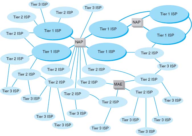
FIGURE 9.2 Basic Internet architecture. ISP = Internet service provider; MAE = metropolitan area exchange; NAP = network access point
In the early 1990s, when the Internet was still primarily run by the U.S. National Science Foundation (NSF), the NSF established four main NAPs in the United States to connect the major tier 1 ISPs. When the NSF stopped funding the Internet, the companies running these NAPs began charging the ISPs for connections, so today the NAPs in the United States are all not-for-profit organizations or commercial enterprises run by various common carriers such as AT&T and Sprint. As the Internet has grown, so too has the number of NAPs; today there are about a dozen NAPs in the United States with many more spread around the world.
Network access points were originally designed to connect only large tier 1 ISPs. These ISPs in turn provide services for their customers and also to regional ISPs (some-times called tier 2 ISPs) such as Cogent Communications Comcast, or France Telcom. These tier 2 ISPs rely on the tier 1 ISPs to transmit their messages to ISPs in other countries. Tier 2 ISPs, in turn, provide services to their customers and to local ISPs (sometimes called ISPs) who sell Internet access to individuals. As the number of ISPs grew, a new form of NAP called a metropolitan area exchange (MAE) emerged. MAEs are smaller versions of NAPs and typically link a set of regional ISPs whose networks come together in major cities (Figure 9.2).
Because most NAPs, MAEs, and ISPs now are run by commercial firms, many of the early restrictions on who could connect to whom have been lifted. Most now openly solicit business from all tiers of ISPs and even large organizations. Regional and local ISPs often will have several connections into other ISPs to provide backup connections in case one Internet connection fails. In this way, they are not dependent on just one higher-level ISP.
In general, ISPs at the same level do not charge one another for transferring messages they exchange. That is, a national tier 1 ISP does not charge another national tier 1 ISP to transmit its messages. This is called peering. Figure 9.2 shows several examples of peering. It is peering that makes the Internet work and has led to the belief that the Internet is free. This is true to some extent, but higher-level ISPs normally charge lower-level ISPs to transmit their data (e.g., a tier 1 will charge a tier 2 and a tier 2 will charge a tier 3). And of course, any ISP will charge individuals like us for access!
In October 2005, an argument between two national ISPs shut down 45 million Web sites for a week. The two ISPs had a peering agreement but one complained that the other was sending it more traffic than it should so it demanded payment and stopped accepting traffic, leaving large portions of the network isolated from the rest of the Internet. The dispute was resolved, and they began accepting traffic from each other and the rest of the Internet again.
Peering has risen to a new level in recent years with the arrival of Internet Exchange Points (IXPs). An IXP, which is often run by a not-for-profit cooperative organization, permits any ISP (or large organization) to connect to its network. Some IXPs charge connection fees, others charge membership fees, and others don't charge at all. Once connected to the IXP, the ISP negotiates peering agreements with other ISPs who are members of the IXP, and then begins exchanging Internet traffic.
In Figure 9.2, each of the ISPs are autonomous systems, as defined in Chapter 5. Each ISP is responsible for running its own interior routing protocols and for exchanging routing information via the Border Gateway Protocol (BGP) exterior routing protocol (see Chapter 5) at NAPs, MAEs, IXPs, and any other connection points between individual ISPs.
9.2.2 Connecting to an ISP
Each of the ISPs is responsible for running its own network that forms part of the Internet. ISPs make money by charging customers to connect to their part of the Internet. Local ISPs charge individuals for broadband or dial-up access whereas national and regional ISPs (and sometimes local ISPs) charge larger organizations for higher-speed access.
Each ISP has one or more points of presence (POP). A POP is simply the place at which the ISP provides services to its customers. To connect into the Internet, a customer must establish a circuit from his or her location into the ISP POP. For individuals, this is often done using a DSL modem or cable modem (Figure 9.3). This connects to the DSL multiplexer at the ISP and from there to a remote-access server (RAS), which checks to make sure the user is a valid customer. Once logged in, the user can begin sending TCP/IP packets from his or her computer to the POP. Figure 9.3 shows a POP using a switched backbone with a layer-2 switch. The POP backbone can take many forms, as we discussed in Chapter 7.

FIGURE 9.3 Inside an Internet service provider (ISP) point of presence (POP). ATM = asynchronous transfer mode; CSU = channel service unit; DSU = data service unit; MAE = metropolitan area exchange; NAP = network access point
In the next section, we will discuss Internet access technologies such as in DSL and cable modem in more detail. Customers who need more network capacity simply lease a higher-capacity circuit. Figure 9.3 shows corporate customers with T1, T3, and OC-3 connections into the ISP POP. It is important to note that the customer must pay for both Internet access (paid to the ISP) and for the circuit connecting from their location to the POP (usually paid to the local exchange carrier [e.g., BellSouth, AT&T], but sometimes the ISP also can provide circuits). For a T1 connection, for example, a company might pay the local exchange carrier $400 per month to provide the T1 circuit from its offices to the ISP POP and also pay the ISP $300 per month to provide the Internet access.
As Figure 9.3 shows, the ISP POP is connected in turn to the other POPs in the ISP's network. Any messages destined for other customers of the same ISP would flow within the ISP's own network. In most cases, the majority of messages entering the POP are sent outside of the ISP's network and thus must flow through the ISP's network to the nearest NAP/MAE/IXP. and from there, into some other ISP's network.
This can be less efficient than one might expect. For example, suppose you are connected to the Internet via a local tier 3 ISP in Minneapolis and request a Web page from another organization in Minneapolis. A short distance, right? Maybe not. If the other organization uses a different local tier 3 ISP, which in turn uses a different regional tier 2 ISP for its connection into the Internet, the message may have to travel all the way to the nearest NAP/MAE/IXP, which could be in Chicago, Dallas, or New York, before it can move between the two separate parts of the Internet.
9.1 INSIDE THE SEATTLE INTERNET EXCHANGE POINT
MANAGEMENT FOCUS
The Seattle Internet Exchange (SIX) was established in April 1997 by two small ISPs with offices in Seattle's Westin Building. The ISPs had discovered that in order to send data to each other's network in the same building, their data traveled to Texas and back. They decided to peer and installed a 10Base-T Ethernet hub connecting their two networks so that traffic flowed between them much faster.
In June 1997, a third small ISP joined and connected its network into the hub. Gradually word spread and other small ISPs began to connect. In May 1988, the first tier 1 ISP connected its network, and traffic grew enough so that the old 10 Mbps hub was replaced by a 10/100 Ethernet switch. As an aside, we'll note that the switch you have in your house or apartment today probably has more capacity than this switch. In February 1999, Microsoft connected its network, and traffic took off again. In September, 2001 the 10/100 Ethernet switch was replaced by a 10/100/1000 Ethernet switch.
Today, SIX offers 1 Gbps and 10 Gbps Ethernet connections. The first 1 Gbps connection is free; all subsequent 1 Gbps connections cost a onetime fee of $1000. 10 Gbps connections cost a onetime fee of $5000. Of course, you have to pay a common carrier to provide a network circuit into the Westin Building and then pay the Westin Building a small fee to run a fiber cable from the building's MDC to the SIX network facility. Traffic averages between 30 Gbps and 60 Gbps across the SIX network.
About 150 ISPs (e.g., AT&T, AboveNet, Shaw, Saskatchewan Telecommunications) and corporations (e.g., Google, Amazon, Yahoo) are members of SIX. About half of the members are open to peering with anyone who joins SIX. The rest, mostly tier 1 ISPs and well-known corporations, are selective or restrictive in their peering agreements, which means that they are already well-connected into the Internet and want to ensure that any new peering agreements
__________
SOURCE: www.seattleix.net
9.2.3 The Internet Today
Sprint is one of the tier 1 ISPs in North America. Figure 9.4 shows Sprint's North American backbone as it existed while we were writing this book; it will have changed by the time you read this. As you can see, Sprint has a number of Internet circuits across the United States and Canada. Many interconnect in Chicago where Sprint connects into the Chicago NAP. Sprint also connects into major NAPs and MAEs in Reston, Virginia; Miami; Los Angeles; San Jose; Palo Alto; Vancouver; Calgary; Toronto; and Montreal. Most of the circuits are SONET OC-12, but a few are OC-48 and OC-192.

FIGURE 9.4 Sprint's North American Internet backbone
Today, the backbone circuits of the major U.S. national ISPs operate at SONET OC-48 and OC-192. Most of the largest national ISPs (e.g., Sprint, AT&T) have converted their principal backbones to OC-192 (10 Gbps). A few are now experimenting with OC-768 (80 Gbps), and several are in the planning stages with OC-3072 (160 Gbps). This is good because the amount of Internet traffic has been growing rapidly. The Internet traffic in the U.S. was about 80 Tbps (80 trillion bits per second) in 2011.
As traffic increases, ISPs can add more and faster circuits relatively easily, but where these circuits come together at NAPs and MAEs, bottlenecks are becoming more common. Network vendors such as Cisco and Juniper are making larger and larger switches capable of handling these high-capacity circuits, but it is a daunting task. When circuit capacities increase by 100 percent, switch manufacturers also must increase their capacities by 100 percent. It is simpler to go from a 622 Mbps circuit to a 10 Gbps circuit than to go from a 20 Gbps switch to a 200 Gbps switch.
The Internet is constantly changing. Up-to-date maps of the major ISPs whose networks make up large portions of the Internet are available at navigators.com/isp.html.
9.3 INTERNET ACCESS TECHNOLOGIES
There are many ways in which individuals and organizations can connect to an ISP. Most individuals use DSL or cable modem. As we discussed in the preceding section, many organizations lease T1 or T3 lines into their ISPs. DSL and cable modem technologies are commonly called broadband technologies because they provide higher-speed communications than traditional modems.1
It is important to understand that Internet access technologies are used only to connect from one location to an ISP. Unlike the WAN technologies in the previous chapter, Internet access technologies cannot be used for general-purpose networking from any point to any point. In this section, we discuss four principal Internet access technologies (DSL, cable modem, fiber to the home, and WiMax). Of course, many users connect to the Internet using Wi-Fi on their laptops from public access points in coffee shops, hotels and airports. Since we discussed Wi-Fi in Chapter 6, we won't discuss it here.
9.3.1 Digital Subscriber Line (DSL)
Digital subscriber line (DSL) is a family of point-to-point technologies designed to provide high-speed data transmission over traditional telephone lines.2 The reason for the limited capacity on traditional telephone circuits lies with the telephone and the switching equipment at the end offices. The actual cable in the local loop from a home or office to the telephone company end office is capable of providing much higher data transmission rates. So DSL usually requires just changing the telephone equipment, not rewiring the local loop, which is what has made it so attractive.
Architecture DSL uses the existing local loop cable but places different equipment on the customer premises (i.e., the home or office) and in the telephone company end office. The equipment that is installed at the customer location is called the customer premises equipment (CPE). Figure 9.5 shows one common type of DSL installation. (There are other forms.) The CPE in this case includes a line splitter that is used to separate the traditional voice telephone transmission from the data transmissions. The line splitter directs the telephone signals into the normal telephone system so that if the DSL equipment fails, voice communications are unaffected.
The line splitter also directs the data transmissions into a DSL modem, which is sometimes called a DSL router. As you will recall from Chapter 3, this is both a modem and an FDM multiplexer. The DSL modem produces Ethernet 100Base-T packets so it can be connected directly into a computer or to a router and hub and can serve the needs of a small network. Most DSL companies targeting home users combine all of these devices (and a wireless access point) into one device so that consumers just have to install one box, rather than separate line splitters, modems, routers, switches and access points.
Figure 9.5 also shows the architecture within the local carrier's end office (i.e., the telephone company office closest to the customer premises). The local loops from many customers enter and are connected to the main distribution facility (MDF). The MDF works like the CPE line splitter; it splits the voice traffic from the data traffic and directs the voice traffic to the voice telephone network and the data traffic to the DSL access multiplexer (DSLAM). The DSLAM demultiplexes the data streams and converts them into ATM data, which are then distributed to the ISPs. Some ISPs are collocated, in that they have their POPs physically in the telephone company end offices. Other ISPs have their POPs located elsewhere.

FIGURE 9.5 Digital subscriber line (DSL) architecture. ATM = asynchronous transfer mode; ISP = Internet service provider; POP = point of presence
Types of DSL There are many different types of DSL. The most common type today is asymmetric DSL (ADSL). ADSL uses frequency division multiplexing (see Chapter 3) to create three separate channels over the one local loop circuit. One channel is the traditional voice telephone circuit. A second channel is a relatively high-speed simplex data channel downstream from the carrier's end office to the customer. The third channel is a slightly slower duplex data channel primarily used for upstream from the customer to the carrier's end office.3 ADSL is called asymmetric because its two data channels have different speeds. Each of the two data channels are further multiplexed using time division multiplexing so they can be further subdivided.

FIGURE 9.6 Digital subscriber line data rates
The size of the two digital channels depends on the distance from the CPE to the end office. The shorter the distance, the higher the speed, because with a shorter distance, the circuit suffers less attenuation and higher-frequency signals can be used, providing a greater bandwidth for modulation. Figure 9.6 lists the common types of DSL.
9.3.2 Cable Modem
One alternative to DSL is the cable modem, a digital service offered by cable television companies. There are several competing standards, but the Data over Cable Service Interface Specification (DOCSIS) standard is the dominant one. DOCSIS is not a formal standard but is the one used by most vendors of hybrid fiber coax (HFC) networks (i.e., cable networks that use both fiber-optic and coaxial cable). As with DSL, these technologies are changing rapidly.4
Architecture Cable modem architecture is very similar to DSL—with one very important difference. DSL is a point-to-point technology, whereas cable modems use shared multipoint circuits. With cable modems, each user must compete with other users for the available capacity. Furthermore, because the cable circuit is a multipoint circuit, all messages on the circuit go to all computers on the circuit. If your neighbors were hackers, they could use pocket sniffers such as Ethereal (see Chapter 4) to read all messages that travel over the cable, including yours.
Figure 9.7 shows the most common architecture for cable modems. The cable TV circuit enters the customer premises through a cable splitter that separates the data transmissions from the TV transmissions and sends the TV signals to the TV network and the data signals to the cable modem. The cable modem (both a modem and frequency division multiplexer) translates from the cable data into Ethernet packets, which then are directed into a computer to a router and hub for distribution in a small network. As with DSL, cable modem companies usually combine all of these separate devices into one or two devices to make it easier for the home consumer to install.

FIGURE 9.7 Cable modem architecture. ISP = Internet service provider; POP = point of presence
The cable TV cable entering the customer premises is a standard coaxial cable. A typical segment of cable is shared by anywhere from 300 to 1,000 customers, depending on the cable company that installed the cable. These 300 to 1,000 customers share the available data capacity, but of course, not all customers who have cable TV will choose to install cable modems. This coax cable runs to a fiber node, which has an optical-electrical (OE) converter to convert between the coaxial cable on the customer side and fiber-optic cable on the cable TV company side. Each fiber node serves as many as half a dozen separate coaxial cable runs.
The fiber nodes are in turn connected to the cable company distribution hub (sometimes called a headend) through two separate circuits: an upstream circuit and a downstream circuit. The upstream circuit, containing data traffic from the customer, is connected into a cable modem termination system (CMTS). The CMTS contains a series of cable modems/multiplexers and converts the data from cable modem protocols into protocols needed for Internet traffic, before passing them to a router connected to an ISP POP. Often, the cable company is an Internet regional ISP, but sometimes it just provides Internet access to a third-party ISP.
The downstream circuit to the customer contains both ordinary video transmissions from the cable TV video network and data transmissions from the Internet. Downstream data traffic enters the distribution hub from the ISP POP and is routed through the CMTS, which produces the cable modem signals. This traffic is then sent to a combiner, which combines the Internet data traffic with the ordinary TV video traffic and sends it back to the fiber node for distribution.
MANAGEMENT FOCUS
The speed of your Internet connection depends upon many things, such as your computer's settings, the connection from your computer to your ISP, and the connections your ISP has into the Internet. There are many Internet sites that enable you to test how fast your Internet connection actually is. Our favorite is speedtest.net.
Types of Cable Modems The DOCSIS standard provides many types of cable modems. The maximum speed is about 150 Mbps downstream and about 100 Mbps upstream, although most cable TV companies provide at most 50 Mbps downstream and 10 Mbps upstream. Cable modems can be configured to limit capacity, so the most common speeds offered by most cable providers range from 1–10 Mbps downstream and 256 Kbps to 1 Mbps upstream. Of course, this capacity is shared, so an individual user will only see this when no other computers on his or her segment are active.
9.3.3 Fiber to the Home
Fiber to the home (FTTH) is exactly what it sounds like: running fiber-optic cable into the home. The traditional set of hundreds of copper telephone lines that run from the telephone company switch office is replaced by one fiber-optic cable that is run past each house or office in the neighborhood. Data are transmitted down the signal fiber cable using wavelength division multiplexing (WDM), providing hundreds or thousands of separate channels. As of 2011, FTTH was installed in about 7 million homes in the United States and another 10 million homes had access to FTTH. The largest implementations were in test market cities in North Dakota, Virginia, and Pennsylvania.
Architecture FTTH architecture is very similar to DSL and cable modem. At each subscriber location, an optical unit network (ONU) (also called an optical network terminal [ONT]) acts like a DSL modem or cable modem and converts the signals in the optical network into an Ethernet format. The ONU acts as an Ethernet switch and can also include a router. FTTH is a dedicated point-to-point service like DSL, not a shared multipoint service like cable modem.
Providers of fiber to the home can use either active optical networking or passive optical networking to connect the ONU in the customer's home. Active networking means that the optical devices require electrical power and works in much the same way as traditional electronic switches and routers. Passive optical networking devices require no electrical current and thus are quicker and easier to install and maintain than traditional electrical-based device, but because they are passive, the optical signal fades quickly, giving a maximum range of about 10 miles.
Types of FTTH There are many types of FTTH and because FTTH is a new technology, these types are likely to evolve as FTTH enter the market and becomes more widely adopted. Common types provide 10–100 Mbps downstream and 1–10 Mbps upstream. The most commonly used type provides 15 Mbps downstream and 4 Mbps upstream. Newer versions have been announced targeted at business users that provide 1 Gbps down and 100 Mbps up.
9.3.4 WiMax
WiMAX (short for Worldwide Interoperability for Microwave Access) is the commercial name for a set of standards developed by the IEEE 802.16 standards group. WiMax is family of technologies that is much like the 802.11 Wi-Fi family. It reuses many of the Wi-Fi components and was designed to connect easily into Ethernet LANs. WiMax can be used as a fixed wireless technology to connect a house or an office into the Internet, but its future lies in its ability to connect mobile laptops and smart phones into the Internet. Some vendors have started calling WiMax 4G, planning to use it as a replacement for today's 3G mobile phone networks.
WiMax is a relatively old technology. The problem is that computer manufacturers have been waiting for ISPs to build WiMax networks before they build WiMax into their computers. Meanwhile, ISPs have been waiting for computer manufacturers to provide WiMax capable computers before they build WiMax networks. And so we have a Catch-22.
This changed in 2011 when Intel developed a cheap WiMax chip set. Many computer manufacturers are including WiMax on their laptops so ISPs have started building WiMax networks. Many large cities now have WiMax networks and this will gradually spread to other parts of the country.
Most experts envision a future where both Wi-Fi and WiMax coexist. Laptops and Smart phones will connect to Wi-Fi networks in home and office locations where Wi-Fi is available. If Wi-Fi is not available and the user has subscribed to WiMax services, then the laptop or smart phone will connect to the WiMax network.
Architecture Although WiMax can be used in fixed locations to provide Internet access to homes and offices, we will focus on mobile use as this is likely to be the most common use. Mobile WiMax works in much the same way as Wi-Fi. The laptop or smart phone has a WIMAX network interface card (NIC) and uses it to establish a connection to a WiMax access point (AP). Many devices use the same AP so WiMax is a shared multipoint service in which all computers must take turns transmitting. Media access control is controlled access, using a version of the 802.11 point coordination function (PCF).
WiMax uses the 2.3 GHz, 2.5 GHz, and 3.5 GHz frequency ranges in North America, although additional frequency ranges may be added. The maximum range is from 3 to 10 miles, depending on interference and obstacles between the device and the AP. Most WiMax providers in the United States are using effective ranges of 0.5 to 1.5 miles when they install WiMax APs.
Types of WiMax There are several types of WiMax available, with new versions under development. The most common type of mobile wireless provides speeds of 40 Mbps, shared among all users of the same AP. Some providers have versions that run at 70 Mbps. New versions under development promise speeds of 300 Mbps.
9.4 THE FUTURE OF THE INTERNET
9.4.1 Internet Governance
Because the Internet is a network of networks, no one organization operates the Internet. The closest thing the Internet has to an owner is the Internet Society (ISOC) (www.isoc.org). ISOC is an open-membership professional society with more than 175 organizational and 8,000 individual members in over 100 countries, including corporations, government agencies, and foundations that have created the Internet and its technologies. Because membership in ISOC is open, anyone, including students, is welcome to join and vote on key issues facing the Internet.
The ISOC mission is to ensure “the open development, evolution and use of the Internet for the benefit of all people throughout the world.”5 It works in three general areas: public policy, education, and standards. In terms of public policy, ISOC participates in the national and international debates on important issues such as censorship, copyright, privacy, and universal access. ISOC delivers training and education programs targeted at improving the Internet infrastructure in developing nations. The most important ISOC activity lies in the development and maintenance of Internet standards. ISOC works through four interrelated standards bodies: Internet Engineering Task Force (IETF), Internet Engineering Steering Group (IESG), Internet Architecture Board (IAB), and Internet Research Task Force (IRTF).
The Internet Engineering Task Force (IETF) (www.ietf.org) is a large, open international community of network designers, operators, vendors, and researchers concerned with the evolution of the Internet architecture and the smooth operation of the Internet. The IETF works through a series of working groups, which are organized by topic (e.g., routing, transport, security). The requests for comment (RFCs) that form the basis for Internet standards are developed by the IETF and its working groups.
Closely related to the IETF is the Internet Engineering Steering Group (IESG). The IESG is responsible for technical management of IETF activities and the Internet standards process. It administers the process according to the rules and procedures that have been ratified by the ISOC trustees. The IESG is directly responsible for the actions associated with entry into and movement along the Internet “standards track,” including final approval of specifications as Internet standards. Each IETF working group is chaired by a member of the IESG.
Whereas the IETF develops standards and the IESG provides the operational leadership for the IETF working groups, the Internet Architecture Board (IAB) provides strategic architectural oversight. The IAB attempts to develop conclusions on strategic issues (e.g., top-level domain names, use of international character sets) that can be passed on as guidance to the IESG or turned into published statements or simply passed directly to the relevant IETF working group. In general, the IAB does not produce polished technical proposals but rather tries to stimulate action by the IESG or the IETF that will lead to proposals that meet general consensus. The IAB appoints the IETF chairperson and all IESG members, from a list provided by the IETF nominating committee. The IAB also adjudicates appeals when someone complains that the IESG has failed.
9.1 REGISTERING AN INTERNET DOMAIN NAME
TECHNICAL FOCUS
Until the 1990s, there was only a moderate number of computers on the Internet. One organization was responsible for registering domain names (sets of application layer addresses) and assigning IP addresses for each top-level domain (e.g., .COM). Network Solutions, for example, was the sole organization responsible for domain name registrations for the .COM, .NET, and .ORG domains. In October 1998, the Internet Corporation for Assigned Names and Numbers (ICANN) was formed to assume responsibility for the IP address space and domain name system management.
In spring 1999, ICANN established the Shared Registration System (SRS) that enabled many organizations to perform domain name registration and address assignment using a shared database. More than 80 organizations are now accredited by ICANN as registrars and are permitted to use the SRS. Each registrar has the right to assign names and addresses in one or more top-level domains. For a list of registrars and the domains they serve, see www.internic.com.
If you want to register a new domain name and obtain an IP address, you can contact any accredited registrar for that top-level domain. One of the oldest privately operated registrars is register.com. Each registrar follows the same basic process for registering a name and assigning an address, but each may charge a different amount for their services. In order to register a name, you must first check to see if it is available (i.e., that no one else has registered it). If the name has already been registered, you can find out who owns it and perhaps attempt to buy it from them.
If the domain name is available, you will need to provide the IP address of the DNS server that will be used to store all IP addresses in the domain. Most large organizations have their own DNS servers, but small companies and individuals often use the DNS of their ISP.
The Internet Research Task Force (IRTF) operates much like the IETF through small research groups focused on specific issues. Whereas IETF working groups focus on current issues, IRTF research groups work on long-term issues related to Internet protocols, applications, architecture, and technology. The IRTF chairperson is appointed by the IAB.
9.4.2 Building the Future
The Internet is changing. New applications and access technologies are being developed at lightning pace. But these innovations do not change the fundamental structure of the Internet. It has evolved more slowly because the core technologies (TCP/IP) are harder to change gradually; it is difficult to change one part of the Internet without changing the attached parts.
Many organizations in many different countries are working on dozens of different projects in an attempt to design new technologies for the next version of the Internet.6
The two primary American projects working on the future Internet got started at about the same time in 1996. The U.S. National Science Foundation provided $100 million to start the Next Generation Internet (NGI) program, and 34 universities got together to start what turned into the University Corporation for Advanced Internet Development (UCAID), which developed the Abilene network, commonly called Internet2. In 1997, the Canadian government established the Advanced Research and Development Network Operations Center (ARDNOC), which developed CA*net, the Canadian project on the future Internet.7
Figure 9.8 shows the major high-speed circuits in the Internet2 network and the CA*net network. All the major circuits in these networks are OC-192 (10 Gbps). The two networks peer in Seattle, Chicago, and New York. National Lambda Rail (www.nlr.net) is another major high-speed network that is experimenting with long distance Ethernet (10 GbE) running over fiber-optic circuits.
Each of the networks has a set of access points called gigapops, so named because they provide a point of presence at gigabit speeds. Although traditional Internet NAPs provide connections between networks at T3, OC-1, OC-3, and OC-12 speeds, gigapops are designed to provide access at much higher speeds so that different networks can exchange data at much higher rates of speed, usually OC-198 or 10 Gbps. Gigapops also usually provide a wider range of services than traditional NAPs that are primarily just data exchange points.
Besides providing very high-speed Internet connections, these networks are intended to experiment with new protocols that one day may end up on the future Internet. For example, most of these networks run IPv6 as the primary network layer protocol, rather than IPv4. Most are also working on new ways to provide quality of service (QoS) and multicasting. Some, such as Internet2, are also working on developing new applications for a high-speed Internet, such as tele-immersion and videoconferencing.
9.3 INSIDE THE PACIFIC/NORTHWEST GIGAPOP
MANAGEMENT FOCUS
The Pacific/Northwest Gigapop is located in Seattle, Washington, and is run by the University of Washington and University Corporation for Advanced Internet Development (i.e., Internet2). It provides gigabit Ethernet and SONET OC-192 (10 Gbps) connections to several high-speed networks such as Abilene, CA*net, Microsoft, and the Defense Research and Engineering Network, which is funded by the U.S. Department of Defense. It also provides a network access point for these high-speed networks to connect to lower-speed networks of the traditional Internet, such as those run by Sprint, AT&T, Singapore's SingAREN, and Australia's AARNet, as well as a number of universities in the Pacific Northwest.
The basic core of the gigapop is a set of high-speed switches, connected to high-speed routers. High-speed networks, such as Abilene, connect directly into the core devices whereas lower-speed networks connect into the core via a setofrouters.
__________
SOURCE: www.pnw-gigapop.net.

FIGURE 9.8 Selected high-speed Internet 2 backbones
9.5 IMPLICATIONS FOR MANAGEMENT
Several years ago, there was great concern that the traffic on the Internet would exceed its capacity. The growth of traffic on the Internet was increasing significantly faster than the construction of new Internet circuits; several experts predicted the collapse of the Internet. It did not happen for the simple reason that companies could make money by building new circuits and charging for their use. Today, there are a large number of fiber-optic circuits that have been built but not yet been turned on. Wavelength division multiplexing technologies mean that 10 to 20 times more data can now be transmitted through the same fiber-optic cable (see Chapter 3). Many countries, companies, and universities are now building the Next Generation Internet using even newer, experimental, very high-speed technologies. The Internet will not soon run out of capacity.
In recent years, there has been a blossoming of new “broadband” technologies for higher speed Internet access. Individuals and organizations can now access the Internet at relatively high speeds—much higher speeds than we would have even considered reasonable 5 to 10 years ago. This means that it is now simple to move large amounts of data into most homes and businesses in North America. As a result, software applications that use the Internet can provide a much richer multimedia experience than ever before.
In previous chapters, we have described how there has been a significant reduction in a number of different technologies in use in LANs, backbones, and WANs over the past few years. We are about to enter that stage with regard to Internet access technologies. Today there are many choices; over the next two years a few dominant standards will emerge, and the market will solidify around those standards. Organizations that invest in the technologies that ultimately become less popular will need to invest significant funds to replace those technologies with the dominant standards. The challenge, of course, is to figure out which technology standards will become dominant. Will it be cable modem and DSL, or fiber to the home? Only time will tell.
SUMMARY
How the Internet Works The Internet is a set of separate networks, ranging from large national ISPs to midsize regional ISPs to small local ISPs, that connect with one another at NAPs and MAEs. NAPs and MAEs charge the ISPs to connect, but similar-sized ISPs usually do not charge each other to exchange data. Each ISP has a set of points of presence through which it charges its users (individuals, businesses, and smaller ISPs) to connect to the Internet. Users connect to a POP to get access to the Internet. This connection may be via a dial-up modem over a telephone line or via a higher-speed circuit such as DSL, cable modem, or a T1.
DSL DSL enables users to connect to an ISP POP over a standard point-to-point telephone line. The customer installs a DSL modem that connects via Ethernet to his or her computer system. The modem communicates with a DSLAM at the telephone company office, which sends the data to the ISP POP. ADSL is the most common type of DSL and often provides 1.5 Mbps downstream and 384 Kbps upstream. VDSL is a faster version that runs over short distances and has speeds up to 51.8 Mbps.
Cable Modem Cable modems use a shared multipoint circuit that runs through the cable TV cable. They also provide the customer with a modem that connects via Ethernet to his or her computer system. The modem communicates with a CMTS at the cable company office, which sends the data to the ISP POP. The DOCSIS standard is the dominant standard, but there are no standard data rates today. Typical downstream speeds range between 1 Mbps and 10 Mbps, and typical upstream speeds range between 256 Kbps and 1 Mbps.
Fiber to the Home FTTH is a new technology that is not widely implemented. It uses fiber optic cables to provide high speed data services (e.g., 100 Mbps) to homes and offices.
WiMax WiMax is sometimes called the new 4G mobile Internet. It works similarly to Wi-Fi, in that it enables mobile users to connect into the Internet at speeds of 40 to 70 Mbps.
The Future of the Internet The closest the Internet has to an owner is the ISOC, which works on public policy, education, and Internet standards. Standards are developed through four related organizations governed by ISOC. The IETF develops the actual standards through a series of working groups. The IESG manages IETF activities. The IAB sets long-term strategic directions, and the IRTF works on future issues through working groups in much the same way as the IETF. There are many different organizations currently working on the next generation of the Internet, including the Abilene network, vBNS, and CA*net. Although each is working in a slightly different fashion, all join together with one another and parts of the regular Internet at gigapops (gigabit points of presence).
KEY TERMS
Abilene network
Advanced Research and Development Network Operations Center (ARDNOC)
asymmetric DSL (ADSL)
autonomous systems
broadband technologies
cable modem
cable modem termination system (CMTS)
CA*net
customer premises equipment (CPE)
Data over Cable Service Interface Specification (DOCSIS)
digital subscriber line (DSL)
distribution hub
DSL access multiplexer (DSLAM)
DSL modem
fiber-to-the-home (FTTH)
gigapop
Internet Architecture Board (IAB)
Internet Corporation for Assigned Names and Numbers (ICANN)
Internet Engineering Steering Group (IESG)
Internet Engineering Task Force (IETF)
Internet Research Task Force (IRTF)
Internet Service Provider (ISP)
Internet Society (ISOC)
Internet2
line splitter
local ISP
local loop
main distribution facility (MDF)
metropolitan area exchange (MAE)
mobile wireless
national ISP
network access point (NAP)
Next Generation Internet (NGI)
optical-electrical (OE) converter
optical network unit (ONU)
peering
point of presence (POP)
regional ISP
remote-access server (RAS)
request for comment (RFC)
tier 1 ISP
tier 2 ISP
tier 3 ISP
University Corporation for Advanced Internet Development (UCAID)
WiMax
QUESTIONS
- What is the basic structure of the Internet?
- Explain how the Internet is a network of networks.
- Compare and contrast an NAP and a MAE.
- What is a POP?
- Explain one reason why you might experience long response times in getting a Web page from a server in your own city.
- What type of circuits are commonly used to build the Internet today? What type of circuits are commonly used to build Internet2?
- Compare and contrast cable modem and DSL.
- Explain how DSL works.
- How does a DSL modem differ from a DSLAM?
- Explain how ADSL works.
- Explain how a cable modem works.
- What is an OE converter? A CMTS?
- Which is better, cable modem or DSL? Explain.
- Explain how FTTH works.
- What are some future technologies that might change how we access the Internet?
- Explain how WiMax works.
- What are the principal organizations responsible for Internet governance, and what do they do?
- How is the IETF related to the IRTF?
- What are two principal American organizations working on the future of the Internet?
- What is Internet2?
- What is a gigapop?
- There are many different organizations working on their vision of a high-speed Internet. Is this good or bad? Would we be better off just having one organization working on this and coordinating the work?
- Today, there is no clear winner in the competition for broadband Internet access. What technology or technologies do you think will dominate in two years’ time? Why?
- Would you be interested in subscribing to 100 Mbps FTTH for a monthly price of $75? Why or why not?
- Many experts predicted that small, local ISPs would disappear as regional and national ISPs began offering local access. This hasn't happened. Why?
EXERCISES
9-1. Describe the current network structure of the Abilene network, the vBNS network, and the CA*net network.
9-2. Provide the service details (e.g., pricing and data rates) for at least two high-speed Internet access service providers in your area.
9-3. Some people are wiring their homes for 100Base-T. Suppose a friend who is building a house asks you what—if any—network to put inside the house and what Internet access technology to use. What would you recommend?
9-4. Provide service details (e.g., pricing and data rates) for WiMax in your area or a large city such as New York or Los Angeles.
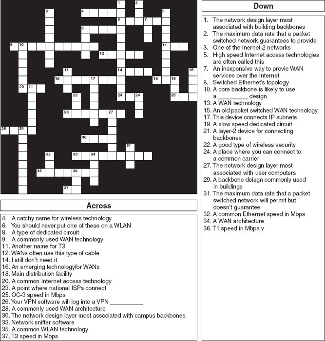
9-5. Do the puzzle below.
I. Cathy's Collectibles
Your cousin Cathy runs a part-time business out of her apartment. She buys and sells collectibles such as antique prints, baseball cards, and cartoon cells and has recently discovered the Web with its many auction sites. She has begun buying and selling on the Web by bidding on collectibles at lesser-known sites and selling them at a profit at more well-known sites. She downloads and uploads lots of graphics (pictures of the items she's buying and selling). She is getting frustrated with the slow Internet access she has with her 56-Kbps dial-up modem and asks you for advice. DSL is available at a cost of $30 per month for 1.5 Mbps down and 384 Kbps up. Cable modem service is available for a cost of $30 per month for 3 Mbps down and 640 Kbps up. Explain the differences in these services and make a recommendation.
II. Surfing Sam
Sam likes to surf the Web for fun, to buy things, and to research for his classes. Suppose the same Internet access technologies are available as in mini-case I above. Explain the differences in these services and make a recommendation.
III. Cookies Are Us
Cookies Are Us runs a series of 100 cookie stores across the midwestern United States and central Canada. At the end of each day, the stores express-mail a diskette or two of sales and inventory data to headquarters, which uses the data to ship new inventory and plan marketing campaigns. They have decided to move data over a WAN or the Internet. What type of a WAN topology and service (see Chapter 8) or Internet connection would you recommend? Why?
IV. Organic Foods
Organic Foods operates organic food stores in Toronto. The store operates like a traditional grocery store but offers only organically grown produce and meat, plus a wide array of health food products. Organic Foods sells memberships, and its 3,000 members receive a discount on all products they buy. There are also special member events and sales promotions each month. Organic Foods wants to open a new Internet site that will enable it to email its members monthly and provide up-to-date information and announcements about new products, sales promotions, and member events on its Web site. It has two options. First, it could develop the software on its own server in its office and connect the office (and the server) to the internet via DSL, T1, or similar connection from its offices to an ISP. Alternately, it could pay the ISP to host the Web site on its servers and just connect the office to the ISP for internet service. Costs for several Internet access options are shown in mini-case I above. In addition, T1 service would cost $1,000 to install and $900 per month to operate; frame relay would cost $1,000 to install and $300 per month for 256kps or $500 for 1.5 mbps. Web hosting would cost $100–400 per month, depending on the traffic. Which would you recommend and what size of an internet connection would you recommend? Justify your choice.
HANDS-ON ACTIVITY 9A
Seeing the Internet
The Internet is a network of networks. One way to see this is by using the VisualRoute software. VisualRoute is a commercial package, but provides a demonstration on its Web site. Go to visualroute.visualware.com and register to use their free service. Then enter a URL and watch as the route from your computer to the destination is traced and graphed. Figure 9.9 shows the route from my house in Indiana to the City University of Hong Kong.


FIGURE 9.10 Internet traffic reports
Another interesting site is the Internet Traffic Report (www.internettrafficreport.com). This site shows how busy the parts of the Internet are in real time. The main page enables you to see the current status of the major parts of the world, including a “traffic index” that rates performance on a 100-point scale. You can also see the average response time at key Internet NAPs, MAEs, and peering points (at least those that have agreed to be monitored), which is an average of 135 milliseconds. It also shows the global packet loss rates—the percent of packets discarded due to transmission errors—(an average of 3 percent today).
By clicking on a region of the world you can see the same statistics for routers in that region. If you click on a specific router you can see a graph of its performance over the past 24 hours. Figure 9.10 shows the statistics for one router operated by Sprint.
You can also get traffic reports for Internet 2 at atlas.grnoc.iu.edu/I2.html. Figure 9.11 shows the “weathermap” on the Internet 2 Abilene network. Each circuit is color coded (although it's hard to see in this two-color figure). The weathermap shows traffic in both directions because the circuits are full duplex. The circuit from Atlanta to Chicago, for example, is running at 5 percent of capacity, while the circuit from Chicago to Atlanta is running at 10 percent of capacity. You can also click on any circuit to see a graph of traffic over the last 24 hours.
Deliverables
- Trace the route from your computer to CNN.com and to Oxford University www.ox.ac.uk.
- Use the Internet traffic report to find the average response time and packet loss in Asia, Australia, and North America. Pick a router in North America and report its typical response time for the past 24 hours.

- How busy are the Internet2 links from Chicago to Atlanta in bps right now? What was the peak traffic on these circuits over the last 24 hours?
HANDS-ON ACTIVITY 9B
Measuring Your Speed
The download and upload speeds you get on the Internet depend partly on the type of Internet access you have. The speeds also depend on how your ISP is connected to other ISPs, how busy the Internet is today, and how busy the Web site you're working with is. The last two factors (Internet traffic, and Web traffic at the server) are beyond your control. However, you can chose what type of Internet connection you have and who your ISP is.
There are many sites on the Internet that can test the speed of your Internet connection. Our favorite speed site is speedtest.net. Speedtest.net has lots of advertising; ignore it (and any “windows scan” offer) and just do the speed test. You begin by selecting a server for the test. I selected a server in Nova Scotia and tested how fast the connection was between it and my computer in Indiana, which is connected to the Internet using Comcast's cable modem service. Figure 9.12 shows that my download speed was about 2.5 Mbps and my upload speed was about 2.4 Mbps. I ran the same test to a server closer to my computer in Indiana and got and average download speed of 4.2 Mbps and upload speed of 3.6 Mbps. The speeds to a server in Mexico were about 1.4 Mbps up and 1.0 down.
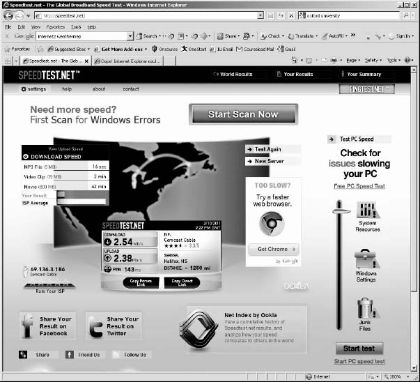
FIGURE 9.12 A speed test on my computer in Indiana
Deliverable
- Test the upload and download speeds to a server close to your computer and to one far away from you.
1 Broadband is a technical term that means “analog transmission” (see Chapter 3). The new broadband technologies often use analog transmission, so they were called broadband. However, the term broadband has been corrupted in common usage so that to most people it usually means “high speed.”
2 DSL is rapidly changing because it is so new. More information can be found from the DSL forum (www.adsl.com, www.dsllife.com) and the ITU-T under standard G.992.
3 Because the second data channel is intended primarily for upstream data communication, many authors imply that this is a simplex channel, but it is actually a set of half-duplex channels.
4 More information can be found at www.cablemodem.com and www.cable-modems.org.
5 See www.isoc.org/isoc/mission.
6 For a listing of several major international projects, see www.startap.net.
7 For more information on these projects, see www.internet2.org and www.canarie.ca.