


RDMA over Converged Ethernet (RoCE) improvements
This appendix briefly describes the optional RDMA over Converged Ethernet (RoCE) feature improvements of the IBM z13 server. It includes the following topics:
E.1 Overview
z13 delivers improvements in the RoCE exploitation. Now the adapter can be shared up to 31 partitions and the two ports are enabled to be used in z/OS. z13 improves the usability of the RoCE feature by using existing z Systems and industry standard communications technology along with emerging new network technology:
•Remote Direct Memory Access (RDMA) technology provides low latency, high bandwidth, high throughput, and low processor utilization attachment between hosts.
•Shared Memory Communications over RDMA, or SMC-R, is a protocol that allows existing TCP applications to benefit transparently from RDMA for transferring data:
– SMC-R uses RoCE as the physical transport layer.
– Initial deployment is limited to z/OS to z/OS communications with a goal to expand exploitation to more operating systems and possibly appliances and accelerators.
•Single Root I/O Virtualization (SR-IOV) technology provides the capability to share the RoCe adapter between logical partitions (LPARs).
E.1.1 RDMA technology overview
RoCE is part of the InfiniBand Architecture Specification that provides InfiniBand transport over Ethernet fabrics. It encapsulates InfiniBand transport headers into Ethernet frames by using an IEEE-assigned Ethertype. One of the key InfiniBand transport mechanisms is RDMA, which is designed to allow transfer of data to or from memory on a remote system with low latency, high throughput, and low CPU utilization.
Traditional Ethernet transports, such as TCP/IP, typically use software-based mechanisms for error detection and recovery, and are based on the underlying Ethernet fabric using a “best-effort” policy. With the traditional policy, the switches typically discard packets in congestion and rely on the upper-level transport for packet retransmission. RoCE, however, uses hardware-based error detection and recovery mechanisms that are defined by the InfiniBand specification. A RoCE transport performs best when the underlying Ethernet fabric provides a lossless capability, where packets are not routinely dropped. This can be accomplished by using Ethernet flow control where Global Pause frames are enabled for both transmission and reception on each of the Ethernet switches in the path between the 10GbE RoCE Express features. This capability is enabled, by default, in the 10GbE RoCE Express feature.
There are two key requirements for RDMA as shown in Figure E-1:
•A reliable “lossless” network fabric (LAN for layer 2 data center network distance)
•An RDMA-capable network interface card (NIC) and Ethernet fabric

Figure E-1 RDMA technology overview
RDMA technology is now available on Ethernet. RoCE uses an existing Ethernet fabric (switches with Global Pause enabled) and requires advanced Ethernet hardware (RDMA-capable NICs on the host).
E.1.2 Shared Memory Communications over RDMA (SMC-R)
SMC-R is a protocol that allows TCP socket applications to transparently use RDMA.
SMC-R is a “hybrid” solution as shown in Figure E-2:
•It uses a TCP connection to establish the SMC-R connection.
•A TCP option controls switching from TCP to “out of band” SMC-R.
•The SMC-R information is exchanged within the TCP data stream.
•Socket application data is exchanged through RDMA (write operations).
•The TCP connection remains to control the SMC-R connection.
•This model preserves many critical existing operational and network management features of TCP/IP.

Figure E-2 Dynamic transition from TCP to SMC-R
The hybrid model of SMC-R uses these key existing attributes:
•It follows the standard TCP/IP connection setup.
•The hybrid model switches to RDMA (SMC-R) dynamically.
•The TCP connection remains active (idle) and is used to control the SMC-R connection.
•The hybrid model preserves the following critical operational and network management TCP/IP features:
– Minimal (or zero) IP topology changes
– Compatibility with TCP connection-level load balancers
– Preservation of the existing IP security model, such as IP filters, policies, virtual LANs (VLANs), and Secure Sockets Layer (SSL)
– Minimal network administration and management changes
•Host application software is not required to change, so all host application workloads can benefit immediately.
E.1.3 Single Root I/O Virtualization (SR-IOV)
SR-IOV is a technology that is designed to provide the capability for use by multiple LPARs by sharing the adapter between them, up to 31. SR-IOV is also designed to provide isolation of virtual functions within the PCIe RoCe adapter. For example, one LPAR cannot cause error visible to other virtual function or other LPARs. Each operating system LPAR has its own application queue in its own memory space.
Figure E-3 show concepts on Shared RoCE Mode.

Figure E-3 Share RoCE mode concepts
The Physical Function (PF) Driver Communicates to the Physical Function in the PCIe adapter. The PF Driver has a relatively limited function:
•Manages resource allocation
•Perform hardware error handling
•Perform code updates
•Run diagnostics
The Device-specific z Systems LIC connects PF Driver to Support Elements (SEs) and limited system level firmware required services.
E.2 Hardware
The 10 Gigabit Ethernet (10GbE) RoCE Express feature (FC 0411) is an RDMA-capable NIC. The integrated firmware processor (IFP) has two Resource Groups (RGs) that have firmware for the 10GbE RoCE Express feature.
E.2.1 10GbE RoCE Express feature
The 10GbE RoCE Express feature is designed to help reduce the consumption of CPU resources for applications that use the TCP/IP stack, such as WebSphere accessing a DB2 database. Using the 10GbE RoCE Express feature also helps to reduce network latency with memory-to-memory transfers that use SMC-R in z/OS V2.1. It is transparent to applications and can be used for LPAR-to-LPAR communication on a single z/OS system or server-to-server communication in a multiple CPC environment.
Table E-1 shows the differences in the number of ports and shared support for different systems.
Table E-1 RoCE number of enabled ports and shared/dedicated environment
|
System Name
|
z/OS Supported Ports
|
Shared mode
|
Dedicated mode
|
|
z13
|
2
|
YES
|
YES
|
|
zEC12
|
1
|
NO
|
YES
|
|
zBC12
|
1
|
NO
|
YES
|
The 10GbE RoCE Express feature shown in Figure E-4 on page 516 is used exclusively in the Peripheral Component Interconnect Express (PCIe) I/O drawer. Each feature has one PCIe adapter and two ports. A maximum of 16 features can be installed. The 10GbE RoCE Express feature uses a short reach (SR) laser as the optical transceiver and supports the use of a multimode fiber optic cable terminated with an LC Duplex connector. Both point-to-point connection and switched connection with an enterprise-class 10 GbE switch are supported.
If the IBM 10GbE RoCE Express features are connected to 10 GbE switches, the switches must support the following requirements:
•Global Pause function enabled
•Priority Flow Control (PFC) disabled
•No firewalls, no routing, and no intraensemble data network (IEDN)
The maximum supported unrepeated distance, point-to-point is 300 meters (984.25 ft).
A client-supplied cable is required. Three types of cables can be used for connecting the port to the selected 10 GbE switch or to the 10GbE RoCE Express feature on the attached server:
•OM3 50 micron multimode fiber optic cable rated at 2000 MHz-km terminated with an LC Duplex connector (supports 300 m (984.25 ft))
•OM2 50 micron multimode fiber optic cable rated at 500 MHz-km terminated with an LC Duplex connector (support 82 m (269 ft))
•OM1 62.5 micron multimode fiber optic cable rated at 200 MHz-km terminated with an LC Duplex connector (support 33 m (108.2 ft))

Figure E-4 10GbE RoCE Express
E.2.2 10GbE RoCE Express configuration sample
Figure E-5 illustrates a sample configuration that allows redundant SMC-R connectivity among LPAR A, B, and C, and LPAR 1, 2 and 3. Each feature can be shared or dedicated to an LPAR. Like the sample configuration, two features per LPAR are advised for redundancy.

Figure E-5 10GbE RoCE Express sample configuration
The configuration shown in Figure E-5 on page 516 allows redundant SMC-R connectivity among LPAR A, LPAR C, LPAR 1, LPAR 2, and LPAR 3. LPAR to LPAR OSD connections are required to establish the SMC-R communications. 1 GbE OSD connections can be used instead of 10 GbE. OSD connections can flow through the same 10 GbE switches or different switches.
|
z13 exclusive: Simultaneous use of both 10 GbE ports on 10GbE RoCE Express features and shared among other LPARS up to 31.
|
An OSA-Express feature, defined as channel-path identifier (CHPID) type OSD, is required to establish SMC-R. Figure E-6 shows the interaction of OSD and the RDMA over Converged Ethernet Network Interface Card (RNIC). The OSA feature might be a single or pair of 10 GbE, 1 GbE, or 1000Base-T OSAs. The OSA needs to be connected to another OSA on the system with which the RoCE feature is communicating. In Figure E-5 on page 516, 1 GbE OSD connections can still be used instead of 10 GbE and OSD connections can flow through the same 10 GbE switches.
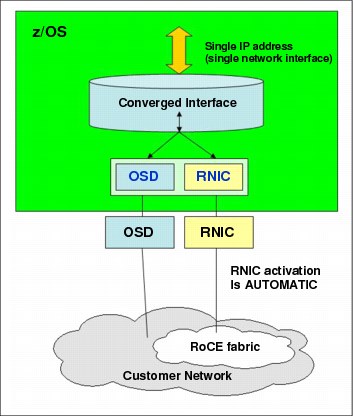
Figure E-6 RNIC and OSD interaction
The following notes refer to Figure E-6:
•The z/OS system administrator only must configure and manage the OSD interface.
•The Communication Server transparently splits and converges network traffic to and from the converged interface.
•Only OSD connectivity must be configured.
With SMC-R, the RNIC interface is dynamically and transparently added and configured.
E.2.3 Hardware configuration definitions (HCDs)
The following HCDs are important.
Function ID
The RoCE feature is identified by a hexadecimal Function Identifier (FID) in the range
00 - FF in the HCD or Hardware Management Console (HMC) to create the /input/output configuration program (IOCP) input. An FID can only be configured to one LPAR, but it is reconfigurable. The RoCE feature in a specific PCIe I/O drawer and slot to be used for the defined function can be identified by assigning a physical channel identifier (PCHID). Only one FID is supported by each PCHID.
00 - FF in the HCD or Hardware Management Console (HMC) to create the /input/output configuration program (IOCP) input. An FID can only be configured to one LPAR, but it is reconfigurable. The RoCE feature in a specific PCIe I/O drawer and slot to be used for the defined function can be identified by assigning a physical channel identifier (PCHID). Only one FID is supported by each PCHID.
Virtual Function ID
Virtual Function ID is defined when PCIe hardware is shared between LPARs. Virtual Function ID has a decimal Virtual Function Identifier (VF=) in the range 1 – n, where n is the maximum number of partitions the PCIe feature supports. For example, the RoCE feature supports up to 31 partitions, and a zEDC Express feature supports up to 15.
Physical network (PNet) ID
As one parameter for the FUNCTION statement, the PNet ID is a client-defined value for logically grouping OSD interfaces and RNIC adapters based on physical connectivity. The PNet ID values are defined for both OSA and RNIC interfaces in the HCD. z/OS Communications Server gets the information during the activation of the interfaces and associates the OSD interfaces with the RNIC interfaces that have matching PNet ID values. If you do not configure a PNet ID for the RNIC adapter, activation fails. If you do not configure a PNet ID for the OSA adapter, activation succeeds, but the interface is not eligible to use SMC-R. Figure E-7 shows the three physically separate networks defined by client.

Figure E-7 Physical network ID example
Sample IOCP FUNCTION statement
Example E-1 shows one sample IOCP FUNCTION configuration to define an RoCE Express adapter shared between LPARs.
Example E-1 IOCP FUNCTION statements
FUNCTION FID=05,PCHID=100,PART=((LP08),(LP09)),VF=1,TYPE=ROCE,PNETID=(NET1,,,)
FUNCTION FID=06,PCHID=12C,PART=((LP08),(LP09)),VF=1TYPE=ROCE,NETID=(,NET2,,)
FUNCTION FID=07,PCHID=100,PART=((LP12),(LP06)),VF=2,TYPE=ROCE,PNETID=(NET1,,,)
FUNCTION FID=08,PCHID=12C,PART=((LP12),(LP06)),VF=2,TYPE=ROCE,PNETID=(,NET2,,)
In this example:
•PNETID array identifies the network that the ports are associated with. Thus, all FIDs on a RoCE adapter, that is having the same PCHID, must have the same PNETID for each port.
•10GbE RoCE Express Functions for LPAR 08 are reconfigurable to LP 09 with access to two networks.
•10GbE RoCE Express Functions for LPAR 12 are reconfigurable to LP 06 with access to two networks.
•Physical RoCe Express adapters on PCHID 100 and 12C are shared between LPARs 08 and 12.
E.3 Software exploitation of SMC-R
SMC-R can be implemented on the RoCE and can communicate memory to memory, thus avoiding the CPU resources of TCP/IP by reducing network latency and improving wall clock time. It focuses on “time to value” and widespread performance benefits for all TCP socket-based middleware.
The following advantages are gained as shown in Figure E-8:
•No middleware or application changes (transparent)
•Ease of deployment (no IP topology changes)
•LPAR-to-LPAR communication on a single z/OS system
•Server-to-server communication in a multiple central processor complex (CPC) environment
•Retained key qualities of service that TCP/IP offers for enterprise class server deployments (high availability, load balancing, and an IP security-based framework)

Figure E-8 Reduced latency and improved wall clock time with SMC-R
E.3.1 SMC-R support overview
SMC-R needs both hardware and software support.
Hardware
SMC-R requires the following hardware:
•PCIe-based RoCE Express
– z13, zEC12, and zBC12
– Dual port 10 GbE adapter
– Maximum of 16 RoCE Express features per CPC
•HCD and input/output configuration data set (IOCDS):
– PCIe FID, VF (sharing), and RoCE configuration with PNet ID
•Optional: Standard 10 GbE switch (CEE-enabled switch is not required)
•Required Queued Direct Input/Output (QDIO) Mode OSA connectivity between z/OS LPARs as shown in Figure E-5 on page 516
•Adapter needs can be shared or dedicated to a single z/OS LPAR.
•SMC-R cannot be used in IEDN due to the lack of VLAN enforcement capability.
Software
SMC-R requires the following software:
•z/OS V2R1 with PTFs is the only supported operating system for the SMC-R protocol:
– You cannot roll back to previous z/OS releases.
– You need IOCP 3.4.0.
•z/OS guests under z/VM 6.3 are supported to use 10GbE RoCE features
•IBM is working with its Linux distribution partners to include support in future Linux on z Systems distribution releases.
Other RoCE considerations
•RoCE system limits:
– 16 Physical cards per CPC (no change from zEC12)
– 31 Virtual Functions per PCHID
– 128 unique VLANs per PCHID physical port
– Each VF guaranteed minimum of 2 VLANs max of 16 (31 VFs, max VLANs depends on the number of unique VLAN IDs)
•z/OS CS consumption of RoCE virtual resources:
– One VF consumed per TCP stack (per PFID / port).
– One VMAC per VF (z/OS uses PF generated VMAC)
– One VLAN ID (up to 16) per OSA VLAN (“inherited” as TCP connections occur)
•z/OS Communication Server Migration considerations:
– RoCE HCD (IOCDS) configuration changes are required
– Existing z/OS RoCE users could be required to make a TCP/IP configuration change (that is, existing TCP/IP profile (PFIDs) could be compatible with shared RoCE)
•Changes are required for existing RoCE users for the following cases:
– z/OS users who use multiple TCP/IP stacks and both stacks currently use the same RoCE feature (single z/OS image sharing a physical card among multiple stacks).
– z/OS users who need to use both physical RoCE ports from the same z/OS instance (not “best practices”, but is allowed).
– z/OS users who could not continue using (coordinate) the same PFID values (continue using the existing PFID value that is used in the dedicated environment for a specific z/OS instance) when adding multiple PFIDs and VFs to the same card (for additional shared users).
E.3.2 SMC-R use cases for z/OS to z/OS
SMC-R with RoCE provides high-speed communications and “HiperSockets like” performance across physical processors. It can help all TCP-based communications across z/OS LPARs that are in different CPCs.
The following list shows several typical communication patterns:
•Optimized Sysplex Distributor intra-sysplex load balancing
•WebSphere Application Server type 4 connections to remote DB2, IMS, and CICS instances
•IBM Cognos® to DB2 connectivity
•CICS to CICS connectivity through Internet Protocol interconnectivity (IPIC)
Optimized Sysplex Distributor intra-sysplex load balancing
Dynamic virtual IP address (VIPA) and Sysplex Distributor support are often deployed for high availability (HA), scalability, and so on in the sysplex environment.
When the clients and servers are all in the same ensemble, SMC-R offers a significant performance advantage. Traffic between client and server can flow directly between the two servers without having to traverse the Sysplex Distributor node for every inbound packet, which is the current model with TCP/IP. In the new model, only connection establishment flows must go through the Sysplex Distributor node.
Sysplex Distributor before RoCE
Figure E-9 shows a traditional Sysplex Distributor.
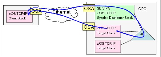
Figure E-9 Sysplex Distributor before RoCE
The traditional Sysplex Distributor has these characteristics:
•All traffic from the client to the target application goes through the Sysplex Distributor TCP/IP stack.
•All traffic from the target application goes directly back to the client using the TCP/IP routing table on the target TCP/IP stack.
Sysplex Distributor after RoCE
Figure E-10 shows a RoCE Sysplex Distributor:
•The initial connection request goes through the Sysplex Distributor stack.
•The session then flows directly between the client and the target over the RoCE cards.

Figure E-10 Sysplex Distributor after RoCE
|
Note: As with all RoCE communication, the session end also flows over OSAs.
|
E.3.3 Enabling SMC-R support in z/OS Communications Server
The following checklist provides a task summary for enabling SMC-R support in z/OS Communications Server. This list assumes that you start with an existing IP configuration for LAN access using OSD:
•HCD definitions (install and configure RNICs in the HCD):
– Add the PNetID for the current OSD.
– Define PFIDs for RoCE (with the same PNetID).
•Specify the GLOBALCONFIG SMCR parameter (TCP/IP Profile):
– Must specify at least one PCIe Function ID (PFID):
• A PFID represents a specific RNIC adapter.
• A maximum of 16 PFID values can be coded.
– Up to eight TCP/IP stacks can share a PFID in a specific LPAR.
•Start the IPAQENET or IPAQENET6 INTERFACE with CHPIDTYPE OSD:
– SMC-R is enabled, by default, for these interface types.
– SMC-R is not supported on any other interface types.
•Repeat in each host (at least two hosts).
Start the TCP/IP traffic and monitor it with NetStat and IBM VTAM displays.
..................Content has been hidden....................
You can't read the all page of ebook, please click here login for view all page.