CHAPTER 3
Port profiles
Port profiles (and logical switches) act as containers, essentially templates, for the properties and capabilities to be applied to network adapters. These tools allow you to consistently apply the same settings and capabilities to network adapters across multiple hosts. You can configure network adapter settings and capabilities on each host computer in your environment by making the necessary changes manually (or via Windows PowerShell), but if you've deployed Microsoft System Center 2012 SP1 Virtual Machine Manager (VMM), the recommended approach is use port profiles and logical switches to define the list of logical networks and the set of properties and capabilities you want to deploy.
This chapter will:
▪ Review the role of port profiles in a virtualized network solution
▪ Discuss the different types of port profiles and how they are used
▪ Explain how to identify the set of port profiles you need in your environment
▪ Discuss the use of port classifications to hide implementation details
Uplink port profiles
There are two types of port profiles in VMM: uplink port profiles and network adapter port profiles. Uplink port profiles are applied to physical network adapters as part of logical switch deployment and define the set of logical networks that should be associated with those network adapters. They also specify how multiple network adapters in a given host computer using the same uplink port profile should be teamed. Network adapter port profiles, in contrast, are applied to virtual network adapters and define specific capabilities such as bandwidth limitations, priority, security settings, and so on.
If you have a simple environment that consists of a single physical network in one location or a stretched or campus network with multiple physical locations, and if all host computers are configured the same way, have the same requirements, and use the same protocols for network adapter teaming, then a single uplink profile may be all you need in your environment. In practice, however, such an environment is rare outside of a small business or test lab, and even then, the need to scope or restrict certain logical networks to a specific group of host computers can lead you to create multiple uplink port profiles. A process for identifying how many uplink port profiles you need is outlined in the section, "How many uplink port profiles do you need?" later in this chapter.
Figure 3-1 illustrates the different layers in the architecture of a virtualized networking solution, showing uplink port profiles and their connections to other components of the architecture.
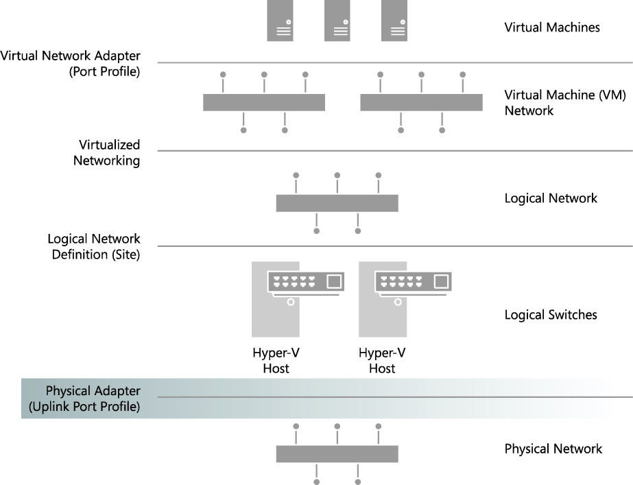
FIGURE 3-1 Position of uplink port profiles in the VMM network architecture.
What is defined in an uplink port profile?
An uplink port profile defines the load-balancing algorithm and the teaming mode that should be used by any of the physical network adapters on which it is applied, together with the set of logical networks that should be associated with those adapters. If you have host computers with differing requirements in terms of network adapter teaming, load balancing protocols, or you need to scope logical networks to a specific group of host computers, you will need to create separate uplink port profiles for each one of these combinations.
Load balancing and teaming protocols
You can choose a number of different teaming modes and load balancing algorithms when defining an uplink port profile. For example, Figure 3-2 shows the default teaming mode selections: HyperVPort for the load balancing algorithm, which distributes network traffic based on the Hyper-V switch port identifier of the source virtual machine, with SwitchIndependent defined for teaming mode, which specifies that (physical) network switch configuration is not required and hence allows network adapters (within the team) to be connected to multiple (non-trunked) physical switches. You can use these default selections or choose the settings and configuration that will be most appropriate for the hosts and network adapters on which the uplink port profile will be applied.

FIGURE 3-2 Load balancing and teaming mode selection in an uplink port profile.
MORE INFO You can find more detailed information on the different load balancing and traffic distribution options and teaming modes that can be defined in an uplink port profile at http://technet.microsoft.com/library/hh831648.aspx and in the LBFO whitepaper at http://www.microsoft.com/en-us/download/details.aspx?id=30160.
Network sites (logical networks)
Uplink port profiles also contain a list of network sites (otherwise known as logical network definitions), with each Network Site representing a link to a different logical network. When the uplink port profile is applied to a physical network adapter, for example as part of logical switch deployment, these network sites determine the set of logical networks that should be associated with the physical adapter and the VLANs and IP subnets that should be allocated to virtual machines (VMs) and services that connect to those logical networks.
For example, Figure 3-3 shows the list of network sites that are configured in the uplink port profile called Production - Reading. When this uplink port profile is applied to a physical network adapter as part of logical switch deployment (see Chapter 4, “Logical switches”), the Management, Tenant - VLAN Isolated and Tenant - PVLAN Isolated logical networks will be associated with that adapter. The VLANs and IP addresses for each logical network will be as defined in the respective network sites.
NOTE You should ensure that all network sites that will be included in a given uplink port profile are scoped to the same set (group) of host computers. Although no error is reported when you initially create the uplink, you will receive an out-of-scope error when you try to apply it (as part of logical switch deployment) to a computer that is not a member of the host groups defined in every one of the network sites included within the uplink.
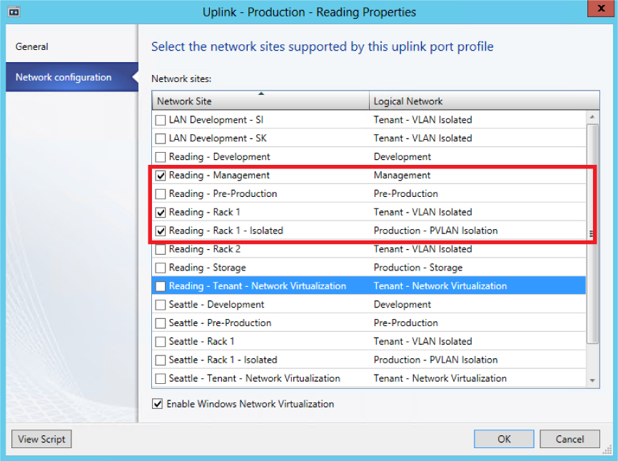
FIGURE 3-3 Network sites in an uplink port profile.
As the example in Figure 3-3 shows, it is reasonable for a VMM administrator to create an uplink port profile that contains references to multiple network sites (and, hence, logical networks). The key point is that the VLANs and IP addresses defined within each of the selected sites should all be valid (routable) from the physical Network Adapter that the port profile has been applied to. In the example in Figure 3-3, the VLANs and IP addresses defined in the Reading - Management, Reading - Rack 1 and Reading - Rack 1 - Isolated network sites are expected to be both valid and routable if applied to a host computer located in Rack 1 of the Reading datacenter.
You should try to ensure that each of the network sites that you add to an uplink port profile refer to a different logical network. The problem with doing otherwise basically is that all of the VLANs and IP subnets defined in those network sites will be associated with the logical network on any host computer on which the uplink port profile is applied. The problem, if you are not using VLAN isolation is that the host computer has no way to establish which of the range of possible VLANs and IP subnets will be needed to allow VMs connected to the logical network to communicate on the physical network and will pick randomly from the list of those available. As a consequence, some of the VMs may be allocated routable IP addresses, while others are not.
How are uplink port profiles used?
When a logical switch is applied to a network adapter in a Hyper-V host as shown in Figure 3-4, VMM uses the information contained in the logical switch and the selected uplink port profile to create a Hyper-V virtual switch on the host. The network sites referenced in the uplink port profile are used to determine which logical networks, VLAN, and IP subnets should be associated with that adapter.

FIGURE 3-4 Selecting an uplink port profile as part of logical switch deployment.
As you would expect, if the same logical switch and uplink port profile is applied to two or more adapters in a given host computer, those adapters will be teamed, assuming that this feature has been enabled in the selected logical switch. The teaming protocol used will be the one specified in the selected uplink port profile.
How many uplink port profiles do you need?
At least one uplink port profile needs to be created for you to be able to use logical switches (which were discussed in Chapter 4), but the following sections outline the process you should follow to identify uplink port profiles in your environment, look at some of the main reasons why you would (or would not) create an uplink port profile, and provide an overview of the key considerations, best practice guidance, and key recommendations.
1. You need at least one uplink port profile for each physical network that exists within your environment.
2. For each of these networks, you need to define uplinks for each physical location that has its own VLAN and IP subnets.
3. If you plan to restrict or otherwise scope logical networks to a specific set of host computers, you will need to create uplinks for each group of computers.
4. You need separate uplink port profiles for groups of computers (in each physical location) that have different connectivity requirements or use different teaming protocols.
5. Finally, you might consider creating separate uplinks for networks that do not or will not support network virtualization.
As the list suggests, you will need a significant number of uplink port profiles in complex environments, so you should also consider a naming convention because a good naming convention can help promote understanding as well as simplify management, as discussed later in this chapter.
Multiple physical networks
Networks are introduced into an environment for many different reasons, but security and isolation are the most common reasons. Service providers (hosters) like Contoso may decide to use physical networks to separate tenant workloads from internal (corporate) workloads, for example, but the requirement to provide specific performance guarantees for certain types of network traffic or to mitigate potential network congestion may necessitate the use of separate physical networks.
The trend today is toward converged networking, which minimizes the need for separate physical networks even where traffic isolation and specific service levels are required for different types of network traffic. In a converged network, logical networks separate different types of network traffic on the physical network, and Quality of Service (QoS) policies ensure that each type of traffic is given the required prioritization and bandwidth.
With that said, regardless of whether you have adopted a converged networking solution, the process to determine how many uplink port profiles to create is the same. Uplink port profiles contain a list of network sites and, as discussed in Chapter 2, “Logical networks,” network sites define the VLANs and IP subnets that are associated with a logical network in each physical location. Since each physical network (in a routed network) will have its own set of VLANs and IP subnets, it follows that at least one network site will need to be defined for each physical network.
The question is can all of these network sites can be combined in a single uplink port profile or will multiple uplink port profiles be required. To answer this question, consider what happens when an uplink port profile is applied to a network adapter in a host computer as part of logical switch deployment. Essentially, the network sites listed in the uplink port profile are used to determine which logical networks should be associated with the network adapter and the VLANs and subnets that should be used by VMs and services that use that adapter to connect to the physical network.
If you were to define and use a single uplink port profile, all of the possible VLANs and IP subnets linked to a given logical network would be associated with the physical network adapter on which that profile was applied. This is clearly not an ideal situation and you should assume at least one uplink port profile will be required for each physical network that is routed (not bridged) to other internal or external networks.
Recall that Contoso, the example organization from Chapter 2, has three physical networks: all corporate (internal) workloads and services are hosted on the Datacenter network; storage devices are accessed via the Storage network, and customer (tenant) network traffic is on the Provider network. Leaving aside that Contoso has more than one physical location, a minimum of three uplink port profiles would be required to support this environment (see Figure 3-5).

FIGURE 3-5 One uplink port profile for each physical network.
Another reason to consider separate uplinks for each physical network is the scope of the logical networks you identified as part of the process discussed in Chapter 2. Although technically possible, it is difficult to identify a scenario in which a given logical network would need to be hosted on multiple physical networks. You would normally find multiple logical networks associated with a single physical network since this approach allows an administrator to separate computers and network services (on that network) with different business purposes, isolate certain types and groups of network traffic, and support workloads with differing QoS requirements and expected bandwidth.
Multiple physical locations
Having determined that at least one uplink port profile is required for each physical network, you can now consider and explore a more realistic network scenario, one in which each physical network is divided into different sites to minimize broadcast traffic and to optimize performance, with routers used to facilitate inter-site communication. In this scenario, each network site has unique VLANs and IP subnets, and virtual machines or services hosted in a given site will need to be provided with VLAN IDs and IP addresses that are both valid and routable within that site in order to communicate.
At Contoso, for example, Hyper-V hosts connected to the Datacenter network are situated in two physical locations, Reading and Seattle, with each of these locations allocated a different set of VLANs and IP subnets. Within each site, VLANs and IP subnets are used to separate different types of workload and help ensure QoS. At present, virtual machines and services running development workloads are based only in Reading and use VLAN 15 and subnet 192.170.15.0/24, while production workloads are supported in both datacenters. In Reading, production workloads use VLAN18 and have an IP address in the 192.168.99.0/24 subnet, while those running production workloads in Seattle use VLAN 100 and have an IP address in the 192.168.199.0/24 subnet, as shown in Figure 3-6.

FIGURE 3-6 Workloads differentiated by VLAN and IP subnet.
Since development activities are performed only in Reading, only a single network site called Reading-Development is needed to define the VLANs and IP subnets that are to be associated with the Development logical network. To support the Production logical network in multiple locations, however, two network sites are required, one for Reading and one for Seattle, as shown in Figure 3-7, since each of these locations requires a different VLAN and IP subnet for production workloads.

FIGURE 3-7 Network sites in a logical network.
Having defined network sites for the logical networks that exist within your environment according to the guidelines set out in Chapter 2, you can begin to allocate those sites to uplink port profiles. Since putting all of these network sites into a single uplink port profile means that all of the possible VLANs and IP subnets linked to a given logical network would be associated with the physical network adapter on which that uplink profile was applied, it follows that multiple physical sites with their own set of VLANs and IP addresses, as in the Contoso example, will need a separate uplink port profile defined for each physical location.
NOTE For the purposes of this discussion, multiple physical sites that are effectively linked together in a campus network or a stretched physical network operating across a number of different physical sites can be considered a single physical location.
Multiple network sites, each one representing a different logical network, can be combined in the same uplink profile assuming that all of the VLANs and IP subnets defined in those network sites are valid (and routable) on any host computer on which the uplink port profile is applied. Note that all of the logical networks (referenced by the selected network sites) will also be made available on each of these hosts. If you want to scope or otherwise restrict which host computers are associated with a given logical network, you will need to create additional uplink port profiles
In the Contoso example, both the Production and Development logical networks are to be made available in Reading. Assuming that in this simple environment, all hosts in this location have the same network adapter teaming and connectivity requirements and there are no issues with those hosts being associated with both of these logical networks, a single uplink port profile for Reading, referencing the Reading-Development and Reading-Production network sites, is sufficient. Since there is no requirement to support the Development logical network in Seattle, the uplink port profile for that location will contain only a single Network Site, Seattle-Production (see Figure 3-8).

FIGURE 3-8 Defining uplink port profiles for each physical site.
After identifying the sites and therefore the initial set of uplink port profiles required for one of the physical networks in your environment, repeat the process for each of the others. In the Contoso example, having determined the set of uplinks required for the Datacenter network, which supports internal (corporate) workloads, the administrator would next follow the same process for the Storage and Provider networks.
Restricting the scope of logical networks
To this point, this discussion has assumed that there are no business or technical reasons to restrict the set of logical networks to be included in a given uplink port profile. Yet, within each physical site, it is fairly common to find groups of host computers set aside (dedicated) to a specific purpose or type of workload (see Figure 3-9). In an enterprise environment, for example, the most powerful and generally the most expensive hosts are dedicated to running production workloads. At a service provider like Contoso, host computers run workloads for or on behalf of multiple external customers (shared compute model), while other hosts are allocated to and run workloads for a single customer only (dedicated compute model).

FIGURE 3-9 Associating logical networks with dedicated servers.
How does this knowledge and the introduction of dedicated host computers into physical locations influence the approach to uplink port profiles? It is quite possible, as discussed earlier, to create an uplink port profile that contains multiple network sites, each of which represents a different logical network. The issue with such an approach is that all of the logical networks that are referenced in the uplink port profile will be associated with the host computers on which the uplink port profile is applied. In the dedicated compute model, shown in Figure 3-9, this is not appropriate. Contoso wants to make sure, for example, that only those hosts dedicated to production workloads are associated with the Production logical network. Therefore, to restrict or otherwise limit the set of host computers (within a physical site) that should be associated with specific logical networks, you will need to create a separate uplink port profile for those hosts.
Note that some logical networks, such as Management, Storage, Backup, and Live Migration for example, are generally common across all systems regardless of the workload they have been dedicated to. Since it is possible to include network sites for multiple logical networks in a single uplink port profile as long as the VLAN and IP subnets defined in these sites are valid within a particular physical location, you may choose to include these in your dedicated uplink port profile. You could also create a separate uplink port profile for common logical networks (within in a particular location) if you prefer. In the latter case, your host computers will require a dedicated physical network adapter on which you can apply this additional uplink port profile.
Contoso has three different types of workloads running in Reading, development, pre-production, and production, and for operational reasons, the company has decided to place each one of these different workloads onto a separate (dedicated) group of host computers. Host computers should be associated with both a workload-specific logical network (such as Development) and the logical network required for host management, which is common to all three.
To support this environment, three uplink port profiles will be required, one for each group of dedicated computers, as mentioned earlier. Each of the three uplink port profiles will contain two network sites: one from the logical network specific to the type of workload (Reading-Development, for example) and the other from the Management logical network (Reading-Management, in this case), which is required on all hosts within Reading regardless of workload (see Figure 3-10).

FIGURE 3-10 Define uplink port profiles for dedicated resources.
NOTE Although multiple logical networks may associated with a host network adapter using a single uplink port profile, each of these networks will be isolated from each other. If you wish to allow virtual machines and services on one logical network to communicate with those connected to another, you will need to use a router or gateway device.
In each physical location, computers dedicated to specific workloads will normally be able to communicate with each other without the need for traffic routing, but in some environments, this is not the case for various reasons, including scale (insufficient IP addresses available in a given subnet), performance, and the need to manage broadcast traffic. It may therefore be necessary to place these host computers in different (routed) IP subnets.
At Contoso, for example, host computers dedicated to running production workloads in the Reading datacenter are located in one of three racks, with each rack allocated its own VLAN and IP subnet to allow the solution to scale. A router allows host computers, virtual machines, and services in one rack to communicate with any of the others. To support this environment, three network sites will need to be created in VMM for the Production logical network (in Reading), one for each rack, as shown in Figure 3-11, with additional network sites added as the solution scales above these three initial racks.

FIGURE 3-11 Multiple network sites in the same physical location.
NOTE In addition to those created for the Production logical network, it will be necessary to define network sites (one per rack) for any other logical networks that need to be associated with host computers located in these racks.
Because all three of these network sites cannot be placed into a single uplink port profile since doing so means that all of the VLANs and IP subnets linked to the Production logical network would be associated with any physical network adapter on which the uplink profile was applied, which is clearly not desirable. It therefore follows that if you have a group of host computers within a physical location that have their own set of VLANs and IP addresses and use a switch or router to communicate with other resources on the network, as in the Contoso example, then you will need to define uplink port profiles for host computers (within a site) that are on a separate routed subnet.
Returning to the Contoso example, there are now three separate network sites for the Production and Management logical networks in the Reading datacenter. These cannot be combined into a single uplink port profile for the reasons mentioned above, so individual uplink port profiles must be created for each rack, as shown in Figure 3-12.

FIGURE 3-12 Uplink port profiles for sites within physical location.
If you set aside host computers for specific workloads, projects, or tenants, you clearly do not want to permit someone to inadvertently apply an uplink port profile designed for host computers running production workloads to a host used only for development (Reading -Production (Rack1) in the example.
Unfortunately, there is no such thing as security groups or scoping for uplink port profiles. You can address this limitation, however, by including within your uplink port profile network sites that are scoped (restricted) to host computers that are members of a particular host group, as outlined in Chapter 2. Note that the scope of all of the network sites in a particular uplink port profile must be identical. If they are not, you may receive an out-of-scope error when you try to apply the uplink port profile (as part of logical switch deployment) to a computer that does not fit into the host groups used by all of the network sites referenced within the uplink.
Different connectivity requirements
After determining the initial set of uplink port profiles to be created for each group of host computers at a given physical location, the next step is to look at how each of these computers is physically connected to the network. In a Software Defined Network (SDN), all hosts would be configured the same, all would have the same set of network adapters, all network traffic would co-exist on the same physical network, and logical networks and QoS policies would be used to differentiate and prioritize different types of traffic. In such an environment, known as a fully converged network, your original set of uplink port profiles may require little or no further refinement, as illustrated in Figure 3-13.

FIGURE 3-13 Uplink port profile assignment in a fully converged network.
In most environments, however, host computers are not all connected to the network in the same way. For example, connectivity often varies according to the role and type of workload expected to run on the host. Even in the same host computer, network adapters may be dedicated to specific functions like storage, host management, or tenant traffic, each of which may require different teaming modes and load balancing algorithms. Hosts may even contain a mixture of standard and specialist network capabilities, such as RDMA and SR-IOV, which need to be managed differently. In the case of RDMA and SR-IOV, for example, network workloads are offloaded to the physical network adapter there bypassing the networking stack, and so it is not possible for the adapter team (which is part of the networking stack) to look at or redirect the data to another path.
NOTE VMM does not specifically recognize an RDMA network adapter installed in a host computer, and there are no settings or configuration in VMM for RDMA. If you are using RDMA network adapters, you should not create uplink port profiles or deploy a logical switch on these adapters.
Based on these considerations, you will likely need to refine your original list of uplink port profiles by creating additional uplink port profiles to associate logical networks with specific network adapters that optimize around workload and connectivity to the physical network.
At Contoso, for example, the majority of host computers in Rack 1 of the Reading datacenter have eight physical network adapters, with two dedicated to host management, four dedicated to storage, and the remaining two used by guest VMs. The adapter teaming and load balancing requirements for each of these different types of workload are very different. For example, the network adapters configured for storage in this environment are using LACP teaming to optimize around Contoso’s use of SMB v3 and Multi-Path IO, while the SR-IOV adapters used by guest VMs do not support teaming due to the way these adapters operate.
Because a single uplink port profile will not work for this group of host computers additional uplink port profiles must be created to take account of the different connectivity requirements. Furthermore, since workloads like storage, backup, and live migration will not be present on all of the network adapters in a host (as in the converged network model), they will be present only on those adapters that have been allocated and optimized for that type of workload.
The diagram in Figure 3-14 shows the result of this optimization around connectivity. Instead of a single uplink port profile for Rack 1, there are now three, one for each different group of network adapters in the host, and instead of including network sites for all logical networks that apply to production systems, the new uplink port profiles contain only those that are relevant to the workloads that will be carried on those adapters.

FIGURE 3-14 Identifying the need for uplinks based on connectivity.
Host computers dedicated to specific tasks and workloads often have different requirements in terms of connectivity to other hosts in the datacenter, even when they are connected to the same networks or reside in the same rack. In each case, you need to review the type of network adapters in each host to determine if they require any special attention, creating new uplink port profiles (as discussed) where it make sense to do so.
Disabling Network Virtualization
Having refined the uplink port profile design, you may find a number of uplink port profiles contain network sites for logical networks that are used only by the host or that are required to manage the host. In such cases, it may be useful to clear the Enable Windows Network Virtualization option (shown in Figure 3-15) Deselecting the Enable Windows Network Virtualization option provides a useful scoping mechanism, helping to clarify which uplinks are designed primarily for infrastructure services and host management and which are designed for use by end user VMs.

FIGURE 3-15 Disabling Network Virtualization in an uplink port profile.
With that said, since Network Virtualization service adds very little overhead to the host, it may be preferable to leave this setting on even in uplink port profiles that contain only infrastructure services, just for consistency. You can instead disable Network Virtualization at the logical network layer (shown in Figure 3-16).
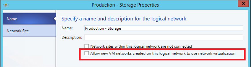
FIGURE 3-16 Disabling Network Virtualization in the logical network layer.
Ultimately, the choice of where to disable Network Virtualization comes down to whether you have uplink port profiles dedicated to management and infrastructure, in which case, either approach will be satisfactory. If, on the other hand, some uplink port profiles contain network sites from a mixture of infrastructure, management, and tenant or end user logical networks, the only option is to leave the Network Virtualization option enabled in the uplink port profile and disable it on those logical networks used for management and infrastructure.
Naming conventions
In complex multi-site environments, with multiple logical and physical networks and specialist host computers that have differing requirements in terms of connectivity and network adapter teaming, you can quickly build up a significant number of uplink port profiles. Without a sound naming convention, it can become difficult to determine which uplinks should be applied to which network adapters in a given host during logical switch deployment.
A naming convention like the following can help administrators clearly identify the scope and purpose of a given uplink and reduce management costs. Adding a high level description to aid understanding is strongly recommended.
[Location] - [Group] (Racknn) - [Connectivity]
Where typical examples of this structure would be:
Reading - Production (Rack1) - LACP
Reading - Production (Rack1) - SRIOV
Reading - Development - NoTeam
This particular structure may be too detailed or complex for your specific environment, but the point is you need to arrive at a convention that clearly identifies the different uplink port profiles you have created and what they are used for.
Network adapter port profiles
Network adapter port profiles can be applied to network adapters defined within a guest VM or virtual network interface cards (vNICs) that are created within a logical switch deployed on a host computer. They define the processor offload settings that should be used (assuming that the physical hardware on which the virtual adapter is deployed is able to support those capabilities), the security settings that should be applied, and how outgoing network bandwidth should be controlled and managed.
Unlike uplink port profiles, a number of example network adapter port profiles are provided out of the box. In practice, outside of a relatively small environment, it’s likely that you will need to add to and refine this initial list to meet your specific requirements. A simple process to help you determine how many of these profiles you actually need is outlined later in this chapter.
It’s important to note that users do not have direct access to network adapter port profiles. Instead, the user (and administrator in the case of a vNIC) selects a logical switch and then a port classification within that switch for each adapter’s connection to the network. The selected classification is essentially mapped to one of the network adapter port profiles that is available within the selected logical switch.
The diagram in Figure 3-17 illustrates the different layers that make up the architecture of a virtualized networking solution, highlighting where network adapter port profiles connect to other components of the architecture. Although not shown in the diagram, network adapter port profiles can also be applied to vNICs, but only when the vNIC is associated with a VM network that is not enabled for Network Virtualization (see Chapter 2 for more details).

FIGURE 3-17 Architecture showing network adapter port profiles.
What is defined in a network adapter port profile?
Network adapter port profiles define the processor offload settings, security settings, and bandwidth limitations to be enforced on network adapters within a guest VM or virtual network interface cards (vNICs) on which they are applied. You can find more detail on the range of different settings and capabilities that can be configured within one of these profiles on TechNet at http://technet.microsoft.com/en-us/library/jj721570.aspx.
If groups of host computers within your environment have differing requirements with respect to any of these settings and capabilities, you should consider separating network adapter port profiles for each different combination. This topic is covered in more detail later in the chapter.
How are network adapter port profiles used?
As mentioned earlier, users (and administrators in the case of vNICs) do not interact with network adapter port profiles directly. To connect a VM network adapter to a VM network, the user selects a logical switch and, optionally, a port classification from the list of those available within the selected switch. The port classification (or the default if none is chosen by the user) maps to one of the network adapter port profiles within the same switch. The settings and capabilities in this mapped port profile are then applied to the virtual network adapter.
In the example shown in Figure 3-18, the Reading-Production logical switch contains a number of network adapter port profiles and port classifications. One of the network adapters in virtual machine WEBSVR-001 is connected to the Corporate VM network through this logical switch. Because the High Bandwidth port classification has been selected and is mapped (within the logical switch) to the High Bandwidth network adapter port profile,, outbound network traffic on network adapter 1 would include the IEEE priority tag and to be allocated a minimum bandwidth weight of 10.

FIGURE 3-18 Applying a network adapter port profile.
The port classification is simply a label. The end users have no insight into which network adapter port profile has been mapped to any of the port classifications they have access to or the different settings and capabilities that are defined within the port profile they choose to apply to their VMs.
How many network adapter port profiles do you need?
Multiple network adapter port profiles are required whenever your environment contains physical and virtual computers with differing QoS requirements, essentially the need to provide certain guarantees for outgoing network bandwidth and security policy, or when specialist network adapters (e.g., SR-IOV) that require additional configuration with VMM have been deployed.
Although a number of sample network adapter port profiles are provided out of the box, in practice, business requirements such as the need to enforce different security settings or ensure that certain workloads are prioritized above others likely require you to update and refine the settings and capabilities within this initial set of profiles and to create additional ones.
The following process will help you decide whether to create new network adapter profiles in your environment and outlines some best practice guidance and key recommendations:
1. First, identify and build network adapter port profiles for workloads that need a guaranteed QoS, essentially where you need to control and manage outgoing network bandwidth.
2. Add additional network adapter port profiles to support VM networks that have different security requirements.
3. Finally, add network adapter port profiles for any physical network adapters that support either IPSec Task Offloading, SR-IOV, or Virtual Machine Queue (VMQ) processor offload capabilities.
As with the other components of your virtual networking architecture, after you have identified the required set of network adapter port profiles, you should identify a formal naming convention to help promote understanding.
Quality of Service
In a converged network, network traffic from a mixture of different workload types co-exist on and share the same physical network with QoS policies used to ensure network traffic related to the most important workloads, like production for example, will be prioritized above any of those considered of lesser importance. This distinction can help you to define your initial set of network adapter port profiles, one for each different priority (or weighting) value.
At Contoso, a number of different types of workload have been identified, as shown in Figure 3-19, with each one allocated a relative weighting or minimum bandwidth weight. Management and Cluster Heartbeat share the same value and are ranked highest in the list since these are required to keep the environment up and running. Live Migration and Production workloads follow in terms of relative priority. Network traffic related to development is viewed as the least important, at least in this ranking, and has the lowest bandwidth weight. A separate network adapter port profile should be created for each group of workloads with the same relative rating.

FIGURE 3-19 A network adapter port profile for each prioritized workload.
Instead of allocating relative values to particular workloads, you can use the minimum and maximum bandwidth (in Mb) settings within the network adapter port profile to define specific thresholds for each workload type. This approach may provide more granular control, but relative priority is recommended since it allows you to make use of all available bandwidth.
NOTE A given logical switch will be in either Relative Weights or Absolute Bandwidth Values mode with respect to bandwidth control. The default is Relative Weights. If some workloads will use relative weights and others will use fixed bandwidth limits, you need to create separate network adapter port profiles for each type of workload and ensure that the network adapter port profiles contained within a given logical switch match and align with the bandwidth control mode that has been defined for that switch. See Chapter 4 for more information on logical switches.
Security settings
After creating an initial set of network adapter port profiles based on workload type and the priority of those workloads relative to others, the next step is to consider security settings. In general, most of the VMs and services that use a particular network adapter port profile will have the same general requirements in terms of network security, and in these cases, no further refinement to your solution is required since the appropriate security settings can be enabled in the selected port profile.
If, however, certain VMs and services within a given workload require different security settings, you will need to create a new network adapter port profile. The new profile will be identical in terms of bandwidth control since the underlying workloads are unchanged, but will contain the new security settings and configuration.
At Contoso, for example, most systems in production do not use or require support for guest teaming, so this security setting has been purposely disabled in the Production-Secure network adapter port profile. This security setting is clearly inappropriate for applications and services in Production that rely on teamed in-guest network adapters for performance reasons, so a new network adapter port profile has been introduced, Production-Scale Out, to support this specific requirement. For similar reasons, a third port profile, Production-Tenant Interface, has been created for front-line production VMs on which MAC Spoofing needs to be enabled (see Figure 3-20).

FIGURE 3-20 Refined solution for workloads with different security settings.
Having identified the range of security settings required for one type of workload, you should review each of the others and repeat the process, creating additional network adapter port profiles as you identify different security requirements.
Support for processor offloading
In the final step, you optimize the set of port profiles for host computers containing physical network adapters that support either IPsec Task Offloading, SR-IOV, or VMQ. As before, if workloads that use a given network adapter port profile will be deployed only on host computers that have the same capabilities with respect to processor offload settings, then no further refinement is required; the appropriate settings may be made in the selected port profile.
If, however, a given workload, such as Production, will run on hosts with a mixture of different processor offload capabilities, you will need to create a new network adapter port profile for each type. The new profile will be identical in terms of bandwidth control and security settings; the only difference will be the processor offload configuration.
At Contoso, for example, most systems in production do not use or require support for SR-IOV, so this capability has been purposely disabled in the Production-Secure-Standard network adapter port profile (see Figure 3-21). This port profile is clearly inappropriate for applications and services in production that use this feature, so a new network adapter port profile has been introduced, Production-Secure-SR-IOV, that supports this specific requirement.

FIGURE 3-21 Adding profiles for network adapters that support offloading.
NOTE Enabling support in the network adapter port profile may not be sufficient for certain processor offload modes. It may be necessary to make changes in multiple places within the virtual network architecture, including in the physical host, the logical switch, and the uplink port profile, for this to work successfully, as is the case with SR-IOV.
Naming conventions
It is likely that compared to some of the other objects covered so far, you will find that you need relatively few network adapter port profiles even in the largest of environments. But as with all things, it is still useful to develop a sound naming convention. The following convention below is a good starting point since it helps administrators clearly identify the scope and purpose of a given port profile. Adding a high level description to aid understanding is strongly recommended.
[Workload] - [Security] - [Connectivity]
Where typical examples of this structure would be:
Infrastructure
Production - Secure
Production - Secure - SR-IOV
Development
Test
This particular structure may be too detailed or complex for your specific environment. but the point is you need to arrive at a convention that clearly identifies the different network adapter port profiles you have created and what they are used for.