After Graphics, Pen and Brush are the two most important graphics classes. Whenever you perform any drawing operation that does not manipulate an image's pixels directly, you use a Pen or a Brush.
This chapter describes the Pen and Brush classes in detail. It shows how to use these classes to draw and fill all sorts of interesting shapes.
This chapter also describes the GraphicsPath class that represents a series of lines, shapes, curves, and text. You can fill a GraphicsPath using Pen and Brush classes.
The Pen object determines how lines are drawn. It determines the lines' color, thickness, dash style, join style, and end cap style.
A program can explicitly create Pen objects, but often it can simply use one of the more than 280 pens that are predefined by the Pens class. For example, the following code draws a rectangle using a hot pink line that's one pixel wide:
gr.DrawRectangle(Pens.HotPink, 10, 10, 50, 50)
Pen objects are scaled by transformations applied to a Graphics object, however, so the result is not necessarily one pixel thick. If the Graphics object applies a transformation that scales by a factor of 10, the resulting line will have thickness 10.
One solution to this problem is to create a new Pen object setting its thickness to 0.1, as shown in the following code. The thickness is scaled to 0.1 * 10 = 1.
gr.DrawRectangle(New Pen(Color.HotPink, 0.1), 10, 10, 50, 50)
Another solution is to create a pen with thickness 0. The GDI + routines always draw lines that have 0 thickness as one pixel wide.
The Pen class provides several overloaded constructors, which are described in the following table.
CONSTRUCTORS | DESCRIPTION |
|---|---|
| Creates a pen of thickness 1 using the indicated Brush. Lines are drawn as rectangles filled with the Brush. This makes the most sense for relatively thick lines, so the fill is visible. It produces sometimes irregular dashed or dotted results for thin lines. |
| Creates a pen of thickness 1 using the indicated color. |
| Creates a pen with the indicated thickness (a Single) using a Brush. |
| Creates a pen with the indicated thickness (a Single) using the indicated color. |
The following table describes some of the Pen class's most useful properties and methods.
PROPERTY OR METHOD | PURPOSE |
|---|---|
| Determines whether the line is drawn inside or centered on the theoretical perfectly thin line specified by the drawing routine. See the section "Alignment" later in this chapter for examples. |
| Determines the Brush used to fill lines. |
| Determines the lines' color. |
| Lets you draw lines that are striped lengthwise. See the section "CompoundArray" later in this chapter for examples. |
| Determines the line's end cap. See the section "Custom Line Caps" later in this chapter for examples. |
| Determines the line's start cap. See the section "Custom Line Caps" later in this chapter for examples. |
| Determines the cap drawn at the ends of dashes. This can be Flat, Round, or Triangle. |
| Determines the distance from the start of the line to the start of the first dash. |
| An array of Singles that specifies a custom dash pattern. The array entries tell how many pixels to draw, skip, draw, skip, and so forth. Note that these values are scaled if the pen is not one pixel wide. |
| Determines the line's dash style. This value can be Dash, DashDot, DashDotDot, Dot, Solid, or Custom. If you set the DashPattern property, this value is set to Custom. Note that the dashes and gaps between them are scaled if the pen is not one pixel wide. |
| Determines the cap used at the end of the line. This value can be ArrowAnchor, DiamondAnchor, Flat, NoAnchor, Round, RoundAnchor, Square, SquareAnchor, Triangle, and Custom. If LineCap is Custom, you should use a CustomLineCap object to define the cap. Figure 30-1 in Chapter 30 shows the standard LineCap values. |
| Determines how lines are joined by a GDI+ method that draws connected lines. For example, the DrawPolygon and DrawLines methods use this property. This value can be Bevel, Miter, and Round. Figure 30-2 in Chapter 30 shows these values. |
| Multiplies the Pen class's current transformation by another transformation matrix. See the section "Pen Transformations" later in this chapter for more information and examples. |
| Resets the Pen class's transformation to the identity transformation. See the section "Pen Transformations" later in this chapter for more information and examples. |
| Adds a rotation transformation to the Pen class's current transformation. See the section "Pen Transformations" later in this chapter for more information and examples. |
| Adds a scaling transformation to the Pen class's current transformation. See the section "Pen Transformations" later in this chapter for more information and examples. |
| This method takes parameters that let you specify the Pen class's StartCap, EndCap, and LineJoin properties at the same time. |
| Determines the cap used at the start of the line. See the EndCap property for details. |
| Determines the transformation applied to the initially circular "pen tip" used to draw lines. The transformation lets you draw with an elliptical tip. See the section "Pen Transformations" later in this chapter for more information and examples. |
| Adds a translation transformation to the Pen class's current transformation. Pen objects ignore any translation component in their transformations, so this method has no effect on the Pen class's final appearance and was probably added for consistency and completeness. See the section "Pen Transformations" later in this chapter for more information and examples. |
| The width of the pen. This value is scaled if the pen is transformed either by its own transformation or by the transformation of the Graphics object that uses it. |
The following sections describe some of the Pen class's more confusing properties and methods.
The Alignment property determines whether thick lines for closed curves are drawn inside or centered on the theoretical perfectly thin line specified by the drawing routine. This property can take the values Center or Inset.
The following code draws a circle with a thick white line and its pen's Alignment set to Center. It then draws the same circle with a thin black line. Next, the code repeats these steps, drawing its thick white circle with Alignment set to Inset.
Private Sub Form1_Paint(ByVal sender As Object,
 ByVal e As System.Windows.Forms.PaintEventArgs) Handles MyBase.Paint
    Using the_pen As New Pen(Color.LightGray, 20)
        the_pen.Alignment = PenAlignment.Center
        e.Graphics.DrawEllipse(the_pen, 25, 25, 100, 100)
        e.Graphics.DrawEllipse(Pens.Black, 25, 25, 100, 100)

        the_pen.Alignment = PenAlignment.Inset
        e.Graphics.DrawEllipse(the_pen, 150, 25, 100, 100)
        e.Graphics.DrawEllipse(Pens.Black, 150, 25, 100, 100)
    End Using
End Sub
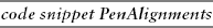
Figure 31-1 shows a more elaborate program that draws samples of all of the Alignment values. Notice that all of the Alignment values produce the same result as Center, except for the value Inset.
The Alignment property applies only to closed figures such as ellipses, rectangles, and polygons. Open figures such as line segments, arcs, and unclosed curves are always drawn centered.
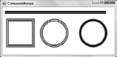
The CompoundArray property lets a program draw lines that are striped lengthwise. This property is an array of Single values that determine where the solid and empty parts of the line lie as a fraction of the line's width. For example, an array containing the values {0.0, 0.25, 0.75, 1.0} makes the first quarter of the line solid (0.0–0.25), the next half of the line not drawn (0.25–0.75), and the last quarter of the line solid (0.75–1.0).
The following code demonstrates the CompoundArray property. It creates a thick pen, sets its CompoundArray property to draw a line with a thin empty stripe down the middle, and draws a line. Next, the code sets the CompoundArray property to draw three equally sized and spaced stripes, and draws a rectangle and circle. Finally, the code sets the Graphics object's SmoothingMode property to AntiAlias, resets CompoundArray to draw a line with two thin empty stripes, and draws another circle.
Private Sub Form1_Paint(ByVal sender As Object,
 ByVal e As System.Windows.Forms.PaintEventArgs) Handles MyBase.Paint
    e.Graphics.SmoothingMode = Drawing2D.SmoothingMode.AntiAlias

    Using the_pen As New Pen(Color.Black, 10)
        the_pen.CompoundArray = New Single() {0.0, 0.45, 0.55, 1.0}
        e.Graphics.DrawLine(the_pen, 10, 20, 400, 20)

        the_pen.CompoundArray = New Single() {0.0, 0.2, 0.4, 0.6, 0.8, 1.0}
        e.Graphics.DrawRectangle(the_pen, 20, 50, 100, 100)
        e.Graphics.DrawEllipse(the_pen, 150, 50, 100, 100)

        the_pen.CompoundArray = New Single() {0.0, 0.1, 0.2, 0.8, 0.9, 1.0}
        e.Graphics.SmoothingMode = Drawing2D.SmoothingMode.AntiAlias
        e.Graphics.DrawEllipse(the_pen, 300, 50, 100, 100)
    End Using
End Sub
Figure 31-2 shows the result.
The Pen class's CustomEndCap and CustomStartCap properties let you define your own end caps for lines. To make a custom cap, make a GraphicsPath object that defines the cap's drawing commands. This object should use a coordinate system where X increases to the left of the line, and Y increases in the direction of the line, as shown in Figure 31-3.
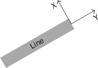
Figure 31.3. When building a custom line cap, X increases to the line's left and Y increases in the line's direction.
Next, create a CustomLineCap object, passing its constructor the GraphicsPath object. Pass the GraphicsPath as the first parameter if it defines a fill for the cap. Pass it as the second parameter if it defines drawn lines for the cap. Pass Nothing for the other parameter.
You can use the CustomLineCap object's properties and methods to modify its appearance. For example, its StrokeJoin property determines the style used to join the lines in the GraphicsPath, and its SetStrokeCaps method lets you specify the end caps for the lines in the GraphicsPath.
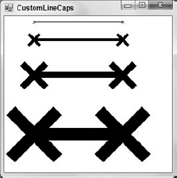
The following code shows an example. It defines an array of points that defines lines that make an X. It makes a GraphicsPath object and uses its AddLines method to add the lines to it. It then creates a CustomLineCap object, passing its constructor this GraphicsPath. The code makes a Pen and sets its CustomStartCap and CustomEndCap properties to the CustomLineCap object. It then draws four lines with different widths.
Private Sub Form1_Paint(ByVal sender As Object,
 ByVal e As System.Windows.Forms.PaintEventArgs) Handles MyBase.Paint
    ' Make a GraphicsPath that draws an X.
    Dim pts() As Point = {
        New Point(−2, −2),
        New Point(0, 0),
        New Point(−2, 2),
        New Point(0, 0),
        New Point(2, 2),
        New Point(0, 0),
        New Point(2, −2)
    }

    Using cap_path As New GraphicsPath
    cap_path.AddLines(pts)

    ' Make the CustomLineCap.
    Using x_cap As New CustomLineCap(Nothing, cap_path)
        ' Draw some lines with x_cap.
        Using the_pen As New Pen(Color.Black, 1)
            the_pen.CustomStartCap = x_cap
the_pen.CustomEndCap = x_cap
e.Graphics.DrawLine(the_pen, 50, 10, 200, 10)
the_pen.Width = 5
e.Graphics.DrawLine(the_pen, 50, 40, 200, 40)
the_pen.Width = 10
e.Graphics.DrawLine(the_pen, 50, 100, 200, 100)
the_pen.Width = 20
e.Graphics.DrawLine(the_pen, 50, 200, 200, 200)
End Using
End Using
End Sub
Figure 31-4 shows the result.
The Pen class has properties and methods that let you define a transformation. The Pen class applies this transformation to its initially circular tip when drawing lines. (For basic information on transformations, see the section "Transformation Basics" in Chapter 30, "Drawing Basics.")
The Pen class ignores any translation component in the transformation, so the result is always an ellipse. (With some thought, you can probably convince yourself that any combination of scaling and rotation applied to a circle always gives an ellipse.) When the program draws with the transformed pen, its lines may have thick and thin elements similar to the ones you get when you draw with a calligraphy pen.
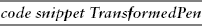
The following code uses a transformed Pen to draw a circle. It begins by defining some constants to make working with the circle easier. It defines the circle's center (Cx, Cy) and its radius R. It also defines a constant to represent the Pen's Width. Next, the program creates a new Pen with the desired width. It applies a scaling transformation to the pen, scaling by a factor of 4 in the Y direction. For the purposes of scaling Pens, the X and Y directions match those on the screen. This transformation stretches the Pen class's tip vertically on the screen. Next, the program rotates the Pen's tip by 45 degrees.
Private Sub Form1_Paint(ByVal sender As Object,
 ByVal e As System.Windows.Forms.PaintEventArgs) Handles MyBase.Paint
    Const Cx As Integer = 120
    Const Cy As Integer = 120
    Const R As Integer = 100
    Const PEN_WID As Integer = 10

    ' Draw a circle with a transformed Pen.
    Using the_pen As New Pen(Color.Black, PEN_WID)
the_pen.ScaleTransform(1, 4, MatrixOrder.Append)
the_pen.RotateTransform(45, MatrixOrder.Append)
e.Graphics.SmoothingMode = SmoothingMode.AntiAlias
e.Graphics.DrawEllipse(the_pen, Cx - R, Cx - R, R * 2, R * 2)
End Using
' Draw "Pen tips" on the circle.
e.Graphics.ScaleTransform(1, 4, MatrixOrder.Append)
e.Graphics.RotateTransform(45, MatrixOrder.Append)
For angle As Single = 0 To 2 * PI Step PI / 8
Dim graphics_state As GraphicsState = e.Graphics.Save
e.Graphics.TranslateTransform(
CSng(Cx + R * Cos(angle)),
CSng(Cy + R * Sin(angle)),
MatrixOrder.Append)
e.Graphics.DrawEllipse(Pens.White,
-PEN_WID / 2, -PEN_WID / 2, PEN_WID, PEN_WID)
e.Graphics.Restore(graphics_state)
Next angle
End Sub
The program sets the Graphics object's SmoothingMode property to AntiAlias and draws a circle centered at (Cx, Cy) with radius R.
Next, the program draws some ellipses showing where the Pen's tip was while it was drawing the circle. It starts by applying the same scaling and rotation transformations to the Graphics object. The program will later draw a circle with a diameter equal to the line's thickness and centered at the origin. These transformations give the circle the same shape as the Pen class's transformed tip. The final step is to translate these ellipses so that they lie along the path of the circle drawn earlier with the transformed Pen class.
The program uses a loop to make an angle vary from 0 to 2 *PI radians in steps of PI / 8. For each angle, the code saves the Graphics object's state so it doesn't lose the scaling and rotation it already applied. It then applies a translation transformation to move the origin to a point on the circle drawn earlier. The center of the circle is at (Cx, Cy). The points on the circle are offset from that point by R * Cos(angle) in the X direction and R * Sin(angle) in the Y direction.
Having defined all these transformations, the program draws a white ellipse centered at the origin and with diameter matching the Pen class's width. The transformations scale, rotate, and translate the ellipse to match one of the Pen class's tip positions while it drew the large ellipse. Finally, the code restores the saved graphics state so it is ready for the next trip through the loop.
Figure 31-5 shows the result. The small white ellipses show the positions that the Pen object's tip took while drawing the large black circle. This picture should give you a good intuition for how transformed Pens work.
The Brush object determines how areas are filled when you draw them using the Graphics object's methods FillClosedCurve, FillEllipse, FillPath, FillPie, FillPolygon, FillRectangle, and FillRectangles. Different types of Brushes fill areas with solid colors, hatch patterns, and color gradients.
The Brush class itself is an abstract or MustInherit class, so you cannot make instances of the Brush class itself. Instead, you can create instances of one of the derived classes SolidBrush, TextureBrush, HatchBrush, LinearGradientBrush, and PathGradientBrush. The following table briefly describes these classes.
CLASS | DESCRIPTION |
|---|---|
| Fills areas with a single solid color |
| Fills areas with a repeating image |
| Fills areas with a repeating hatch pattern |
| Fills areas with a linear gradient of two or more colors |
| Fills areas with a color gradient that follows a path |
The following sections describe these classes in more detail and provide examples.
A SolidBrush class fills areas with a single solid color. This class is extremely simple. It provides a single constructor that takes a parameter giving the brush's color. Its only commonly useful property is Color, which determines the brush's color.
A program can create a SolidBrush using its constructor, or it can use one of the 280+ predefined solid brushes defined by the Brushes class. The following code demonstrates both techniques. First, it creates a red SolidBrush and uses it to fill a rectangle. Then, it uses the Brushes class's Blue property to get a standard blue solid brush and fills another rectangle with that brush.
Private Sub Form1_Paint(ByVal sender As Object,
 ByVal e As System.Windows.Forms.PaintEventArgs) Handles MyBase.Paint
    Dim red_brush As New SolidBrush(Color.Red)
    e.Graphics.FillRectangle(red_brush, 10, 10, 200, 100)

    Dim blue_brush As Brush = Brushes.Blue
    e.Graphics.FillRectangle(blue_brush, 10, 120, 200, 100)
End Sub
A TextureBrush class fills areas with an image, usually a Bitmap. The following table describes this class's most useful properties and methods.
PROPERTY OR METHOD | PURPOSE |
|---|---|
The image that the brush uses to fill areas. | |
| Multiplies the brush's current transformation by another transformation matrix. |
| Resets the brush's transformation to the identity transformation. |
| Adds a rotation transformation to the brush's current transformation. |
| Adds a scaling transformation to the brush's current transformation. |
| A transformation that the brush applies to its image before using it to fill areas. |
| Adds a translation transformation to the brush's current transformation. |
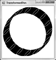
| Determines how the brush wraps the image. This property can take the values Clamp (use a single copy that overlaps the origin of the shape's bounding rectangle), Tile (tile normally), TileFlipX (tile flipping every other column of images over horizontally), TileFlipY (tile flipping every other row of images over vertically), and TileFlipXY (tile flipping every other column horizontally and every other row vertically). Figure 31-6 shows examples of these settings. |
If you look closely at Figure 31-6, you'll see that the images do not always begin in the upper-left corner of the shape being filled. The brush essentially sets its tiling origin to the form's upper-left corner and then spaces its images accordingly.
If you want to move the tiling origin, you can apply a translation transformation to the brush to move the image to the new origin. The following code creates a TextureBrush using a PictureBox's Image property to define its image and sets WrapMode to TileFlipXY. It translates the brush to the point (50, 100) and then fills a rectangle with its upper-left corner at this same point. This ensures that the first copy of the brush's image is placed exactly in the rectangle's upper-left corner. It also ensures that the first image is not flipped vertically or horizontally.
' Make a TextureBrush using the smiley face.
Using texture_brush As New TextureBrush(picSmiley.Image)
    texture_brush.WrapMode = System.Drawing.Drawing2D.WrapMode.TileFlipXY
texture_brush.TranslateTransform(50, 100)
DrawSample(e.Graphics, texture_brush, 50, 100)
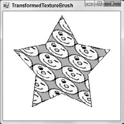
End UsingThe following code uses a transformed TextureBrush. First, it generates points to define a star-shaped polygon and creates a TextureBrush using a PictureBox Image property to define its image. Next, the program scales the brush by a factor of 2 in the X direction, making the smiley face wider than normal. It then rotates the brush by 30 degrees, fills the star-shaped polygon with the brush, and then outlines the polygon in black.
Private Sub Form1_Paint(ByVal sender As Object,
 ByVal e As System.Windows.Forms.PaintEventArgs) Handles MyBase.Paint
    ' Generate points to draw a star shape.
    Dim cx As Integer = Me.ClientSize.Width  2
    Dim cy As Integer = Me.ClientSize.Height  2
    Dim r1 As Integer = Min(cx, cy) - 10
    Dim r2 As Integer = Min(cx, cy)  2
    Dim pts(9) As Point
    For i As Integer = 0 To 9 Step 2
        pts(i).X = cx + CInt(r1 * Cos(i * PI / 5 - PI / 2))
        pts(i).Y = cy + CInt(r1 * Sin(i * PI / 5 - PI / 2))
        pts(i + 1).X = cx + CInt(r2 * Cos((i + 1) * PI / 5 - PI / 2))
        pts(i + 1).Y = cy + CInt(r2 * Sin((i + 1) * PI / 5 - PI / 2))
    Next i

    ' Make a TextureBrush using the smiley face.
    Using texture_brush As New TextureBrush(picSmiley.Image)
        texture_brush.ScaleTransform(2, 1, MatrixOrder.Append)
        texture_brush.RotateTransform(30, MatrixOrder.Append)
        e.Graphics.FillPolygon(texture_brush, pts)
    End Using

    e.Graphics.DrawPolygon(Pens.Black, pts)
End Sub
Figure 31-7 shows the result. Note that not only is the image transformed, but the tiled rows and columns are also transformed.
A hatch pattern fills an area with a simple pattern of lines, dots, or other shapes. For example, you could fill a rectangle with a series of black lines drawn at a 45 degree angle.
A TextureBrush class gives you complete control over every pixel in the filled area so you could use a simple image to build hatch patterns. However, for standard hatch patterns it's a lot easier to use the HatchBrush class.
HatchBrush is a relatively simple class. Its three most useful properties are BackgroundColor, ForegroundColor, and HatchStyle. ForegroundColor and BackgroundColor determine the colors the brush uses. HatchStyle can take one of 54 values. Example program HatchStyles, which is available for download on the book's web site, lists the HatchStyle values and shows samples.
The following code shows how a program can fill a rectangle with a HatchBrush. It makes a brush using the LargeConfetti style with a blue foreground and light blue background. It calls a Graphics object's FillRectangle method to fill a rectangle with this brush, and then calls DrawRectangle to outline the rectangle in black.
Using the_brush As New HatchBrush(HatchStyle.LargeConfetti, Color.Blue,
 Color.LightBlue)
    gr.FillRectangle(the_brush, 10, 10, 200, 200)
    gr.DrawRectangle(Pens.Black, 10, 10, 200, 200)
End Using
Figure 30-3 in Chapter 30 shows the available hatch patterns.
A LinearGradientBrush class fills areas with a linear gradient of two or more colors. The simplest of these brushes shades an area smoothly from one color to another along a specified direction. For example, a rectangle might be red at one end and shade smoothly to blue at the other.
With some extra work, you can specify exactly how the colors blend from one to the other. For example, you could make the colors blend quickly at the start and then slowly across the rest of the rectangle.
You can also specify more than two colors for the brush. You could make the colors blend from red to green to blue.
The following table describes the LinearGradientBrush class's most useful properties and methods.
PROPERTY OR METHOD | PURPOSE |
|---|---|
| A Blend object that determines how quickly the colors blend across the brush. By default, this is a simple linear blending. |
| A ColorBlend object that determines the colors (possibly more than two) that the brush blends and their positions within the blend. |
| An array of two colors that determines the starting and ending colors for a simple linear blend. |
| Multiplies the brush's current transformation by another transformation matrix. |
| Resets the brush's transformation to the identity transformation. |
| Adds a rotation transformation to the brush's current transformation. |
| Adds a scaling transformation to the brush's current transformation. |
| Makes the brush use a midpoint gradient where the color blends from the start color to the end color, and then back to the start color. You could do something similar with the Blend property, but this is easier. |
| Makes the brush's color gradient change according to a bell curve instead of linearly. |
| A transformation that the brush applies to its gradient before using it to fill areas. |
| Adds a translation transformation to the brush's current transformation. |
| Determines how the brush wraps when it doesn't completely fill the area. This property can take the values Clamp, Tile, TileFlipX, TileFlipY, and TileFlipXY. Because the brush is infinitely tall in the direction perpendicular to the line that determines its direction, not all of these values make a difference for all brushes. |
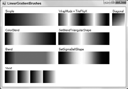
The following code draws the assortment of filled rectangles shown in Figure 31-8. As you step through the code, refer to the figure to see the result.
Private Sub Form1_Paint(ByVal sender As Object,
 ByVal e As System.Windows.Forms.PaintEventArgs) Handles MyBase.Paint
    Dim y As Integer = 10
    Dim x As Integer = 10
    Dim wid As Integer = 200
    Dim hgt As Integer = 50

    ' Make a rectangle that shades from black to white.

    e.Graphics.DrawString("Simple", Me.Font, Brushes.Black, x, y)
    y += 15
    Using black_white_brush As New LinearGradientBrush(
     New Point(x, y), New Point(x + wid, y), Color.Black, Color.White)
        e.Graphics.FillRectangle(black_white_brush, x, y, wid, hgt)
        y += hgt + 10

        ' ColorBlend.
        e.Graphics.DrawString("ColorBlend", Me.Font, Brushes.Black, x, y)
        y += 15
        Dim color_blend As New ColorBlend(3)
        color_blend.Colors = New Color() {Color.Red, Color.Green, Color.Blue}
        color_blend.Colors = New Color() _
            {Color.Black, Color.White, Color.Black}
        color_blend.Positions = New Single() {0.0, 0.2, 1.0}
        black_white_brush.InterpolationColors = color_blend
        e.Graphics.FillRectangle(black_white_brush, x, y, wid, hgt)
        y += hgt + 10

        ' Make a brush that makes 50 percent of the color change
        ' in the first 20 percent of the distance, stays there
        ' until 80 percent of the distance, and then finishes
        ' in the remaining distance.
        e.Graphics.DrawString("Blend", Me.Font, Brushes.Black, x, y)
        y += 15
        Dim the_blend As New Blend(4)
        the_blend.Factors = New Single() {0.0, 0.5, 0.5, 1.0}
        the_blend.Positions = New Single() {0.0, 0.2, 0.8, 1.0}
        black_white_brush.Blend = the_blend
        e.Graphics.FillRectangle(black_white_brush, x, y, wid, hgt)
        y += hgt + 10

        ' This brush's line is too short to cross the whole rectangle.
        e.Graphics.DrawString("Short", Me.Font, Brushes.Black, x, y)
        y += 15
        Using short_brush As New LinearGradientBrush(
         New Point(x, y), New Point(x + 50, y),
         Color.Black, Color.White)
            e.Graphics.FillRectangle(short_brush, x, y, wid, hgt)
            y += hgt + 10

            x += wid + 10
            y = 10

            ' Change the brush's WrapMode.
            e.Graphics.DrawString("WrapMode = TileFlipX", Me.Font,
                Brushes.Black, x, y)
y += 15
short_brush.WrapMode = WrapMode.TileFlipX
e.Graphics.FillRectangle(short_brush, x, y, wid, hgt)
y += hgt + 10
End Using ' short_brush
' Trangular brush.
e.Graphics.DrawString("SetBlendTriangularShape", Me.Font,
Brushes.Black, x, y)
y += 15
black_white_brush.SetBlendTriangularShape(0.5)
e.Graphics.FillRectangle(black_white_brush, x, y, wid, hgt)
y += hgt + 10
End Using ' black_white_brush
' Sigma bell shape.
e.Graphics.DrawString("SetSigmaBellShape", Me.Font, Brushes.Black, x, y)
y += 15
black_white_brush.SetSigmaBellShape(0.5, 1)
e.Graphics.FillRectangle(black_white_brush, x, y, wid, hgt)
y += hgt + 10
' A diagonal brush.
x += wid + 10
y = 10
wid = hgt
e.Graphics.DrawString("Diagonal", Me.Font, Brushes.Black, x, y)
y += 15
Dim diag_brush As New LinearGradientBrush(
New Point(x, y), New Point(x + wid, y + hgt), Color.Black, Color.White)
e.Graphics.FillRectangle(diag_brush, x, y, wid, hgt)
y += hgt + 10
End Sub
The code begins by making a relatively straightforward LinearGradientBrush shading from black to white along the line starting at (9, 10) and ending at (210, 10). It then fills a rectangle with the brush. Notice that the points defining the brush determine the brush's drawing origin. The rectangle's X coordinates cover the same range as those of the brush, so the brush's origin lines up nicely with the rectangle. If the two did not line up, the brush would finish its gradient before it reached the end of the rectangle and it would need to wrap. Usually, you will want the brush to line up with the object it is filling. You can arrange that by carefully defining the brush to fit over the object or by using a transformation to make it fit.
Next, the code creates a ColorBlend object. It passes the object's constructor the value 3 to indicate that it will use three colors. The code sets the ColorBlend object's Colors property to an array containing the three colors black, white, and black. This example uses black and white, so the result will show up well in the book, but you could use any colors here such as orange, hot pink, and blue. Next, the code sets the ColorBlend object's Positions property to an arra of Singles that define the positions within the blend where the colors should be located. In this example, the first color (black) begins 0.0 of the way through the blend, the second color (white) sits 0.2 or 20 percent of the distance through the blend, and the third color (black again) sits at the end of the blend. You can see in Figure 31-8 that the white area is to the left of the center in this rectangle.
The code then creates a Blend object, passing its constructor the parameter 4 to indicate that the program will set four blend points. It sets the object's Factors property to an array of Singles that determine the fraction of the blend that should occur at the four points. It then sets the object's Positions property to an array that sets the positions of the blend points. In this example, the point 0.0 of the distance through the blend has factor 0.0, so the blend has not begun and that point has the start color. The point 0.2 of the distance through the blend has a factor of 0.5, so the blend should be half done at that point. The point 0.8 of the distance through the blend has a factor of 0.5, so the blend should still be only half done at that point. Finally, the point at the end of the blend should have the end color. The result is a blend that changes quickly initially, remains fixed for a stretch in the middle, and then finishes quickly. (An optical illusion makes the area on the left of the flat region in the middle appear brighter than it really is, and the area on the right appears darker than it really is.)
Next, the program makes a LinearGradientBrush that is defined by points too close together to cover its whole rectangle. The brush repeats its gradient as many times as necessary to cover the rectangle.
The program then changes the previous brush's WrapMode property to TileFlipX. When the brush must repeat its gradient to fill the rectangle, it reverses the start and end colors to produce a series of gradient bands.
Next, the program calls a brush's SetBlendTriangularShape method. This makes the gradient shade from the start color to the end color and back. The SetBlendTriangularShape method's parameter gives the position in the gradient where the end color should occur. You could get a similar effect using a Blend, but this method is easier for this kind of fill.
The program then calls the brush's SetSigmaBellShape method. It uses the same position parameter 0.5 as the previous call to SetBlendTriangularShape, so it places the end color in the middle of the gradient. The effect is similar to the triangular brush, except that the colors vary according to a bell curve instead of linear relationship. These two rectangles are lined up vertically in Figure 31-8, so it is easy to see the difference.
The code defines the final brush with a line that is not horizontal, so its gradient moves diagonally across its rectangle.
A PathGradientBrush object fills areas with a color gradient that blends colors from a center point to the points along a path. For example, you might shade from white in the middle of an ellipse to blue along its edges.
The Blend, InterpolationColors, SetBlendTriangularShape, SetSigmaBellShape, and other properties and methods that deal with the characteristics of the blend work along lines running from the center point to the points on the path. For example, you can use this object's Blend property to determine how quickly colors blend across the brush. In the LinearGradientBrush class, this property determines how the colors blend from one side of the brush to the other. In a PathGradientBrush, it controls how the colors blend from the center point to the path's points.
The following table describes the PathGradientBrush object's most useful properties and methods.
PROPERTY OR METHOD | PURPOSE |
|---|---|
| A Blend object that determines how quickly the colors blend across the brush. By default, this is a simple linear blending. |
| Determines the color at the center point. |
| Determines the location of the center point. By default, this point is set to the center of the path. |
| A ColorBlend object that determines the colors (possibly more than two) that the brush blends and their positions within the blend. |
| Multiplies the brush's current transformation by another transformation matrix. |
| Resets the brush's transformation to the identity transformation. |
| Adds a rotation transformation to the brush's current transformation. |
| Adds a scaling transformation to the brush's current transformation. |
| Makes the brush use a midpoint gradient where the color blends from the start color to the end color and then back to the start color. You could do something similar with the Blend property, but this is easier. |
| Makes the brush's color gradient change according to a bell curve instead of linearly. |
| An array of Colors that correspond to the points on the path. The color gradient blends from the CenterColor to these colors around the edge of the path. If there are more points in the path than colors, the final color is repeated as needed. Note that curves such as ellipses define a large number of colors that you do not explicitly specify, so making these colors match up with points on the curve can be difficult. This property is easier to understand for polygons. |
| A transformation that the brush applies to its gradient before using it to fill areas. |
TranslateTransform | Adds a translation transformation to the brush's current transformation. |
WrapMode | Determines how the brush wraps when it doesn't completely fill the area. This property can take the values Clamp, Tile, TileFlipX, TileFlipY, and TileFlipXY. Because the brush is infinitely tall in the direction perpendicular to the line that determines its direction, not all of these values make a difference for all brushes. |
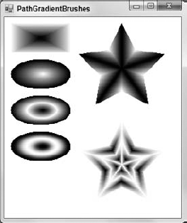
Example program PathGradientBrushes, which is available for download on the book's web site, uses PathGradientBrush objects to draw the shapes shown in Figure 31-9.
The following code fills the shapes shown in Figure 31-9. As you step through the code, refer to the figure to see the result.
Private Sub Form1_Paint(ByVal sender As Object,
 ByVal e As System.Windows.Forms.PaintEventArgs) _
Handles MyBase.Paint
    e.Graphics.SmoothingMode = SmoothingMode.AntiAlias

    Dim x As Integer = 10
    Dim y As Integer = 10
    Dim wid As Integer = 50
    Dim hgt As Integer = 100

    ' Fill a rectangle.
    Dim rect_pts() As Point = {
        New Point(x, y),
        New Point(x + wid, y),
        New Point(x + wid, y + hgt),
        New Point(x, y + hgt)
    }
    Dim path_brush As New PathGradientBrush(rect_pts)
    e.Graphics.FillPolygon(path_brush, rect_pts)
    x += wid + 10

    ' Fill an ellipse setting CenterColor and SurroundColors.
    Dim ellipse_path As New GraphicsPath
    ellipse_path.AddEllipse(x, y, wid, hgt)
    path_brush = New PathGradientBrush(ellipse_path)
    path_brush.CenterColor = Color.White
    path_brush.SurroundColors = New Color() {Color.Black}
    e.Graphics.FillEllipse(path_brush, x, y, wid, hgt)
    x += wid + 10

    ' Fill an ellipse using SetBlendTriangularShape.
    ellipse_path = New GraphicsPath
ellipse_path.AddEllipse(x, y, wid, hgt)
path_brush = New PathGradientBrush(ellipse_path)
path_brush.CenterColor = Color.White
path_brush.SurroundColors = New Color() {Color.Black}
path_brush.SetBlendTriangularShape(0.5)
e.Graphics.FillEllipse(path_brush, x, y, wid, hgt)
x += wid + 10
' Fill an ellipse using SetSigmaBellShape.
ellipse_path = New GraphicsPath
ellipse_path.AddEllipse(x, y, wid, hgt)
path_brush = New PathGradientBrush(ellipse_path)
path_brush.CenterColor = Color.White
path_brush.SurroundColors = New Color() {Color.Black}
path_brush.SetSigmaBellShape(0.5, 1)
e.Graphics.FillEllipse(path_brush, x, y, wid, hgt)
x += wid + 10
' Fill a star shape.
wid = 150
hgt = 150
Dim cx As Integer = x + wid 2
Dim cy As Integer = y + hgt 2
Dim r1 As Integer = CInt(wid * 0.5)
Dim r2 As Integer = CInt(hgt * 0.25)
Dim star_pts(9) As Point
For i As Integer = 0 To 9 Step 2
star_pts(i).X = cx + CInt(r1 * Cos(i * PI / 5 - PI / 2))
star_pts(i).Y = cy + CInt(r1 * Sin(i * PI / 5 - PI / 2))
star_pts(i + 1).X = cx + CInt(r2 * Cos((i + 1) * PI / 5 - PI / 2))
star_pts(i + 1).Y = cy + CInt(r2 * Sin((i + 1) * PI / 5 - PI / 2))
Next i
Dim star_path As New GraphicsPath
star_path.AddPolygon(star_pts)
Dim star_brush As New PathGradientBrush(star_pts)
star_brush.CenterColor = Color.Black
star_brush.SurroundColors = New Color() {
Color.Black, Color.White,
Color.Black, Color.White,
Color.Black, Color.White,
Color.Black, Color.White,
Color.Black, Color.White
}
e.Graphics.FillPolygon(star_brush, star_pts)
x += wid + 10
' Fill a star shape.
cx = x + wid 2
cy = y + hgt 2
r1 = CInt(wid * 0.5)
r2 = CInt(hgt * 0.25)
For i As Integer = 0 To 9 Step 2
star_pts(i).X = cx + CInt(r1 * Cos(i * PI / 5 - PI / 2))star_pts(i).Y = cy + CInt(r1 * Sin(i * PI / 5 - PI / 2))
star_pts(i + 1).X = cx + CInt(r2 * Cos((i + 1) * PI / 5 - PI / 2))
star_pts(i + 1).Y = cy + CInt(r2 * Sin((i + 1) * PI / 5 - PI / 2))
Next i
star_path = New GraphicsPath
star_path.AddPolygon(star_pts)
star_brush = New PathGradientBrush(star_pts)
star_brush.CenterColor = Color.White
star_brush.SurroundColors = New Color() {
Color.White, Color.Black,
Color.White, Color.Black,
Color.White, Color.Black,
Color.White, Color.Black,
Color.White, Color.Black
}
Dim star_blend As New Blend
star_blend.Positions = New Single() {0.0, 0.25, 0.5, 0.75, 1.0}
star_blend.Factors = New Single() {0.0, 1.0, 0.0, 1.0, 0.0}
star_brush.Blend = star_blend
e.Graphics.FillPolygon(star_brush, star_pts)
' Draw the outline in white to remove some
' incorrectly drawn pixels.
e.Graphics.DrawPolygon(Pens.White, star_pts)
path_brush.Dispose()
ellipse_path.Dispose()
star_brush.Dispose()
star_path.Dispose()
End Sub
The code first creates an array of Point objects initialized to form a rectangle. It passes those points to the constructor for a PathGradientBrush and then uses the brush to fill that rectangle. This is about the simplest PathGradientBrush you can build, so it's worth studying a bit before moving on to more confusing examples. Notice that the color shades smoothly from black in the center to white on the rectangle's edges (those are the default colors).
Next, the program makes a GraphicsPath object and adds an ellipse to it. It passes the GraphicsPath to the PathGradientBrush object's constructor. It then sets the brush's CenterColor and SurroundColors properties. The SurroundColors array doesn't contain enough values for every point on the elliptical path, so the last color (black) is repeated as much as necessary. The program fills the ellipse with this brush.
The code then creates a new GraphicsPath object, adds a new ellipse, and uses it to make a PathGradientBrush as before. It also sets the brush's CenterColor and SurroundColors properties as before. The program then calls the brush's SetBlendTriangularShape method to make the colors along the lines from the center point to the path's edges blend from the end color to the start color and back. The parameter 0.5 makes the start color appear halfway from the center point to the edge.
Next, the program repeats these same steps, except that it calls the brush's SetSigmaBellShape method instead of SetBlendTriangularShape. The result is similar to the previous result, except that the colors vary according to a bell curve instead of a linear relationship.
The code then generates an array of points that defines a star shape. It creates a new GraphicsPath object and calls its AddPolygon method to add the star. It passes this GraphicsPath object to the PathGradientBrush object's constructor to make the brush use the star as its path. The program then sets the brush's SurroundPoints property to an array containing the Colors it should use for each of the star's points. The code fills the star using this brush to draw a star where the tips of the star are black and the rest of the shape's points vary from white to black.
Finally, the program repeats the previous steps to define a new star-shaped brush. It creates a new Blend object and sets its Position and Factors properties to indicate how the gradient should progress from the center point to the shape's edges. The Positions values give locations along a line from the center to an edge point. The Factors values indicate how far the blend should have progressed for the corresponding point. For example, this code's second entries for those arrays are 0.25 and 1.0 to indicate that the point one quarter of the distance from the center point to an edge point should have blended completely to the end color. This example sets its Factors values so the color blends from the start color to the end color several times.
A GraphicsPath object represents a path defined by lines, curves, text, and other drawing commands. A GraphicsPath can even include other GraphicsPath objects.
You can use a Graphics object's DrawPath and FillPath methods to draw or fill a GraphicsPath. For example, the following code creates a GraphicsPath object and adds a string to it. It creates a TextureBrush from a PictureBox image and uses the FillPath method to fill the path with the TextureBrush. It finishes by calling the DrawPath method to outline the path in black.
Private Sub Form1_Paint(ByVal sender As Object,
 ByVal e As System.Windows.Forms.PaintEventArgs) Handles MyBase.Paint
    ' Make a GraphicsPath containing text.
    Dim txt As String = "Path"
    Using graphics_path As New GraphicsPath()
        graphics_path.AddString(txt,
            New FontFamily("Times New Roman"),
            FontStyle.Bold, 150,
            New Point(0, 0),
            New StringFormat)

        ' Fill the path with an image.
        Using smiley_brush As New TextureBrush(picSmiley.Image)
            e.Graphics.FillPath(smiley_brush, graphics_path)
        End Using
        e.Graphics.DrawPath(Pens.Black, graphics_path)
    End Using
End Sub

Figure 31-10 shows the result.

Figure 31.10. A program can use a Graphics object's FillPath and DrawPath methods to fill and draw a GraphicsPath object.
In addition to drawing and filling a GraphicsPath, you can also use one to define a region. The following code creates a GraphicsPath representing text much as the previous example does. It then sets the form's Regin property equal to a new Region object created from the GraphicsPath. This restricts the form to the region. Any pieces of the form that lie outside of the textual path are chopped off, so they are not drawn and mouse events in those areas fall through to whatever lies below the form.
When you use a path to define a form's region, the path is taken relative to the form's origin, which is not the same as the origin of the form's client area. The form's origin is at the upper-left corner of the form, including its borders and title bar. To allow for this difference in origins, the code uses the PointToScreen method to get the screen coordinates of the client area's origin.
The code applies a translation transformation to the Graphics object so the client area origin is mapped to the form's origin. It then sets the Graphics object's SmoothingMode, fills the path with light gray, and then outlines the path with a thick black pen. Because the 5-pixel-wide line around the path is centered on the edge of the form's region, half of it is cut off.
Private Sub Form1_Paint(ByVal sender As Object,
 ByVal e As System.Windows.Forms.PaintEventArgs) Handles MyBase.Paint
    ' Make a GraphicsPath containing text.
    Dim txt As String = "Path"
    Using graphics_path As New GraphicsPath()
        graphics_path.AddString(txt,
            New FontFamily("Times New Roman"),
            FontStyle.Bold, 150,
            New Point(0, 0),
            New StringFormat)

        ' Set the form's region to the path.
        Me.Region = New Region(graphics_path)

        ' Fill the path with white and outline it in black.
        Dim origin As Point = Me.PointToScreen(New Point(0, 0))
        e.Graphics.TranslateTransform(Me.Left - origin.X, Me.Top - origin.Y)
        e.Graphics.SmoothingMode = SmoothingMode.AntiAlias
        e.Graphics.FillPath(Brushes.LightGray, graphics_path)

        Using black_pen As New Pen(Color.Black, 5)
            e.Graphics.DrawPath(black_pen, graphics_path)
        End Using
    End Using
End Sub

The result is a form shaped to fit the text in the GraphicsPath. Note that the path used in this example cuts the form's borders and title bar off, so the user has no way to resize, move, or close this form. If you use this technique in an application, be sure to at least provide some method for the user to close the form such as a button or context menu.
One more use for GraphicsPath objects is to define clipping regions. The following code creates a GraphicsPath containing text much as the previous examples do. It then calls the Graphics object's SetClip method to make this path the form's clipping region. Next, the program draws 200 lines between randomly generated points on the form. Only the parts of the lines inside the clipping region are drawn.
Private Sub Form1_Paint(ByVal sender As Object,
 ByVal e As System.Windows.Forms.PaintEventArgs) Handles MyBase.Paint
    ' Make a GraphicsPath containing text.
    Dim txt As String = "Path"
    Using graphics_path As New GraphicsPath
        graphics_path.AddString(txt,
            New FontFamily("Times New Roman"),
            FontStyle.Bold, 150,
            New Point(0, 0),
            New StringFormat)
        e.Graphics.SetClip(graphics_path)
    End Using

    ' Fill the ClientRectangle with white.
    e.Graphics.FillRectangle(Brushes.White, Me.ClientRectangle)

    ' Draw a bunch of random lines on the form.
    Dim rnd As New Random
    Dim x1, y1, x2, y2 As Integer
    For i As Integer = 1 To 200
        x1 = rnd.Next(0, Me.ClientSize.Width - 1)
        y1 = rnd.Next(0, Me.ClientSize.Height - 1)
        x2 = rnd.Next(0, Me.ClientSize.Width - 1)
        y2 = rnd.Next(0, Me.ClientSize.Height - 1)
        e.Graphics.DrawLine(Pens.Black, x1, y1, x2, y2)
    Next i
End Sub
The GraphicsPath class provides many methods for adding lines, curves, text, and other shapes to the path. These methods include AddArc, AddBezier, AddBeziers, AddClosedCurve, AddCurve, AddEllipse, AddLine, AddLines, AddPath, AddPie, AddPolygon, AddRectangle, AddRectangles, and AddString. These are roughly analogous to the Draw and Fill methods provided by the Graphics object. For example, DrawEllipse draws an ellipse, FillEllipse fills an ellipse, and AddEllipse adds an ellipse to a path.
The following table describes the GraphicsPath object's other most useful properties and methods.
PROPERTY OR METHOD | PURPOSE |
|---|---|
| Closes all open figures by connecting their last points with their first points, and then starts a new figure. |
| Closes the current figure by connecting its last point with its first point, and then starts a new figure. For example, if you draw a series of lines and arcs, this method closes the figure. |
| Determines how the path handles overlaps when you fill it. This property can take the values Alternate and Winding. Figure 31-11 shows the difference. |
| Converts any curves in the path into a sequence of lines. For example, this lets you explicitly calculate colors for every point in the path when setting a PathGradientBrush object's SurroundColors property. |
| Returns a RectangleF structure representing the path's bounding box. |
| Returns the last PointF structure in the PathPoints array. |
| Returns True if the indicated point lies beneath the path's outline. |
| Returns True if the indicated point lies within the path's interior. |
| Returns a PathData object that encapsulates the path's graphical data. It holds arrays similar to those returned by the PathPoints and PathTypes properties. |
| Returns an array of PointF structures giving the points in the path. |
| Returns an array of Bytes representing the types of the points in the path. |
| Returns the number of points in the path. |
| Clears the path data and resets FillMode to Alternate. |
| Reverses the order of the path's data. |
| Starts a new figure so future data is added to the new figure. Later, calling CloseFigure will close this figure, but not the previous one. |
| Applies a transformation matrix to the path. |
| Applies a warping transformation to the path. The transformation is defined by mapping a parallelogram to a rectangle. |
| Enlarges the curves in the path to enclose a line drawn by a specific pen. |

Objects such as brushes contain references to memory and graphics resources. If you allocate a lot of brushes and then let them go out of scope, they become candidates for garbage collection. Later, when the system decides it needs to free some memory, it walks through all of the objects that you have previously allocated and determines which ones are not reachable by your code. It frees those objects and makes their memory available for future use.
Unfortunately, if those objects contain references to other objects, the garbage collector may think those second-hand objects are still referenced by the original object, so it will not collect them until it runs a second time.
For example, suppose that your program allocates a brush, uses it, and lets it fall out of scope. When the garbage collector runs, it sees that the brush refers to some resources, so it doesn't reclaim them. It sees that your program is no longer using the brush, however, so it frees that memory. The next time the garbage collector runs, the brush is gone, so nothing refers to the brush's secondary resources and the garbage collector can free those, too.
Although the garbage collector eventually frees all of the memory, it takes longer than necessary. It ties up memory longer and that may force more frequent garbage collection.
You can speed up the process greatly by explicitly calling the brush object's Dispose method. Dispose makes the brush free its internal resources and prepare for garbage collection. Now, when the garbage collector runs, it frees both the brush and its secondary resources in a single pass.
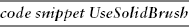
The following code shows how to use the Dispose method. When the form loads, this code makes a new Bitmap object to fit the form. It attaches a Graphics object to the Bitmap, makes a HatchBrush and Pen, and uses them to draw a filled ellipse on the Bitmap. The program then sets the form's BackgroundImage property to the Bitmap. Finally, the code calls the Dispose method for the HatchBrush, Pen, and Graphics objects.
Private Sub Form1_Load() Handles MyBase.Load
    ' Make a new bitmap to fit the form.
    Dim bm As New Bitmap(Me.ClientRectangle.Width, Me.ClientRectangle.Height)
    Dim gr As Graphics = Graphics.FromImage(bm)
    gr.Clear(Me.BackColor)

    ' Fill an ellipse.
    Dim hatch_brush As New HatchBrush(HatchStyle.LargeConfetti,
        Color.Blue, Color.Yellow)
    Dim rect As New Rectangle(10, 10,
        Me.ClientRectangle.Width - 20,
        Me.ClientRectangle.Height - 20)
    gr.FillEllipse(hatch_brush, rect)

    ' Outline the ellipse.
    Dim thick_pen As New Pen(Color.Black, 5)
    gr.DrawEllipse(thick_pen, rect)

    ' Set the result as the form's BackgroundImage.
    Me.BackgroundImage = bm

    ' Free resources.
    hatch_brush.Dispose()
    thick_pen.Dispose()
    gr.Dispose()
End Sub
Whenever you can call an object's Dispose method, you should do so. This lets the garbage collector reclaim memory more efficiently.
You cannot always call Dispose, however. If you call Dispose on an object that is still needed by some other object, the program will crash. For example, the preceding code uses a Bitmap object. It's not obvious from the code, but the form's BackgroundImage property continues to reference that object after this subroutine exits. If the program calls the Bitmap object's Dispose method, the form will later be unable to redraw itself and will either crash or display a panicked error message depending on your operating system and .NET Framework version.
Instead of calling Dispose explicitly, you can use the Using statement. Declare the variable that you must dispose of with a Using statement. When you have finished with the variable, end the Using block with an End Using statement. When Visual Basic reaches the End Using statement, it automatically calls the variable's Dispose method.
The following code is similar to the previous version, except that it uses Using statements instead of calling the Dispose method explicitly:
Private Sub Form1_Load() Handles MyBase.Load
    ' Make a new bitmap to fit the form.
    Dim bm As New Bitmap(Me.ClientRectangle.Width, Me.ClientRectangle.Height)
    Using gr As Graphics = Graphics.FromImage(bm)
        gr.Clear(Me.BackColor)
        Dim rect As New Rectangle(10, 10,3
Me.ClientRectangle.Width - 20,
Me.ClientRectangle.Height - 20)
' Fill an ellipse.
Using hatch_brush As New HatchBrush(HatchStyle.LargeConfetti,
Color.Blue, Color.Yellow)
gr.FillEllipse(hatch_brush, rect)
End Using
' Outline the ellipse.
Using thick_pen As New Pen(Color.Black, 5)
gr.DrawEllipse(thick_pen, rect)
End Using
' Set the result as the form's BackgroundImage.
Me.BackgroundImage = bm
End Using ' gr
End Sub
The Using statement increases the nesting depth of the code. In this example, the FillEllipse and DrawEllipse calls are contained in two nested Using blocks, so they are indented twice. That makes the code a little harder to read, but it makes it less likely that you will forget to call the objects' Dispose methods. In most cases, the increase is a small price to pay, particularly for graphics programs that may use hundreds or thousands of pens and brushes very quickly.
Visual Basic .NET provides a huge variety of objects for drawing graphics. The three most important drawing classes are Graphics, Pen, and Brush.
The Graphics object represents the canvas on which you will draw. It provides methods that let you draw and fill all sorts of shapes including lines, rectangles, ellipses, polygons, text, and curves. It also provides methods for transforming those commands to translate, scale, and rotate the results.
The Pen object determines the appearance of lines. It sets the lines' color, thickness, dash style, fill pattern, and caps.
Various kinds of brush objects determine the appearance of filled areas. They can fill areas with solid colors, tiled images, hatch patterns, linear color gradients, and color gradients that follow a path.
These classes and the others described in this chapter give you powerful tools for drawing graphics of practically unlimited complexity and sophistication.
This chapter discusses the brushes, pens, and paths that you use to draw lines, curves, and other shapes. Chapter 32, "Text," explains how to draw text. Although you can display simple text in a Label, TextBox, or other control, when you draw text using GDI+ routines you have greater control over exactly how the text appears.