
Introducing parametric drawing
Understanding constraints
Applying geometric and dimensional constraints
Editing parametric drawings
Note
I'm planting the New in 2010 icon at the very beginning of this chapter, and you're not going to see it again because everything I discuss in this chapter is brand new in this release.
AutoCAD 2010 includes a set of parametric drawing tools and, offhand, I can't think of a more significant new feature in recent years. (Don't worry, I'm going to offer a definition of parametric in just a few more paragraphs.) In fact, if you work primarily in 2D, and especially if you're in the manufacturing business, the addition of parametrics to AutoCAD 2010 is probably the most significant new feature ever.
If you know what I'm talking about, you're probably pretty interested in finding out more about what you can do with parametrics. If you know what I'm talking about and you're using an older AutoCAD release, maybe I've already convinced you to think about an upgrade. If, on the other hand, you think parametrics are the folks who show up when you dial 911, the following paragraphs should straighten you out.
Parametric (rule-based) drawing is by far the best way of enforcing design intent in 2D drafting. Design intent in AutoCAD 2010 (or any other engineering software) means that when drawings are edited — this part made wider, that hole made larger — all the attached or related objects behave in a predictable way that honors the designer's intent when she created the drawing in the first place.
Before AutoCAD 2010, there was simply no way of maintaining the design concepts that went into a drawing. You could use AutoCAD's drawing and editing commands to draw accurate, precise plans, sections, and details, but as far as AutoCAD was concerned, they were just a bunch of lines and circles.
Take, for example, that base plate drawing example in Chapter 3. Maybe the engineer has had a second look and determined that those 1 1/2 inch (38 mm for the metric crowd) bolts aren't quite up to the job — they need to be changed to 1 3/4 inch (44 mm). To revise the drawing using AutoCAD in the traditional way, you draw a new, larger circle for the bolt and erase the old one. Now the nut is too small, and so is the hole in the plate (maybe you can't see it, but you know and I know it's there). There's a whole lot of editing required to fix this drawing.
In AutoCAD 2010, you can add some intelligence to those lines and circles by applying constraints to them. For example, you could apply a dimensional constraint to the bolt circle and the hole circle such that the hole circle is always 1/16″ (2 mm) bigger than the bolt circle. And while you're at it, you'd probably want to apply a concentric geometric constraint between the circles so that whenever the bolt circle moved, the hole circle moved with it.
Now that is intelligent design!
As you might have guessed, the adjective parametric is derived from the noun parameter (and so endeth today's English lesson). If you look up parameter in most dictionaries, you'll get an explanation in terms of pure math — and that's waaaay deeper than you need to go. For the purposes of making drawings in AutoCAD, think of a parameter as a rule — and therefore think of parametric drawing as rule-based drawing.
AutoCAD's parametric rules (officially they're called constraints) fall into two categories:
Dimensional constraints: Based on dimensioned distances on or between objects or points on objects. For example, you could apply a dimensional constraint to two lines that represent a wall thickness so that regardless of where you moved them or how you rotated them, they would always be 6″ apart.
Geometric constraints: Based on object types and relationships between objects; different object types have different potential constraints. For example, you can apply a concentric constraint to an arc and a circle so that when you move one, it maintains its position in relation to the other.
Note
Both AutoCAD and AutoCAD LT support constraints, but as is usually the case, the feature is limited in LT. If you use the full version, you can create and modify geometric and dimensional constraints, as I describe in the steps in this chapter. If you're using LT, you can't create either type of restraint, but you can work with existing constraints in drawings that were created in the full version. Figure 19-1 shows the difference between the AutoCAD and AutoCAD LT Parametric tabs.
Tip
If you're using AutoCAD LT, or if you just want to check out some ready-made parametric possibilities, you can download the sample drawing datasets from either www.autodesk.com/autocad-samples or www.autodesk.com/autocadlt-samples. The parametric samples are architectural_example-imperial.dwg, civil_example-imperial.dwg, and mechanical_example-imperial.dwg.

You can apply dimensional or geometric constraints to new geometry as you create it, or you can assign constraints to existing geometry in old drawings. You can even convert existing associative dimensions to dynamic dimensional constraints. The following sections describe the available constraints in each of the two categories. I start with dimensional constraints, as they're conceptually a little easier to understand, and they nearly all have analogues to regular dimension commands (which I cover in Chapter 14).
The normal practice in AutoCAD is to create some geometry — of course, using all the precision techniques I discuss in Chapter 7 — and then apply dimensions as I describe in Chapter 14. Assuming that you're using fully associative dimensions, you can then edit the geometry and watch the dimensions update automatically. The length of the line or the radius of the circle are in control, and those dimensions are called driven dimensions because they change when the object geometry changes.
Dimensional constraints, unlike regular AutoCAD dimensions, are driving dimensions, which means that when you change the value of a dynamic dimension on a line, the line changes to match — in other words, the length of the line is being driven by the dimension, not the other way around.
There are only eight dimensional constraint options, but they cover all the bases. Table 19-1 lists them and describes their purposes.
Table 19-1. Dimensional Constraints
Note
The objects you add to your drawing from the Dimensional panel are not the same as the dimension objects you add from the Annotate tab. Dimensional constraints are driving dimensions — that means when you change the value of one of these dimensions, the geometry changes.
Tip
A lot is happening behind the scenes as you apply parametric constraints. You can get a great sense of how these constraints work at keeping your drawing objects in order by trying the STRETCH command on objects after you apply a constraint to them.
The following steps are a simple example of dimensional constraints:
Start a new drawing and make the Ribbon's Parametric tab current.
Turn on some appropriate precision drawing aids on the status bar, such as Snap, Ortho, and Osnap.
Draw some reasonable precise geometry using some of those precision techniques I describe in earlier chapters.
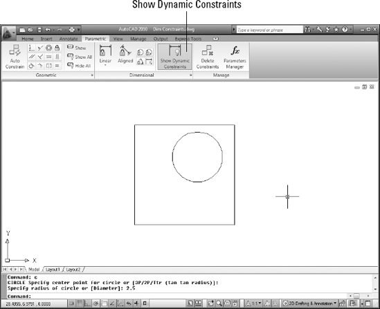
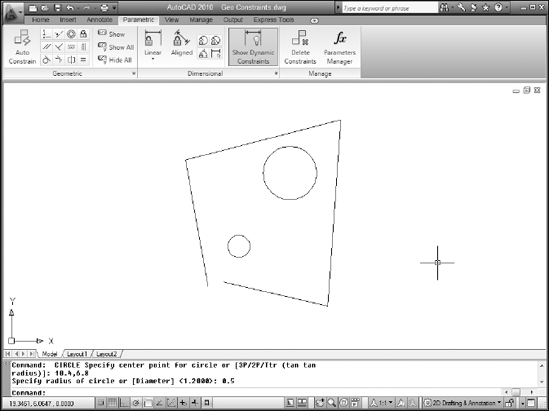
In the following example, I've used the RECTANG and CIRCLE commands to draw the geometry you see in Figure 19-2. The rectangle is 10 units square, and the 2.5-unit-radius circle is deliberately drawn away from the middle of the square.
Tip
Make sure that Show Dynamic Constraints in the Ribbon's Dimensional panel is turned on (see Figure 19-2; the button is blue when it's enabled) — otherwise, your dynamic dimensional constraints will disappear as soon as you place them.

A linear dimension icon appears beside the pickbox.
Like the DIMLINEAR command, the Linear dimensional constraint tool is inferential — which way you drag the crosshairs controls whether you get a horizontal or vertical dimension. Also, like DIMLINEAR, you can press Enter at the command prompt and select an object to dimension.
Press Enter at the command prompt to confirm you want to select an object and then select the bottom horizontal line segment.
Tip
If you see red markers at the midpoint and ends of the bottom line, you didn't press Enter; you're in point selection mode, not object selection.
AutoCAD generates a preview of a dimensional constraint and prompts you for a location.
Click to locate the dimension position.
AutoCAD draws a dimensional constraint with a highlighted text field displaying the dimension name (d1 in this example) and the value returned by AutoCAD (see Figure 19-3). You could type a new value in the edit box, but for now, just press Enter to confirm the value and the dimension location.
Repeat Steps 3–5 and add a dimensional constraint to the right vertical edge of the rectangle.
AutoCAD draws a second dimensional constraint, this one named d2.

Tip
As you mouse over the Linear button, you can see that unlike its Aligned neighbor, it's in two parts. You can force a linear dimensional constraint to be either horizontal or vertical (rather than dependent on the direction in which you drag your crosshairs) by clicking the bottom part of the Linear button and making your choice from the flyout.
If this were a traditional mechanical drawing that followed the rules of drafting, those two dimensions would be enough — whoever is reading your drawing understands that if sides are parallel and perpendicular, a dimension on one side applies to the opposite side as well. But in this chapter, I'm talking about intelligent drawings that respect design intent, not dumb collections of lines and circles, even if they do follow the rules!
If you try stretching the rectangle in various ways, only the bottom and left sides are constrained to 10 units in length. You could add two more linear dimensional constraints to the unconstrained sides, but you'd have to remember to edit both dimensions. Rather than constraining both sides to be 10 units long, the way to maintain design intent is to make both sides equal in length.
Tip
You can make the two sides equal using either dimensional or geometric constraints. It's sometimes a good idea to apply some geometric constraints to your drawing so objects are at least a little locked down. In fact, in a real-world workflow, you'd be using both geometric and dimensional constraints as you produce your design.
I cover geometric constraints in a little more detail in the "Understanding Geometric Constraints" section, later in the chapter, but for now, I'm going to apply three geometric constraints so the drawing behaves more predictably.

Icons appear near the drawing geometry, showing that those three geometric constraints are active (see Figure 19-6 a few pages ahead).
I explain those icons, and geometric constraints in general, in the next section, but I'm going back to dimensional constraints to finish this drawing.
On the Dimensional panel of the Parametric tab, click Linear and add a dimensional constraint to the top horizontal line.
Click to locate the dimension, type
d1, and press Enter when AutoCAD prompts for the dimension text.Instead of having numeric values like the first two linear constraints, this new dimensional constraint displays
d3=d1.Repeat Steps 3 and 4, this time adding a constraint to the vertical line at the left and entering
d2as the dimension text.All four dynamic dimensional constraints display their name plus a value or expression.
Note
Dimensional constraints have names as well as values. They can also include expressions or formulas. You can set the default appearance of dynamic dimensional constraints by clicking the dialog-box launcher (the little arrow at the right end of the Dimensional panel label) to open the Constraint Settings dialog box with the Dimensional tab active (see Figure 19-4). The options are
Name: The first linear dimension is named d1, the second d2, and so forth. You use the dimension names in expressions.
Value: The numeric value that you enter into the dimensional constraint or that AutoCAD enters if you don't override it.
Name and Expression: The dimension name shown as equal to an expression. The expression can be a value, as in this example, or it can be a formula.

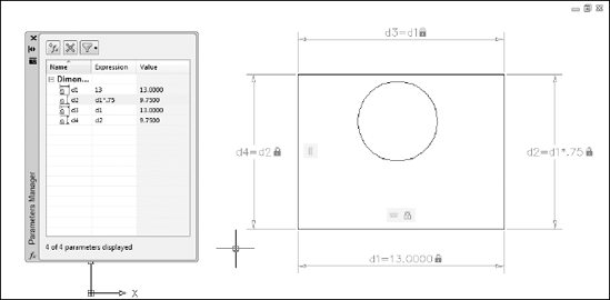
Both AutoCAD and AutoCAD LT include the Parameters Manager palette, accessible on the Manage panels of their Ribbon's Parametric tab. You can use Parameters Manager to give all those dimensional constraints more sensible names than d1 and d2, but even more usefully, you can enter expressions instead of plain numeric values, as I explain in the following steps.

The Parameters Manager palette appears, showing a list of dimensional constraints currently applied in the drawing (see Figure 19-5).
In Figure 19-5, the Expression column shows the numeric values I specified for d1 and d2 and the expressions I entered for d3 and d4. The read-only Value column shows the calculated value. You can't change a value in the Value column; you can only edit the cells in the Expression column.
In the d1 row, click in the Expression field to highlight the current value (10 in this example) and type a new value. For example, type
13and press Enter.The rectangle resizes itself in the drawing editor, and because the d3 constraint on the top side was made equal to the d1 constraint on the bottom side, both sides change equally.
Next, use an equation as an expression.
In the d2 row, click in the Expression field to highlight the current value and then type an expression. For example, type
d1*0.75and press Enter.The read-only Value column as well as the drawing geometry show that the d1 distance of 10 has been multiplied by 0.75 and is now 9.75 units long (see Figure 19-6).
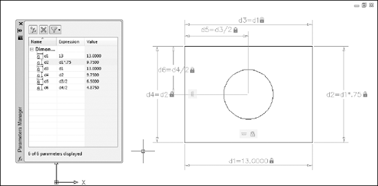
Finally, constrain the circle so its center is always at dead center of the rectangle, no matter how the rectangle's size changes.
Apply a horizontal dimensional constraint from the upper-left corner of the rectangle to the center of the circle. Locate the dimension and then type
d3/2and press Enter.The rectangle is now dimensionally constrained on all four sides, so it doesn't really matter which corner you start from. And you don't have to type the whole expression
d5=d3/2. AutoCAD knows what you mean!Repeat Step 4, this time adding a vertical constraint from one of the corners to the center of the circle. Locate the dimension and then type
d4/2.Figure 19-7 shows the object geometry with all constraints added in this section. Who knew that drafting could be such fun?

After all that hard work adding dimensional constraints to your drawings, it would be a downright shame to have to go back and apply regular dimensions, wouldn't it? Well — you don't have to — you can make dimensional constraints look and behave like regular dimensions. You can go the other way too and make your regular dimensions act like dimensional constraints.
Dimensional constraints are available in two flavors:
Dynamic constraints: The default form. Dynamic constraints appear gray with a padlock icon next to them in the drawing area. You can make them appear and disappear by clicking Show Dynamic Constraints in the Dimensional panel. They don't plot, and they resize as you zoom in and out of the drawing so they're always legible.
Annotational constraints: This form is controlled as an object property, so you have to set it in the Properties palette. Annotational constraints do plot, don't resize as you zoom in and out, and don't disappear as you toggle the Show Dynamic Constraints button on and off. Annotational constraints conform to dimension style settings.
Note
The dimension name format of annotational constraints can be set to Name, Value, or Name and Expression, just like dynamic constraints (refer to Figure 19-4 for another look at the Constraint Settings dialog box). If you're going to plot your drawing with annotational constraints, remember to reset the format so it doesn't show the dimension name or the expression.
Here's how to turn dynamic dimensional constraints into annotative constraints:
Open a drawing that contains some geometry with dimensional constraints.
You can also start a new drawing, draw some simple geometry, and add a dimensional constraint to two.
Select a dynamic constraint, right-click, and choose Properties.
The Properties palette opens with the object properties of the selected dimensional constraint listed in table form.
Click in the Constraint Form field and in the drop-down list, change Dynamic to Annotational (see Figure 19-8).
The dynamic constraint becomes annotational and takes on the appearance of the current dimension style. If you change the dimension style in the Properties palette, the annotational constraint updates to the new dimension style format.
You can go the other way too, from regular dimension objects to dimensional constraints.
Add a linear, radius, diameter, aligned, or angular dimension to your drawing geometry.
Nearly every type of dimension object has a parametric analog; the exceptions are arc length, jogged radius, jogged linear, and ordinate dimensions.

The dimensional constraint text box displays as soon as you click an associative dimension, and the dimension becomes a dynamic constraint as soon as you press Enter.
Warning
The only clue that a dimension is an annotational constraint rather than a regular old associative dimension is the padlock icon that appears next to the dimension value. You can turn off the display of the padlock in the Constraint Settings dialog box, but I recommend you leave it on. It doesn't plot anyway, and you might decide to delete the dimension without realizing it's controlling your object geometry.

Adding geometric constraints to object geometry may take a little getting used to because it's unlike anything AutoCAD has offered before.
In a few cases, AutoCAD's geometric constraints have equivalent object snaps. There are tangent, parallel, and perpendicular object snaps and tangent, parallel, and perpendicular geometric constraints. The difference between these relations as object snaps and geometric constraints is that constraints are persistent.
For example, you can draw a line at any angle, start another line, turn on parallel object snap, and create a second line that's parallel to the first. But then you can easily rotate either line so they're no longer parallel. If, however, you apply a parallel constraint to the second line, it will rotate with the first line, always maintaining that parallel relation until you delete the constraint.
There are twelve geometric constraints you can apply to your drawing objects, and the easiest way to apply them is by clicking buttons on the Geometric panel of the Ribbon's Parametric tab. Table 19-2 presents a list of the geometric constraints and explains their function.
Table 19-2. Geometric Constraints
Button Icon | Constraint Name | Description |
|---|---|---|
Coincident | Forces two or more points, such as endpoints or midpoints, to coincide; can also constrain a point to lie anywhere on an object | |
Collinear | Forces two or more lines to lie along an infinitely long projection of the first line selected | |
Concentric | Forces the centers of two or more arcs, circles, ellipses, or arc segments of polylines to coincide | |
Fix | Locks the location of an object or a point on an object to a specific location in the drawing | |
Parallel | Forces two lines to be parallel; the second line selected becomes parallel to the first line | |
Perpendicular | Forces two lines to be perpendicular to one another | |
Horizontal | Forces a line or two points to be horizontal relative to the current coordinate system | |
Vertical | Forces a line or two points to be vertical relative to the current coordinate system | |
Tangent | Forces an object to be tangent to a selected arc or circle | |
Smooth | Joins a selected spline object with another spline, line, arc, or polyline while maintaining curvature (also known as G2) continuity | |
Symmetric | Forces two objects, or two points on objects to be symmetrical about an imaginary line | |
Equal | Forces two lines or linear polyline segments to be the same length; forces two arcs or circles to have the same radius |
If you're using the full version of AutoCAD (not AutoCAD LT), you can geometrically constrain drawing objects by clicking buttons on the Geometric panel of the Parametric tab. In the following steps, I show you how to get started with geometric constraints.
Start a new drawing. Make the Ribbon's Parametric tab current and turn off Snap, Ortho, Polar, Osnap, and Otrack at the status bar.
For real drafting, you probably want to use these precision aids, but for this example, you get a better sense of parametrics with a really imprecise drawing.
Draw some linework using the PLINE command and add a couple of circles.
Draw something similar to Figure 19-9 if you want to follow closely.
Every drawing will be tackled differently. It's a good idea to think ahead and figure out the most efficient way to apply the constraints you need so that your design intent is maintained. In this example, I want to end up with two concentric circles in the middle of a square.
Tip
As I mention earlier, you'll find it a lot easier to apply constraints if at least one point on the geometry is fixed in space. In many cases, one of the first constraints you should think about applying is Fix, the one that constrains a point to one location in the drawing area.
In this example, I'll lock an endpoint of the polyline into position.

A blue padlock icon is displayed beside the pickbox, and the red pick point marker appears when you're over a point you can constrain (see Figure 19-10). In this example, I click one of the endpoints on the polyline. A padlock icon appears in the constraint bar indicating the line segment is fixed in place.
With at least one point on the geometry fixed in place, I start constraining the geometry by closing the gap in the linework.

You use a coincident constraint to make two points coincide. A blue coincident icon appears near the pickbox and, as you move your crosshairs over an object, a marker appears over relevant points — in the case of lines or polyline segments, at the endpoints and midpoint.
Tip
Use appropriate drawing commands based on your design intent. I use a polyline in this example because the ends of the segments are already coincident-constrained by being part of a single polyline object. If I draw this shape with lines, I have to apply individual coincident constraints to each corner.
Click an endpoint on the first polyline segment you want to connect and then click an endpoint on the second segment.
The endpoint of the second polyline segment jumps to the endpoint of the first line, and a small blue square — the marker for coincident constraints — appears at the intersection. (If you don't see the little blue square, click Show All in the Geometric panel.)
Next, I apply some orthographic parameters so my linework starts to look a little more like a rectangle.

The segment realigns itself horizontally from the endpoint nearest to where you picked the line, and a horizontal constraint marker — officially called a constraint bar — appears near the object.

The segment realigns itself at 90 degrees to the horizontal segment, and a constraint bar showing a vertical constraint appears. With one horizontally and one vertically constrained line segment, you're halfway to a geometrically precise rectangle!
Because rectangles have parallel and perpendicular sides, next I apply those constraints to my linework.

Because there's already a vertical constraint applied to one segment, it doesn't matter which line you pick first. If neither line had an existing constraint, the second line you picked would become parallel to the first line.
Note
Always keep your design intent in mind as you think about which constraints to apply and when to apply them. As a general rule, it's good to start with the most important and drill down to the least important. And, as I remind you above, applying a fix constraint early in the game can prevent your geometry rearranging itself in ways you don't expect.
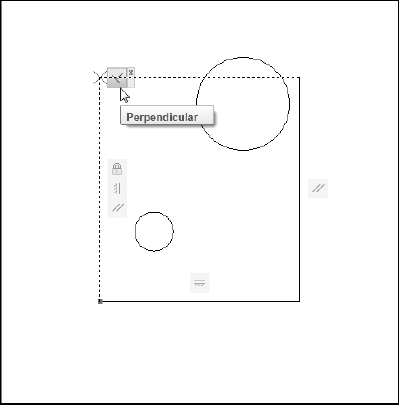
To make the final side of the almost-rectangle orthogonal with the other three, I could use another parallel constraint and click the bottom line. However, I don't want to wear out my Parallel button, so I'll use Perpendicular on the final segment.

Again, because three of the four sides are already constrained to horizontal and vertical, it doesn't matter which segment you pick first.
Tip
To delete a constraint, move the mouse pointer over the constraint marker to display the constraints bar (see Figure 19-11), right-click and choose Delete.
From four nonorthogonal, not even closed line segments, applying a handful of constraints yields a perfect rectangle — but I really want a square! Here's where the equal constraint comes in.

A perfect square! Now I want to constrain those circles.
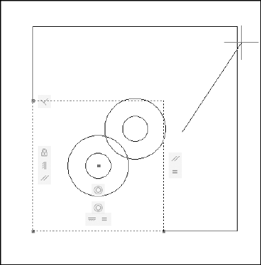
My design intent in this example is to have the circles be concentric and to locate their centers in the exact center of the rectangle. First the easy part: Making the circles concentric.

The two circles are concentrically constrained (try saying that ten times in a hurry!), and a new constraint bar appears in their vicinity. Try moving one circle by clicking it and watch the other tag along.
As I suggested, concentric was the easy constraint. I'd love to be able to use the Mid Between 2 Points object snap and just click two diagonally opposite corners to locate the circles dead center in the rectangle.
However, you can constrain only objects or points on objects, so I'm going to have to add some construction geometry in order to maintain my design intent.
Draw a line between diagonally opposite corners using Endpoint object snaps and then apply coincident constraints between the endpoints of this line and the corners of the rectangle (see Figure 9-12).
Click Coincident in the Geometric panel. Click either circle so the parametric marker appears in the center, move the pickbox over the construction line, and click when the parametric marker is over the midpoint of the line.
You're done (whew!). You can test your design intent by using the STRETCH command on the corner of the rectangle that's diagonally opposite from the one with the little blue square. As you drag the corner, you should see the two circles moving too, always maintaining their position in the middle of the rectangle (see Figure 19-13).


The Auto Constrain button on the Parametric tab's Geometric panel can apply constraints to a selection of objects with a single click — but before you execute that single click, take a look at the many Auto Constrain settings.
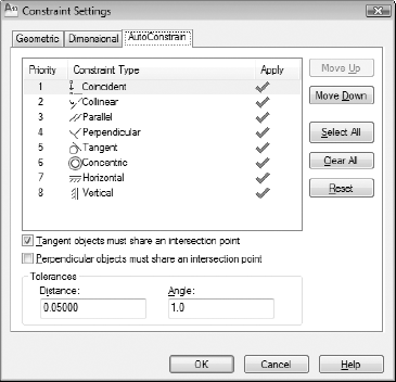
Click the dialog box launcher (the arrow at the right end of the Geometric panel label) to open the Constraint Settings dialog box with the AutoConstrain tab active (see Figure 19-14). Choose which constraints you want to apply automatically, and what order you want them in the list so the ones that should take precedence have a higher priority. Auto Constrain works only with geometric constraints, not with dimensional constraints.
The three buttons at the right side of AutoCAD's Geometric panel — and the only buttons on AutoCAD LT's Geometric panel — are for controlling the visibility of geometric constraint markers. Show All shows them all, and Hide All (surprise!) hides them all. Use the Show button to display the constraints on selected objects. This last button is a little clunky. It would be nice to be able to hover over an object and have the constraints show, but you actually have to click an object and then press Enter to see any results.
Tip
Although in this chapter, I present the two varieties of parametric constraints separately, you'll get the most mileage from this feature when you incorporate both geometric and dimensional constraints with all those other precision techniques I tell you about in Chapter 7. In fact, if you start a drawing using Snap, Ortho, Osnap, and other precision techniques before you start adding dimensional and parametric constraints, you'll be well on the way to creating a library of intelligent drawings that maintain your design intent.