


z/OS storage concepts
This chapter describes the following basic IBM z/OS storage concepts:
•Virtual storage and address spaces
•How processor storage is managed by z/OS
•How virtual storage in managed by z/OS
•Address space map for 31-bit and 64-bit
•System address spaces
•Dynamic address translation
•Residence Mode and Addressing Mode
•Subsystem definitions
•Multiprogramming and multitask
•Module object and load module
•Memory hierarchies
For more detailed information about virtual storage concepts, see ABCs of z/OS System ABCs of z/OS System Programming Volume 10, SG24-6990.
4.1 Processor storage overview

Figure 4-1 Overview of processor storage
Processor storage overview
Logically, a system consists of main storage and one or more processors. The system administers the use of processor storage and directs the movement of virtual storage pages between auxiliary storage slots and real frames in blocks of 4096 bytes. It makes all addressable virtual storage in each address space appear as main storage. Only the virtual pages necessary for program execution are kept in main storage.
The remainders exist on auxiliary storage. The system employs the auxiliary storage manager to perform the actual paging input/output (I/O) necessary to transfer pages in and out of main storage. The system also provides direct access storage device (DASD) allocation and management for paging space on auxiliary storage.
The system assigns real frames upon request from pools of available frames, thereby associating virtual addresses with main storage addresses. Frames are repossessed when freed by a user, when a user is swapped-out, or when needed to replenish the available pool. Although a virtual page occupies a real frame, the page is considered pageable unless it is fixed by the FIX option of the PGSER macro, a PGFIX macro, a PGFIXA macro, or obtained from a fixed subpool.
The system also allocates virtual equals real (V=R) regions upon request by those programs that cannot tolerate dynamic relocation. Such a region is allocated contiguously from a predefined area of main storage, and it is nonpageable.
|
Information: The terms processor storage, main storage, real storage, and memory always refer to physical memory, which is the one that resides in the processor cage.
|
The technology of main storage has the following characteristics:
•The processor is directly accessible (for programs and data).
•It is volatile, fast, and expensive, when compared with magnetic storage (DASD or tape).
|
Information: Storage is viewed as a long horizontal string of bits. For most operations, accesses to storage proceed in a left-to-right sequence. The string of bits is subdivided into units of eight bits. An eight-bit unit is called a byte, which is the basic building block of all information formats.
|
IBM /Architecture
In IBM z/Architecture, there is no expanded storage, because the 31-bit real address limitation is relieved to a 64-bit real address (up to 16 exabytes (EB) of real addresses). However, the largest mainframe (the IBM zEnterprise 196, or z196) has a total memory capacity of up to 3 terabytes (TB).
The system initialization process begins when the system operator selects the LOAD function at the system console. This causes an initial program load (IPL), which is equivalent to a boot in other platforms. z/OS locates all of the usable main storage that is online and available in the logical partition (LPAR) that has undergone IPL, creating a virtual storage environment for the building of various system areas. z/OS uses main storage to map the virtual storage, which implies allocating and using auxiliary storage.
Main storage
Main storage (sometimes referred to as central storage), provides the system with a volatile processor that is directly addressable, with fast access for the electronic storage of data.
Because of the volatile property of main storage, modern mainframes have an integrated battery feature (IBF) that keeps main storage running so operators can perform normal shutdown procedures in power failure situations.
Both data and programs must be loaded into main storage (from magnetic devices, such as disks and tapes) before they can be processed by the processors. The maximum main storage size per LPAR is restricted by hardware and the z/OS and system architecture.
Auxiliary storage
Auxiliary storage consists of z/OS paging data sets (files) located in DASD. Note that DASD in mainframe terminology is referred to as a hard disk drive on other platforms. DASD is a non-volatile magnetic memory made of iron oxide. Paging data sets are used to implement virtual storage, which contain the paged-out portions of all virtual storage address spaces.
In addition, output to virtual I/O (VIO) devices can also be stored in the paging data sets. The concept of address spaces is described in 4.2, “Virtual storage concepts” on page 250. The concept of VIO is described in 4.10, “Auxiliary storage manager” on page 265.
Processing unit
Figure 4-1 on page 248 depicts a processing unit (PU). The PU is the hardware in charge of executing instructions located in main storage. The PU contains the sequencing and processing facilities for instruction execution, interruption action, timing functions, IPLs, and other machine-related functions. PUs and main storage are packed in units known as books in the CEC cage in a z9 machine.
4.2 Virtual storage concepts

Figure 4-2 Virtual storage, auxiliary storage
Virtual storage concepts
Virtual storage is an illusion created by z/Architecture together with z/OS, such that the program seems to have more main storage that it really has. Each user or program gets an address space, and each address space contains the same range of storage addresses. Only those portions of the address space that are needed at any point in time are actually loaded into main storage. z/OS keeps the inactive pieces of address spaces in auxiliary storage.
z/OS manages address spaces in units of various sizes:
•Page address spaces are divided into 4 kilobyte (KB) units of virtual storage called pages.
•Segment address spaces are divided into 1 megabyte (MB) units called segments. A segment is a block of sequential virtual addresses spanning megabytes, beginning at a 1 MB boundary. A 2-gigabyte (GB) address space, for example, consists of 2048 segments.
•A virtual address, accordingly, is divided into four principal fields:
– Bits 0-32 are called the region index (RX).
– Bits 33-43 are called the segment index (SX).
– Bits 44-51 are called the page index (PX).
– Bits 52-63 are called the byte index (BX).
•An address (called virtual) as referred to by a program is an identifier of a required piece of information in main storage. This enables the size of an address space (all virtual addresses available to a program) to exceed the main storage size.
•All main storage references are made in terms of virtual storage address.
•A hardware mechanism called dynamic address translation (DAT) is employed to perform a mapping between the virtual storage address and its physical location in main storage.
•When a requested address is not in main storage (that is, there are more virtual addresses than bytes in main storage), an interruption is signaled and the required data is brought into memory.
Virtual storage terminology
In z/OS, virtual storage is implemented (transparently to the program) using the following concepts:
Segment Program address space is divided into segments of 1 MB addresses in size.
Page A segment is divided into pages, which are blocks of 4 KB addresses in size.
Frame Main storage is divided into frames, which are blocks of 4 KB in size.
Slots Auxiliary storage page data sets are formatted in slots, which are blocks of 4 KB in size.
DAT DAT is implemented by hardware and by software throughout page tables and segment tables.
A z/OS program accesses addresses located in virtual storage. Only pages of the program currently active need to be in a main storage frame at processing time. The inactive pages are held in auxiliary storage.
Page data sets
Page data sets contain the paged-out portions of all virtual storage address spaces. In addition, output to VIO devices can be stored in the paging data sets. Before the first IPL, an installation must allocate sufficient space on paging data sets to back up the following virtual storage areas:
•Primary storage for the pageable portions of the common area
A common area is a data-only section that can be shared by multiple address spaces. z/OS is structured around address spaces, which are ranges of addresses in virtual storage. Each user of z/OS gets an address space containing the same range of storage addresses. The use of address spaces in z/OS supports isolation of private areas in different address spaces for system security, yet also allows for inter-address space sharing of programs and data through a common area accessible to every address space.
•Secondary storage for duplicate copies of the pageable common area
The system uses the system's page data sets to keep track of auxiliary storage slots. Specifically:
– Slots for virtual storage pages that are not in main storage frames
– Slots for pages that do not occupy frames but, because the frame's contents have not been changed, the slots are still valid.
•Space for all address spaces that are, or were, swapped out
Swapping is the process of transferring all of the pages of an address space between main storage and auxiliary storage. A swapped-in address space is active, having pages in main storage frames and pages in auxiliary storage slots. A swapped-out address space is inactive; the address space resides on auxiliary storage and cannot execute until it is swapped in.
•VIO data sets that are backed by auxiliary storage
VIO is designed to reduce the need for the processor to transfer data between DASD and main storage. In this way, all three speed up the execution of your programs.
4.3 Frames, slots, and pages

Figure 4-3 Storage frames, slots, and pages
Frames, slots, and pages
When a program is selected, z/OS brings it into virtual storage (enabling it to use a range of virtual addresses) and divides it into pages of 4000 addresses. Then, z/OS transfers the pages of the program into main storage for execution, and out to auxiliary storage when not needed when main storage is under contention.
Actually, not all pages of a program are necessarily in main storage at one time. To the programmer, the entire program appears to occupy a contiguous space of addresses in main storage at all times. The pages that are in main storage, however, do not necessarily occupy contiguous space.
Pages to auxiliary storage (paging)
To understand how paging works, assume that DAT encounters an invalid page table entry during address translation, indicating that a page is required that is not in a main storage frame. To resolve this page fault, the system must bring the page in from auxiliary storage.
First, however, it must locate an available main storage frame. If none is available, the request must be saved and an assigned frame freed. To free a frame, the system copies its contents to auxiliary storage, and marks its corresponding page table entry as invalid. This operation is called a page-out.
The parts of a program executing in virtual storage must be moved between real and auxiliary storage. To enable this, z/OS breaks the storage into blocks of 4000:
•A block of 4 KB of main storage is a frame.
•A block of 4 KB addresses in virtual storage is a page. A virtual storage is backed by:
– Main storage
– Auxiliary storage
•A block of storage on an auxiliary device is a slot.
Frames, pages, and slots
Frames, pages, and slots are all the same size (4 KB). An active virtual storage page resides in a main storage frame. A virtual storage page that becomes inactive resides in an auxiliary storage slot (in a paging data set). Figure 4-3 on page 252 shows the relationship of pages, frames, and slots.
In Figure 4-3 on page 252, z/OS is performing paging for a program running in virtual storage. The lettered boxes represent parts of the program. In this simplified view, program parts A, E, F, and H are active and running in main storage frames. Program parts B, C, D, and G are inactive and have been moved to auxiliary storage slots. All of the program parts, however, reside in virtual storage and have virtual storage addresses.
Storage management
z/OS tries to keep an adequate supply of available main storage frames on hand. When a program refers to a page that is not in main storage, z/OS uses a main storage page frame from a supply of available frames. See 4.10, “Auxiliary storage manager” on page 265.
When this supply becomes low, z/OS uses page stealing to replenish it. It takes a frame assigned to an active user and makes it available for other work. The decision to steal a particular page is based on the activity history of each page currently residing in a main storage frame. Pages that have not been active for a relatively long time are good candidates for page stealing.
Paging algorithms
z/OS uses a sophisticated paging algorithm to efficiently manage virtual storage based on which pages were most recently used. An unreferenced interval count indicates how long it has been since a program referenced the page. At regular intervals, the system checks the reference bit for each page frame. If the reference bit is off (the frame has not been referenced), the system adds to the frame's unreferenced interval count. It adds the number of seconds since this address space last had the reference count checked.
If the reference bit is on, the frame has been referenced, and the system turns it off and sets the unreferenced interval count for the frame to zero. Frames with the highest unreferenced interval counts are the ones most likely to be stolen.
4.4 z/Architecture address space
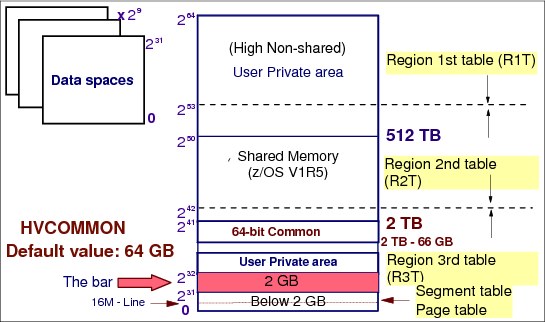
Figure 4-4 z/Architecture address space
z/Architecture address space
The two GB address in the address space is marked by a virtual line called the bar. The bar separates storage below the two GB address, called below the bar from storage above the two GB address, called above the bar. The area above the bar is intended to be used for data only, not for executing programs. Programs use the IARV64 macro to obtain storage above the bar in “chunks” of virtual storage called memory objects.
Your installation can set a limit on the use of the address space above the bar for a single address space. The limit is called the MEMLIMIT in the SMFPRMxx parmlib member.
|
Note: IBM System/370 (S/370) defined storage addresses as 24 bits in length, which meant that the highest accessible address was 16,777,215 bytes (or 224-1 bytes). The use of 24-bit addressability allowed IBM Multiple Virtual Storage (MVS)/370, the operating system (OS) at that time, to allot to each user an address space of 16 MB. Over the years, as MVS/370 gained more functions and was asked to handle more complex applications, even access to 16 MB of virtual storage fell short of user needs.
With the release of the System/370-Extended Architecture (XA) in 1983, IBM extended the addressability of the architecture to 31 bits. With 31-bit addressing, the OS (now called MVS/XA) increased the addressability of virtual storage from 16 MB to 2 GB. MVS/XA provided an address space for users that was 128 times larger than the address space provided by MVS/370. The 16 MB address became the dividing point between the two architectures, and is commonly called the line or boundary.
|
Virtual storage and 64-bit addressability
A program running in an address space can reference all of the storage associated with that address space. A program's ability to reference all of the storage associated with an address space is called addressability.
z/Architecture and z/OS operating systems
The new architecture did not require clients to change existing application programs. To maintain compatibility for existing programs, MVS/XA remained compatible for programs originally designed to run with 24-bit addressing on MVS/370, but enabled application developers to write new programs to use the 31-bit technology.
To preserve compatibility between the different addressing schemes, MVS/XA did not use the high-order bit of the address (Bit 0) for addressing. Instead, MVS/XA reserved this bit to indicate how many bits would be used to resolve an address: 31-bit addressing (Bit 0 on) or 24-bit addressing (Bit 0 off).
zSeries mainframes and 64 bit addressing
With the release of IBM zSeries mainframes in 2000, IBM further extended the addressability of the architecture to 64 bits. With 64-bit addressing, the potential size of a z/OS address space expands to a size so vast that you need new terms to describe it, as shown in Figure 4-4 on page 254.
Each address space, called a 64-bit address space, is 16 EB in size. An exabyte is slightly more than one billion gigabytes. The new address space has logically 264 addresses. It is
8 billion times the size of the former 2 GB address space, or 18,446,744,073,709,600,000 bytes.
8 billion times the size of the former 2 GB address space, or 18,446,744,073,709,600,000 bytes.
A program running on z/OS and the zSeries mainframe can run with 24-, 31-, or 64-bit addressing (and can switch among these if needed). To address the high virtual storage available with the 64-bit architecture, the program uses 64-bit-specific instructions. Although the architecture introduces unique 64-bit exploitation instructions, the program can use both 31-bit and 64-bit instructions, as needed.
Region tables and segment tables
In a 16 EB address space with 64-bit virtual storage addressing, there are three additional levels of translation tables called region tables:
•Region third table (R3T)
•Region second table (R2T)
•Region first table (R1T)
The region tables are 16 KB in length, and there are 2048 entries per table. Each region has 2 GB.
Segment tables and page table formats remain the same as for virtual addresses below the bar. When translating a 64-bit virtual address, after the system has identified the corresponding 2 GB region entry that points to the segment table, the process is the same as that described previously.
4.5 The address space concept

Figure 4-5 Address space concept
Address space concept
The range of virtual addresses that the operating system assigns to a user or separately running program is called an address space. This is the area of contiguous virtual addresses available for executing instructions and storing data. The range of virtual addresses in an address space starts at zero and can extend to the highest address permitted by the OS architecture.
Previous IBM architectures
S/370 was the first IBM architecture to use virtual storage and address space concepts. The address space size is decided by the length of the fields that keeps such addresses. Because it maps all of the available addresses, an address space includes system code and data, and user code and data. Therefore, not all of the mapped addresses are available for user code and data. The S/370 architecture used 24 bits for addressing. So, the highest accessible address in the MVS/370 was 16 MB, which was also the address space size.
With MVS/XA, the XA architecture extended to 31 bits for addressing, and the address space size went from 16 MB to 2 GB, which is 128 times bigger. The 16 MB address became the division point between the two architectures, and as mentioned is commonly called the line.
For compatibility, programs running in MVS/370 should run in MVS/XA, and new programs should be able to use the new technology. So, the high-order bit of the address (4 bytes) is not used for addressing, but rather to indicate to the hardware how many bits are used to solve an address: 31 bits (bit 32 on) or 24 bits (bit 32 off).
However, the use of multiple virtual address spaces in z/OS provides special benefits. Virtual addressing permits an addressing range that is greater than the main storage capabilities of the system. The use of multiple virtual address spaces provides this virtual addressing capability to each job in the system by assigning each job its own separate virtual address space. The potentially large number of address spaces provides the system with a large virtual addressing capacity.
z/OS z/Architecture
With z/OS, the z/Architecture extended to 64 bits and the address space size went from 2 GB to 16 Exabytes, which is 8 billion times bigger. As mentioned, the area above 2 GB address is called the bar. The addresses above the bar are used for data only.
4.6 Addressing mode and residence mode

Figure 4-6 Addressing mode and residence mode
Addressing mode and residence mode
MVS/XA introduced the concept of addressing mode (AMODE). AMODE is a program attribute to indicate which hardware addressing mode should be active to solve an address; that is, how many bits are to be used for solving and dealing with addresses:
•AMODE=24 indicates that the program can address up to 16 M virtual addresses.
•AMODE=31 indicates that the program can address up to 2 G virtual addresses.
•AMODE=64 indicates that the program can address up to 16 Exa virtual addresses (only in z/Architecture).
Residency mode
The concept of residency mode (RMODE) is used to indicate where a program is to be placed in the virtual storage (by z/OS program management) when the system loads it from DASD:
•RMODE=24 indicates that the module must reside below the 16 MB virtual storage line. Among the reasons for RMODE24 is that the program is AMODE24, the program has control blocks that must reside below the line.
•RMODE=ANY indicates that the module can reside anywhere in virtual storage, but preferentially above the 16 MB virtual storage line. Because of this, such an RMODE is also called RMODE 31. Note that in z/OS there is no RMODE=64, because the virtual storage above 2 GB is not suitable for programs, only data.
Addressing mode
AMODE is a program attribute that can be specified (or defaulted) for each control section (CSECT), load module, and load module alias. AMODE states the addressing mode that is expected to be in effect when the program is entered. AMODE can have one of the following values:
•AMODE 24. The program is designed to receive control in 24-bit addressing mode.
•AMODE 31. The program is designed to receive control in 31-bit addressing mode.
•AMODE ANY. The program is designed to receive control in either 24-bit or 31-bit addressing mode.
|
Note: AMODE and RMODE are load module attributes assigned when load modules are created by the Binder program and are placed in load module’s directory entry in a partitioned data set.
|
AMODE and RMODE combinations at execution time
At execution time, there are only three valid AMODE/RMODE combinations:
•AMODE 24, RMODE 24, which is the default
•AMODE 31, RMODE 24
•AMODE 31, RMODE ANY
The ATTACH, ATTACHX, LINK, LINKX, XCTL, and XCTLX macros give the invoked module control in the AMODE previously specified. However, specifying a particular AMODE does not guarantee that a module that gets control by other means will receive control in that AMODE. For example, an AMODE 24 module can issue a BALR to an AMODE 31, RMODE 24 module. The AMODE 31 module will get control in 24-bit addressing mode.
4.7 Storage managers

Figure 4-7 The storage component managers
Storage managers
In a z/OS system, storage is managed by the following z/OS components:
•Virtual storage manager (VSM)
•Real storage manager (RSM)
•Auxiliary storage manager (ASM)
Virtual storage manager
Virtual storage is managed by the VSM. The main function of VSM is to control the use
of virtual storage addresses by programs. Each installation can use virtual storage parameters (at data set SYS1.PARMLIB) to specify how certain virtual storage areas are to be allocated to programs. These parameters have an effect on main storage use and overall system performance.
of virtual storage addresses by programs. Each installation can use virtual storage parameters (at data set SYS1.PARMLIB) to specify how certain virtual storage areas are to be allocated to programs. These parameters have an effect on main storage use and overall system performance.
VSM keeps track of the map of virtual storage for each address space. In so doing, it sees an address space as a collection of 256 subpools, which are logically related areas of virtual storage identified by the numbers 0 to 255. Being logically related means the storage areas in a subpool share characteristics:
•Share a storage protect key
•Whether they are fetch protected, pageable, or swappable
•Where they must reside in virtual storage (above or below 16 MB)
•Whether they can be shared by more than one task
Real storage manager
RSM keeps track of the contents of main storage. It manages the paging activities, such as page-in, page-out, page stealing, and helps with swapping an address space in or out. RSM also performs page fixing, which is marking pages as unavailable for stealing.
Auxiliary storage manager
ASM controls the use of page data sets and the implicit paging I/O operation. As a system programmer, you are responsible for the size and the performance of the page data sets. The ASM uses the system's page data sets to keep track of auxiliary storage slots:
•Slots for virtual storage pages that are not in main storage frames
•Slots for pages that do not occupy frames but, because the frame's contents have not been changed, the slots are still valid
When a page-in or page-out is required, ASM works with RSM to locate the proper main storage frames and auxiliary storage slots.
4.8 Virtual storage manager

Figure 4-8 Virtual storage manager
Virtual storage manager
VSM is the z/OS component that manages virtual storage. Its main function is to control the use of virtual storage addresses. Virtual storage enables you to write large programs without the need for complex overlay structures.
The existence of an address space does not imply that all virtual addresses are automatically available to programs. Virtual storage addresses must be requested by programs through the use of the GETMAIN or STORAGE OBTAIN macros and returned to the VSM using the FREEMAIN or STORAGE RELEASE macro. The following list describes VSM functions:
•Allocate and release blocks of virtual storage on request by programs.
•Ensure that main storage frames exist for naturally fixed pages, such as system queue area (SQA), local SQA (LSQA), common service area (CSA).
•Maintain storage use information by generating IBM System Management Facility (SMF) records.
•Associate a storage protection key with each virtual storage block requested. This function is provided through the GETMAIN and STORAGE macros. See ABCs of z/OS System Programming Volume 10, SG24-6990, for more information about storage protection.
VSM also provides services that are especially useful when determining available storage, coding recovery procedures, or specifying areas to be included in a dump, as listed here:
•VSMREGN macro. List the starting address and the size of the private area regions associated with a given program (task).
•VSMLOC macro. Verify that a given area has been allocated through a GETMAIN or STORAGE macro.
•VSMLIST macro. List the ranges of virtual storage allocated in a specified area.
4.9 Real storage manager
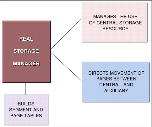
Figure 4-9 Real storage manager
Real storage manager
RSM is the z/OS component that controls the usage of main storage frames. RSM acts together with ASM to support the virtual storage concept, and with VSM to ensure that a page on which GETMAIN has been run is backed up in a main storage frame. Furthermore, RSM establishes many services to other components and application programs to manipulate the status of pages and frames. RSM functions include the following tasks:
•Allocate frames for pages located in slots during page-in operations.
•Allocate main storage for page fixing. Fixing a page in a frame means that the page will never be stolen from main storage even if there is a lack of frames. The reason justifying such functionality is availability, not performance.
•Allocate frames to satisfy GETMAIN requests for SQA, LSQA, and CSA (pages naturally fixed).
•Build segment and page tables. These tables are used to translate a virtual address to a real address.
•Work with z/OS Workload Manager (WLM) in page swapping, page stealing, and the unreferenced interval count (UIC) calculation process.
4.10 Auxiliary storage manager
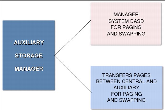
Figure 4-10 Auxiliary Storage Manager
Auxiliary storage manager
ASM is a z/OS component responsible for transferring virtual pages between central frames and auxiliary storage slots (page data sets). This is done as either a paging operation (one page at time), or as a physical swapping operation (an address space, all pages at a time). ASM manages the transfer by initiating the I/O and by maintaining tables to reflect the current status of the slots. This status includes the location of each page in each slots.
To page efficiently and expediently, ASM divides the pages into classes, namely pageable link pack area (PLPA), common, and local. There is at least one page data set for each class. Contention is reduced when these classes of pages are placed on different physical devices. In addition, output to VIO devices can be stored in local paging data sets. VIO are user temporary data sets allocated in central and auxiliary storage. Page data sets are created and formatted by the system programmer through the DEFINE IDCAMS command.
ASM attempts to maximize page I/O efficiency by incorporating a set of algorithms to distribute the I/O load evenly (through the local page data sets). In addition, every effort is made to keep the system operable in situations where a shortage of a specific type of slots exists. ASM selects a local page data set for page-out from its available page data sets. ASM selects these data sets in a circular order in each type of data set, subject to the availability of free space and the device response time.
If the address space is physically swapped out directly from main storage to auxiliary storage, ASM reads and writes these working set pages in parallel. Since z/OS V1R8, there is no more physical swapping. See 4.11, “Paging and swapping” on page 266 for more information.
4.11 Paging and swapping
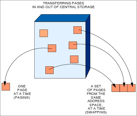
Figure 4-11 Paging and swapping concepts
Paging and swapping
Paging is the movement of pages between main storage frames and auxiliary storage slots.
There are two types of paging operations:
•Page-in, which flows from a slot to a frame. It is caused by a page fault. A page fault is an interrupt caused by the hardware in charge of translating a virtual address into a real address. The page fault happens because the page is not currently mapped to a frame. RSM gains control and, through ASM, provides a page-in operation to retrieve the page from auxiliary storage.
•Page-out, which flows from a frame to a slot. It is caused when a changed page needs to be stolen from main storage because this memory is under contention. RSM calls ASM to schedule the paging I/O necessary to send these pages to auxiliary storage.
Swapping and the working set
As mentioned, swapping is the process of transferring all of the pages of an address space between main storage and auxiliary storage. A swapped-in address space is active, having pages in main storage frames and pages in auxiliary storage slots. A swapped-out address space is inactive; the address space resides on auxiliary storage and cannot execute until it is swapped in.
Swapping is the primary function used by WLM (a z/OS component in charge of performance) to exercise control over the distribution of resources and system throughput. One reason for swapping is, for example, pageable storage shortages. There are two types of swapping:
Physical swapping Transferring all pages in an address space between main storage and auxiliary storage.
A physical swapped-in address space is an active one (its programs can be executed) that has pages in main storage and pages in auxiliary storage.
A physical swapped-out address space is an inactive one having all pages in auxiliary storage, so it cannot execute its programs until it is swapped-in.
Logical swapping To reduce the processor and channel subsystem overhead involved during a physical swap needing to access auxiliary storage, WLM performs logical swaps where possible.
In a logical swap, LSQA fixed frames and recently referenced frames are kept in main storage (in contrast to physical swaps, where these frames are moved to auxiliary storage). Address spaces that are swapped for wait state conditions are the best candidates for logical swaps. Since z/OS 1.8, all swaps are logical.
4.12 Auxiliary page data sets

Figure 4-12 Paging to auxiliary data sets
Auxiliary page data sets
Auxiliary page data sets are formatted in slots. They should contain pages that for various reasons are not to stay in main storage frames. To page efficiently and expediently, ASM divides the pages of the system into classes, namely PLPA, common, and local. Contention is reduced when these classes of pages are placed on different physical devices. Multiple local page data sets are preferable.
Although the system requires only one local page data set, performance improvement can be obtained when local page data sets are distributed across more than one device, even though other devices might be large enough to hold the entire amount of necessary page space. The PLPA and common page data sets are both required data sets, and there can be only one of each. Spillage back and forth between the PLPA and common page data sets is permissible, but, in the interest of performance, only spilling from PLPA to common is to be permitted. The page data set classes are as follows:
PLPA page data set This unique and required page data set contains pageable link pack area pages. See “Link pack area” on page 282 for more information about this topic.
Common page data set This unique and required page data set contains the CSA non-fixed virtual pages of the system common area. See “Common service area” on page 280 for more information about this topic.
Local page data sets These contain the private area pages of all address space pages, data spaces, and any VIO data sets. To better distribute the paging activity load on different volumes and controllers, you can have several local page data sets.
|
Tip: Peaks in main storage demand can occur during system operation, resulting in heavy use of local page data set slots. To address this situation, local page data sets can be dynamically added to and deleted from the paging configuration without restarting the system.
|
4.13 System z Flash Express

Figure 4-13 System z Flash Express
System z Flash Express
System z Flash Express, an optional priced feature available with the zEC12 and zBC12, is a Peripheral Component Interconnect Express (PCIe) I/O adapter with NAND flash solid state drives.
Flash memory is a non-volatile computer storage technology. It was introduced on the market decades ago. Flash memory is commonly used today in memory cards, Universal Serial Bus (USB) flash drives, solid-state drives (SSDs), and similar products for general storage and transfer of data.
An SSD, sometimes called a solid-state disk or electronic disk, is a data storage device that uses integrated circuit assemblies as memory to store data persistently. SSD technology uses electronic interfaces compatible with traditional block I/O hard disk drives (HDDs). SSDs do not employ any moving mechanical components.
This characteristic distinguishes them from traditional magnetic disks, such as HDDs, which are electromechanical devices that contain spinning disks and movable read/write heads. With no seek time or rotational delays, SSDs can deliver substantially better I/O performance than HDDs. Flash SSDs demonstrate latencies that are 10 - 50 times lower than the fastest HDDs, often enabling dramatically improved I/O response times.
The Flash Express adapters are ordered in pairs, and each pair provides up to 1.4 terabytes (TB) of usable storage. The maximum of four pairs installed provides up to 5.6 TB of storage. Flash Express is a faster paging device when compared to auxiliary storage on traditional hard disk drives. Flash Express is supported by z/OS V1R13 and above, with the
z/OS V1R13 RSM Enablement Offering web deliverable installed. It is fully supported by
z/OS V2R1.
z/OS V1R13 RSM Enablement Offering web deliverable installed. It is fully supported by
z/OS V2R1.
4.14 Storage-class memory on System z Flash Express

Figure 4-14 Paging to auxiliary data sets
Storage-class memory on System z Flash Express
The storage provided by these adapters is called storage-class memory (SCM). When enabled, SCM is used by z/OS for paging (4K and larger pages), caching of PLPA pages, and for staging of IBM System Storage® SAN Volume Controller (SVC) dumps.
You can use the Flash Express allocation windows on the Support Element (SE) or Hardware Management Console (HMC) to define the initial and maximum amount of Flash Express available to an LPAR. The maximum memory that is allocated to an LPAR can be dynamically changed. On z/OS, this process can also be done by using an operator command. Flash memory can also be configured offline to an LPAR.
Flash Express is used by the ASM with paging data sets to satisfy page-out and page-in requests received from the RSM. It supports 4 KB and 1 MB page sizes. ASM determines where to write a page based on space availability, data characteristics, and performance metrics. ASM still requires definition of a PLPA, common, and at least one local paging data set. VIO pages are only written to DASD because persistence is needed for warm starts.
A new PAGESCM keyword in IEASYSxx member defines the minimum amount of flash to be reserved for paging. Value can be specified in units of MB, GB, or TB. NONE indicates that the system does not use flash for paging. ALL (default) indicates all flash that is defined to the partition is available for paging.
4.15 31-bit address space map

Figure 4-15 31-bit address space map
31-bit address space map
Figure 4-15 shows the layout of the storage areas for an address space in virtual storage. Note that most of the system areas exist both below and above 16 MB, providing an environment that can support 24-bit, 31-bit, and 64-bit addressing. However, each area and its counterpart above 16 MB can be thought of as a single logical area in virtual storage.
Since the introduction of XA architecture, the address space size is 2 GB addresses because the fields keeping the virtual addresses are 31 bits in size. (See Figure 4-23 on page 288 for information about the 64-bit address space map.)
A 2 GB virtual storage address space is provided for:
•The master scheduler address space
•IBM Job Entry Subsystem (JES)
•Other system component address spaces, such as allocation, system trace, SMF, and dumping services
•Each user, batch or Time Sharing Option Extensions (TSO/E)
User address spaces
The system uses a portion of each virtual address space. Each virtual address space consists of:
•The common area below 16 MB
•The private area below 16 MB
•The extended common area above 16 MB
•The extended private area above 16 MB
Map of 31-bit address space
The virtual address space, shown in Figure 4-15 on page 272, is divided into areas (sets of addresses) according to their use. Virtual storage allocated in each address space is divided between system requirements and user requirements. z/OS itself requires space from each of the basic areas. Each virtual address space consists of:
•The common area below 16 MB addresses
•The private area below 16 MB addresses
•The extended common area above 16 MB addresses
•The extended private area above 16 MB addresses
For more information about common areas and private areas, see 4.16, “The common virtual storage area” on page 274.
Most of z/OS areas exist both below and above 16 MB, providing an environment that can support both 24-bit and 31-bit addressing. However, each area and its counterpart above 16 MB can be thought of as a single logical area in virtual storage.
Private area of storage
The portion of the user's private area in each virtual address space that is available to the user's problem programs is called the user region. The private area consists of LSQA and scheduler work area (SWA) in subpools 229, 230, and 249.
There are two types of user regions: virtual (or V=V) and real (or V=R). Virtual and real regions are mutually exclusive; private areas can be assigned to V=R or V=V, but not to both. It is the installation's responsibility to determine the type of region to which jobs are assigned.
Usually, V=R should be assigned to regions containing jobs that cannot run in the V=V environment, or that are not readily adaptable to it. Programs that require a one-to-one mapping from virtual to main storage, such as program control interruption-driven channel programs, are candidates for real regions.
Extended private area of storage
The extended private area of storage is an area above the 16 MB line that is in the 24-bit addressing area. The extended private area contains extended LSQA (ELSQA) and
extended SWA (ESWA) in subpools 229, 230, and 249, and is above the 16 MB line in the 31-bit addressing area.
extended SWA (ESWA) in subpools 229, 230, and 249, and is above the 16 MB line in the 31-bit addressing area.
4.16 The common virtual storage area

Figure 4-16 Common storage area
The common virtual storage area
The z/OS implementation of virtual storage is to have one address space per set of related programs (like a job step). The advantage of this design is isolation; any error is contained in one address space and cannot be propagated to another address space. Also, because the number of address spaces can be large, the number of virtual addresses to be used by programs is enormous.
However, such a design poses a problem: The need for communication between programs from different address spaces. To solve that problem, the common area was introduced. All address spaces in a z/OS system image share a virtual storage area known as the common area. That means that all address spaces programs in this z/OS access the same common data and the same common programs, with the same virtual address.
Common area below the 16 MB line
Each storage area in the common area (below 16 MB) has a counterpart in the extended common area (above 16 MB), except the prefixed save area (PSA). The CSA and SQA sizes are settled during the IPL, according to system initialization parameters in the SYS1.PARMLIB (IEASYSxx) system data set. The common area contains system control programs and control blocks.
The following storage areas are located in the common area:
•Prefixed storage area
This area is often referred to as low core. The PSA is a common area of virtual storage from address zero through 8191 in every address space. There is one unique PSA for every processor installed in a system.
The PSA maps architecturally fixed hardware and software storage locations for the processor. Because there is a unique PSA for each processor, from the view of a program running on z/OS, the contents of the PSA can change any time the program is dispatched on a different processor. This feature is unique to the PSA area, and is accomplished through a unique DAT manipulation technique called prefixing.
•Common service area
This portion of common area storage (addressable by all address spaces) is available to all applications. The CSA is often used to contain data frequently accessed by multiple address spaces. The size of the CSA area is established at system initialization time (IPL), and cannot change when the operating system is active.
•Pageable link pack area, fixed link pack area, and modified link pack area
This area contains the link pack areas, which are the PLPA, fixed link pack area (FLPA), and modified link pack area (MLPA), contain system-level programs that are often run by multiple address spaces. For this reason, the link pack areas reside in the common area, which is addressable by every address space, therefore eliminating the need for each address space to have its own copy of the program. This storage area is below the 16 MB boundary, and is therefore addressable by programs running in 24-bit mode.
•System queue area
This area contains system-level (key 0) data accessed by multiple address spaces. The SQA area is not pageable (fixed), which means that it resides in main storage until it is freed by the requesting program. The size of the SQA area is predefined by the installation, and cannot change when the OS is active. Yet it has the unique ability to “overflow” into the CSA area as long as there is unused CSA storage that can be converted to SQA.
•Nucleus, which is fixed and non-swappable
This is a key 0, read-only area of common storage that contains OS control programs.
4.17 z/OS nucleus

Figure 4-17 z/OS nucleus
z/OS nucleus
After the IPL and when the system is loaded, control is passed to IEAIPL00 which prepares an environment suitable for starting the programs and modules that make up the operating system, as follows:
1. It clears main storage to zeros before defining storage areas for the master scheduler.
2. It locates the SYS1.NUCLEUS data set on the SYSRES volume and loads a series of programs.
The nucleus in the common area contains the z/OS nucleus programs (kernel) and extensions to the nucleus that are initialized during IPL processing. The nucleus contains the most important z/OS programs. The nucleus RMODE24 programs reside below the 16 MB line. The nucleus RMODE31 programs reside above the 16 MB line.
Nucleus area
The nucleus area contains the nucleus load module, and extensions to the nucleus that are initialized during IPL processing. The nucleus includes a base and an architectural extension. Specify the correct architectural extension with the ARCHLVL statement in the LOADxx member of SYS1.PARMLIB for your system to run in either IBM Enterprise Systems Architecture/390 (IBM ESA/390) mode or z/Architecture mode.
Nucleus program modules
The program modules that are to be added to the nucleus area must reside as members in the SYS1.NUCLEUS data set. During the IPL process, the operator points to the device number (0250, in the example shown in Figure 4-17) of the volume containing that data set, causing the copy of the programs to be stored in memory.
The system programmer can add or delete modules from the nucleus by simply specifying the members on INCLUDE or EXCLUDE statements in the data set SYS1.PARMLIB, at member NUCLSTxx. The nucleus is always fixed in main storage (no pages from the nucleus can be stolen to page data sets slots).
|
Information: A set of tables, called nucleus module lists (NMLs), are used to identify the members in SYS1.NUCLEUS that are to be loaded into the DAT-on nucleus region. NMLs can be installed as part of an IBM product, a vendor product, or a customer user modification. Each NML contains a list of the SYS1.NUCLEUS members that are part of the same product or user modification. The NMLs are load modules that also reside in SYS1.NUCLEUS.
The NML must have a module name (CSECT name) in the form of IEANYnnn:
Y Can be either of S or C
S Stands for IBM provided NML
C Stands for customer-provided NML
nnn Is a 3-digit decimal number from 001 through 256
|
IEANxxxx example
Certain products have modules that must be incorporated into the z/OS nucleus, such as the IBM Information Management System (IBM IMS) Type 2 SVC.
|
Attention: The SYS1.NUCLEUS must not have secondary extents. z/OS cannot recognize secondary extents.
|
To incorporate the IMS Type 2 SVC into the z/OS nucleus, perform one of the following tasks:
•Bind the Type 2 SVC with the z/OS nucleus. You can bind the Type 2 SVC with the z/OS nucleus using one of the two following steps.
a. Invoking the Binder utility through a batch job
b. Creating and then performing a RECEIVE and APPLY for an SMP/E USERMOD
•Load the Type 2 SVC from SYS1.NUCLEUS using the Nucleus Module Loader facilities.
a. Create an NML that contains the list of IMS SVCs that you want loaded into the z/OS nucleus. IMS uses the IEANS001 NML.
b. Assemble and bind the Type 2 SVC into SYS1.NUCLEUS.
4.18 System queue area
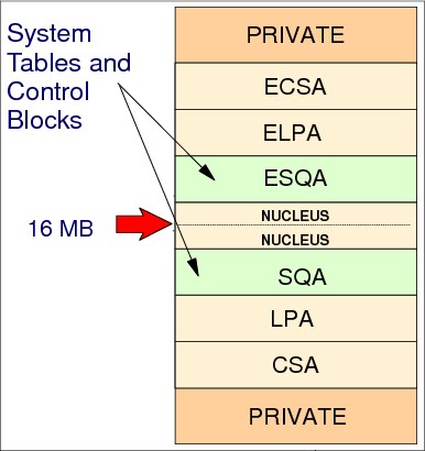
Figure 4-18 System queue area
System queue area
The system queue area (SQA) is a GETMAIN-able common area containing control blocks used by z/OS to manage transaction workloads and the use of system resources. It is a kind of virtual storage reserved area for future GETMAINs or FREEMAINs issued by authorized z/OS and non- z/OS programs. The number of active address spaces (which depends on the workload executed in the system) affects the system's use of SQA.
SQA is allocated directly below the nucleus, as shown in Figure 4-18. Extended SQA (ESQA) is allocated directly above the extended nucleus. Both allocations occur at IPL time. The size of SQA can be specified through the SQA parameter in the IEASYSxx parmlib member or like any IEASYSxx parmlib parameter, through the operator in a z/OS console at IPL:
SQA=(a,b)
This parameter specifies the sizes of the virtual SQA and ESQA. The subparameter a specifies the size of the SQA, located below 16 MB. The subparameter b specifies the size of the ESQA, located above 16 MB. These values are added to the system's minimum SQA of eight 64 KB blocks (or 512 KB) and minimum ESQA of approximately 8 MB. Both the SQA and ESQA are fixed in main storage as they are used.
Requests for SQA
When a GETMAIN for SQA/ESQA cannot be fulfilled because SQA/ESQA is full, then the SQA/ESQA overflows to CSA/extended CSA (ECSA). When SQA/ESQA pages are in use (GETMAINed), they are fixed in main storage.
Ensuring the appropriate size of SQA/ESQA and CSA/ECSA is critical to the long-term operation of z/OS. If an occupancy threshold is crossed, z/OS takes the following actions, trying to avoid an unprogrammed IPL:
•Message IRA100E displays in a z/OS console.
•No new address spaces are created.
•No new jobs are selected by initiators.
|
Note: The system also reserves additional SQA and ESQA storage for the I/O configuration. The amount of SQA and ESQA depends on the number of devices and control units installed.
Because the system adds these amounts to the SQA and ESQA blocks specified on the SQA parameter in IEASYSxx, the actual amounts of SQA and ESQA allocated might be more than you specified. Also, MVS will not round the lowest address of SQA down, or the uppermost address of ESQA up, to cause these areas to start or end on a 64 KB, page, or segment boundary.
|
4.19 Common service area

Figure 4-19 Common service area
Common service area
The CSA is a GETMAIN-able common area containing control blocks used by subsystem programs, such as JES2, Data Facility Storage Management Subsystem (DFSMS), and IBM Resource Access Control Facility (RACF), and access methods, such as Virtual Storage Access Method (VSAM). It is a sort of virtual storage-reserved area for future GETMAINs/FREEMAINs issued by such programs.
CSA/ECSA normally contains data referenced by several system address spaces, enabling address spaces to communicate by referencing the same piece of CSA data. In a sense, CSA/ECSA looks like SQA/ESQA.
CSA is allocated directly below the MLPA. ECSA is allocated directly above the extended MLPA, as shown in Figure 4-15 on page 272. If the virtual SQA/ESQA space is full, z/OS allocates additional SQA/ESQA space from the CSA/ECSA.
The size of the CSA/ECSA can be specified through the CSA parameter in the IEASYSxx member of SYS1.PARMLIB, or like any IEASYSxx parmlib parameter, through the operator in a z/OS console at IPL. The CSA contains pageable and fixed data areas that are addressable by all active virtual storage address spaces.
|
Important: If the size allocated for ESQA is too small or is used up quickly, the system attempts to steal space from ECSA. When both ESQA and ECSA are used up, the system allocates space from SQA and CSA below 16 MB. The allocation of this storage can eventually lead to a system failure. Ensuring the appropriate size of ESQA and ECSA storage is critical to the long-term operation of the system.
|
CSA/ECSA thresholds
Be aware that the following conditions can be responsible for a shortage of SQA/CSA:
•There has been storage growth beyond the previous normal range.
•Allocation of SQA or CSA is inadequate.
•The current thresholds at which the IRA100E or IRA101E messages are issued are too high for your installation.
4.20 Link pack area

Figure 4-20 Link pack area
Link pack area
The LPA and ELPA contain programs that are preloaded at IPL time in the common area, from the SYS1.LPALIB data set. These programs can be certain z/OS SVC routines, access methods code, other read-only z/OS programs (the ones not modified along its execution), and any read-only reenterable user programs selected by an installation.
Because such code is in the common area, all of these single-copy programs can be run in any address space. Their copy is not self-modifying (reentrant), so the same copy of the module can be used by any number of tasks in any number of address spaces at the same time. This reduces the demand for main storage, and lowers the program fetch overhead.
System libraries for the link pack area
The LPA is part of an address space's common area storage, and is divided into pageable, fixed, and modified sections:
•Libraries specified in SYS1.LPALIB, the LPALSTxx, or PROGxx parmlib members are loaded into PLPA. These libraries contain modules for read-only system programs, along with any read-only reenterable user programs selected by an installation that can be shared among users of the system.
•IEAFIXxx members specify the modules loaded into FLPA. This area is to be used only for modules that significantly increase performance when they are fixed rather than pageable. The best candidates for the FLPA are modules that are infrequently used, but are needed for fast response. Modules placed in FLPA are always in main storage.
•IEALPAxx members specify the modules loaded into MLPA. The MLPA is used to contain reenterable routines from authorized program facility (APF)-authorized libraries that are to be part of the pageable extension to the LPA during the current IPL. Note that the MLPA exists only for the duration of an IPL.
LPA/ELPA specifications
The LPA/ELPA size depends on the number of modules loaded in it. When modules are added to LPA, the growth in LPA can cause the common area to cross one or more segment (1 MB) boundaries. This reduces the available private area for all address spaces, even for those address spaces not using the load modules added to LPA.
All modules placed in LPA are assumed to be APF-authorized. Being APF-authorized means that a program can invoke any SVC routine that accesses protected system and private areas. Although LPA boundaries cannot be changed after IPL, it is possible to dynamically include new load modules to LPA without an IPL. In this case, z/OS issues a GETMAIN from CSA/ECSA, and uses such virtual storage area to load the load module.
The RMODE attribute of the program (load module) decides its location (LPA or ELPA). The ELPA is built above 16 MB.
Pages from modules (programs) placed anywhere in LPA are always in virtual storage. Pages from modules placed in FLPA are also always in main storage. Whether modules that are in LPA, but outside FLPA, are in main storage depends on how often they are used by all of the programs of the system, and on how much main storage is available. The more often an LPA module is used, and the more main storage that is available on the system, the more likely it is that the pages containing the copy of the module will be in main storage at any given time.
Each address space uses the same common area. Portions of the common area are paged in and out as the demands of the system change, and as new user jobs (batch or time-shared) start and old ones terminate.
4.21 31-bit address space private area
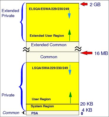
Figure 4-21 The user’s private area (user region)
31-bit address space private area
The portion of the user's private area in each virtual address space that is available to the user's problem programs is called the user region. The use of address spaces enables z/OS to maintain the distinction between the programs and data belonging to each address space. The private areas in one user’s address space are isolated from the private areas in other address spaces, and this address space isolation provides much of the OS’s security.
Private areas
There are two private areas: below the 16 MB line is the private (PVT), and above the
16 MB line is the extended private (EPVT). Their size is the complement of the common area’s size. The virtual addresses in the private area is unique to the programs running in such areas.
16 MB line is the extended private (EPVT). Their size is the complement of the common area’s size. The virtual addresses in the private area is unique to the programs running in such areas.
The private area is formed by the following areas:
•Subpools 229, 230, and 249
This area enables private storage to be obtained in the requestor's storage protect key. The area is used for control blocks that can be obtained only by authorized programs (such as z/OS) having appropriate storage protect keys.
A subpool is a virtual storage area with the same properties regarding storage key, pageable or fixed, private or common, fetch protected or not, and so on. When a program GETMAINs virtual storage addresses, it must indicate the subpool number.
•Local system queue area
This area contains tables and control blocks queues associated with the address space. LSQA is intermixed with SWA and subpools 229, 230, and 249 downward from the bottom of the CSA into the unallocated portion of the private area, as needed.
ELSQA is also intermixed, but it is allocated downward from 2 GB into the unallocated portion of the extended private area, as needed. LSQA does not take space below the top of the highest storage currently allocated to the user region.
•Scheduler work area
SWA contains control blocks that exist from task initiation to task termination. It includes control blocks and tables created during job control language (JCL) interpretation.
•A 16 KB system region area
•User region
This region is used for running user program applications (loaded at subpools 251/252) and storing user program data (subpools from 0 - 127).
When a module is loaded into the private area for an address space, the region available for other components is reduced by the amount of storage used for the module. The amount of private virtual storage that a job can use for subpools 251/252 and from 0 - 127 (the low addresses of the two private areas) can be limited through the REGION keyword on the JOB or EXEC JCL statements. Also, the region size can be controlled and overridden through the SMF exit IEFUSI. A value equal to 0 KB or 0 MB gives the job all private storage available.
4.22 Data spaces and IBM Hiperspace
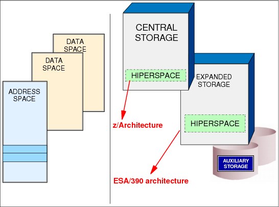
Figure 4-22 Data space management
Data spaces and IBM Hiperspace
IBM ESA/370 and MVS/ESA had improvements to relieve virtual storage constraint, bringing horizontal growth to virtual storage with data spaces (a new type of z/OS address space) and IBM Hiperspace™ (a new type of service).
The growth of processing, storage, and I/O capabilities led to a virtual storage constraint. The upward growth in virtual storage (address space size) was limited by the architecture (hardware and software).
The main difference between data spaces and Hiperspace is the way a program references data. A program references data in a data space directly, in much the same way that it references data in an address space. It addresses the data by the byte, manipulating, comparing, and performing arithmetic operations. The program uses the same instructions (such as load, compare, add, and move character) that it uses to access data in its own address space.
To reference the data in a data space, the program must be in the Address Space Control (ASC) mode called access register (AR) mode. Pointers that associate the data space with the program must be in place, and the contents of ARs that the instructions use must identify the specific data space.
Data spaces
A data space is a type of virtual storage space with a range up to 2 GB of contiguous virtual storage. The virtual storage map of a data space is quite different than an address space. The entire 2 GB is available for user data, and does not contain specific areas.
A data space can hold only data (operands accessed by instructions located in address spaces). It does not contain z/OS control blocks or programs in execution. Program code does not execute in a data space, although a program can reside in a data space as data (to be executed, however, it needs to be copied to an address space). A program can refer to data in a data space at bit level, as it does in a work file.
Hiperspace
High performance data access, known as Hiperspace, is a kind of data space created with the same RSM services used to create a data space. It provides the applications an opportunity to use expanded storage as a substitute to I/O operations. Hiperspace differs from data spaces in the following ways:
•Main storage is never used to back the virtual pages in Hiperspace, where pages are located in expanded or auxiliary storage.
•Data can be retrieved and stored between a Hiperspace and a data space only using
MVS services. This avoids the complex programming required when accessing data in a data space.
MVS services. This avoids the complex programming required when accessing data in a data space.
•Data is addressed and referred to as a 4 KB block.
Although z/OS does not support Expanded Storage when running under the z/Architecture, Hiperspace continues to operate in a compatible manner. Under z/Architecture, Hiperspace is mapped in main storage (rather than expanded) and auxiliary storage.
Programs can use data spaces and Hiperspace as described here:
•To obtain more virtual storage than a single address space gives a user.
•To isolate data from other tasks (programs) in the address space. Data in an address space is accessible to all programs executing in that address space. You might want to move data to a database or Hiperspace for security or integrity reasons. You can restrict access to data in those spaces to one or several units of work.
•To share data among programs that are executing in the same address space, or different address spaces. Rather than keeping the shared data in common areas, you can create a database or Hiperspace for the data that you want your programs to share. Use this space as a way to separate your data logically by its own particular use.
•To provide an area in which to map a data-in virtual object.
4.23 64-bit address space map

Figure 4-23 64-bit address space map
64-bit address space map
As previously mentioned, z/Architecture broke the 2 GB (31-bit) main storage limit and the 2 GB (31-bit) address limit, and moved the limit to 16 EB (64-bit). The maximum of a z/OS address space is 16 EB addresses, which makes the new address space 8 billion times the size of the former 2 GB address space. However, any new created address space in z/OS is initialized with 2 GB addresses (as it was previously), but with the potential to go beyond.
For compatibility, the layout of the virtual storage areas for an address space is the same under 2 GB. The area that separates the virtual storage area below the 2 GB address from the user private area is called the bar, as shown in Figure 4-23, and is 2 GB addresses thick. In a 64-bit virtual storage environment, the terms above the bar and below the bar are used to identify the areas between 2**31 and 2**64-1, and 0 and 2**31-1, respectively.
For example, an address in the range 0 - 7FFFFFFF is below the bar. An address in the range FFFFFFFF - 7FFFFFFF_FFFFFFFF is above the bar. This is basically an alteration to the
2 GB 31-bit terminology that related “below the line” to 24-bit storage, and “above the line” to 31-bit addresses.
2 GB 31-bit terminology that related “below the line” to 24-bit storage, and “above the line” to 31-bit addresses.
The 64-bit address space map differs from the 31-bit address space map in the following ways:
0 to 2**31 The layout is the same; see Figure 4-15 on page 272.
2**31 to 2**32 From 2 GB - 4 GB is considered the bar. Below the bar can be addressed with a 31-bit address. Above the bar requires a 64-bit address.
2**32 - 2**35 Reserved area addressable by the Java Virtual Machine (JVM) using 32-bit pointer compression.
2**35 - 2**41 The low non-shared area starts at 4 GB and goes to 2**41. A portion of this storage is designed to be used for system storage as an equivalent to LSQA below the 2 GB bar. This system area will not be copied during the fork() process when RSM copies the parent storage to the child address space.
Memory objects are allocated in the system area that starts at X’8_00000000’ - 32 GB and ends at X’28_00000000’ - 288 GB using the IARV64 macro with REQUEST=GETSTOR,LOCALSYSARES=YES.
2**41 - 2**50 The Shared Area starts at 2**41 and goes to 2**50 or higher if requested (up to 2**53).
2**50 - 2**64 The high non-shared area starts at 2**50 or wherever the shared area ends and goes to 2**64.
|
Attention: The area above the bar is designed to keep data (such as IBM DB2 buffer pool and IBM WebSphere data), and not to load modules (programs). There is no RMODE64 as a load module attribute. However, such programs running below the bar might request virtual storage above the bar and access it. To access such an address, the program must be AMODE64.
To allocate and release virtual storage above 2 GB, a program must use the services provided in the IARV64 macro. The GETMAIN, FREEMAN, STORAGE, and CPOOL macros do not allocate storage above the 2 GB address, nor do callable cell pool services.
|
Region tables
In a 16 EB address space with 64-bit virtual storage addressing, there are three additional levels of translation tables, called region tables:
•Region third table (R3T)
•Region second table (R2T)
•Region first table (R1T)
The region tables are 16 KB in length, and there are 2048 entries per table. Each region has 2 GB.
Page and segment tables
Segment tables and page table formats remain the same as for virtual addresses below the bar. When translating a 64-bit virtual address, after the system has identified the corresponding 2 GB region entry that points to the segment table, the process is the same as that described previously.
User private area
This area above the bar is intended for application data; no programs run above the bar. No system information or system control blocks exist above the bar, either. Currently there is no common area above the bar.
The user private area, as shown in Figure 4-23 on page 288, includes:
•Low private. The private area below the line.
•Extended private. The private area above the line.
•Low non-shared. The private area just above the bar.
•High non-shared. The private area above the Shared Area.
As users allocate private storage above the bar, it will first be allocated from the low non-shared area. Similarly, as the shared area is allocated, it will be allocated from the bottom up. This is done to enable applications to have both private and shared memory above the bar, and avoid additional machine cycles to perform dynamic address translation (DAT).
For virtual storage above the bar, a new JCL keyword (MEMLIMIT) is introduced on the JOB and EXEC JCL statements. For virtual storage above the bar, there is no practical limit to the amount of virtual address range that an address space can request. However, there are practical limits to the main storage and auxiliary storage needed to back the request. Therefore, a limit is placed on the amount of usable virtual storage above the bar that an address space can use at any one time.
|
Important: MEMLIMIT controls the amount of usable storage above the 2 GB line. Also, there is an exit IEFUSI that does the same.
|
4.24 Size and number notation in bytes

Figure 4-24 Size and number notation in bytes
Size and number notation in bytes
The introduction of 64-bit virtual addresses presents a new order of magnitude of numbers, so this section covers the names and raw sizes of these numbers.
In bytes, the letters K, M, G, T, P, and E denote the multipliers 2**10, 2**20, 2**30, 2**40, 2**50, and 2**60, respectively. The letters are from the International System of Units (SI) unit of measurement prefixes and their associated decimal multipliers, and stand for Kilo (10**3), Mega (10**6), Giga (10**9), Tera (10**12), Peta (10**15), and Exa (10**18). Note that Exa is 1 followed by 18 zeroes.
Kilobyte A kilobyte is 2 to the 10th power, or 1,024 bytes.
Megabyte A megabyte is 2 to the 20th power, or 1,048,576 bytes.
Gigabyte A gigabyte is 2 to the 30th power, or 1,073,741,824 bytes.
Terabyte A terabyte is 2 to the 40th power, or 1,099,511,627,776 bytes.
Petabyte A petabyte is 2 to the 50th power, or 1,125,899,906,842,624 bytes.
Exabyte An exabyte is 2 to the 60th power, or 1,152,921,504,606,846,976 bytes.
In z/Architecture, these multiplier letters do not have the SI decimal meaning. but rather represent the power of 2 closest to the corresponding power of 10. Figure 4-24 shows the names and the decimal values of these multipliers.
4.25 Segment tables and page tables in 31-bit addressing

Figure 4-25 31-bit virtual address and dynamic address translation
Virtual addressing
Main storage is viewed as a long sequence of bits. The sequence of bits is subdivided into units of 8 bits, called a byte. Each byte location in storage is identified by a unique integer starting with zero (0), called an address. Addresses are either 31-bit or 64-bit integer values.
An address space is a sequence of virtual addresses that is associated with virtual storage. The addresses are usually contiguous, but they do not need to be. A page is 4096 bytes, and is the minimum size of an address space. A program of fewer than 4096 bytes fits into a single page. All of the addresses used in a program are set up assuming that the program is loaded into main storage starting at location 0. In reality, it is not, but this assumption makes decoding the virtual address somewhat easier.
If the program size increases beyond 4096 bytes (the size of a single page), another page is allocated. It does not matter whether the newly allocated page is adjacent to the first page or a hundred pages away from it. The IBM z/Transaction Processing Facility (z/TPF) system decodes the addresses in the same way.
Segment tables and page tables
DAT is the hardware in charge of translating a virtual address during a storage reference into the corresponding real address, using translation tables (segment tables and page tables) prepared by the z/OS component RSM.
Each address space has its own segment tables and page tables. Each segment table entry has a pointer to the correlated page table. There are pointers only for those page tables having pages with GETMAINed addresses. A page table is allocated when the first page on that segment is allocated. There is a maximum of 2048 page tables.
To make this translation easier, the virtual address space is partitioned into segments, each one of 1 MB addresses. Therefore, each 2 GB address space has 2048 segments. Each segment has 256 4 KB pages. Given a virtual address, DAT finds the following information contained in the virtual address:
•Segment index (number of the segment) in the first 11 bits of the address, up to 2047 = b'111 1111 1111'= X'7FF'.
•Page index (number of the page in that segment) in the next 8 bits, up to 255 = b'1111 1111'= X'FF'.
•Byte index (displacement in the page) in the last 12 bits, up to 4095 = b'111111111111' = X'FFF'.
For more information about this topic, see Figure 4-15 on page 272.
Segment number
The segment number is mapped with an entry into a segment table (one entry per segment), with 2048 entries. Each entry is identified from 0 to 2047. The entry 0 refers to segment 0, the entry 1 refers to segment 1, and so on.
Each address space has one segment table. Each entry in a segment table points to a page table that maps each page of a segment in into an entry table. The system uses a page table with 256 entries.
Because each page is 4 KB, each address space segment has 256 pages. Each entry identifies each page in that segment. Therefore, entry 0 refers to the first page of the segment, entry 1 refers to the second page in the same segment, and so on. The page table entry has the real address of the frame mapping the page, or an invalid bit, when this mapping does not happen. This invalid bit causes a program interrupt known as a page fault. When a page fault occurs, the contents of the page are in a auxiliary storage slot on DASD.
4.26 Program status word format
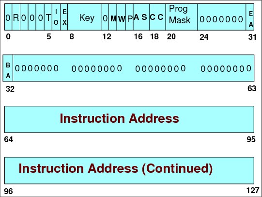
Figure 4-26 Program status word format
Program status word
The current program status word (PSW) in the central processor unit (CPU) contains information required for the execution of the currently active program. The PSW is 128 bits in length and includes the instruction address, condition code, and other control fields. In general, the PSW is used to control instruction sequencing, and to hold and indicate much of the status of the CPU in relation to the program currently being executed.
Additional control and status information is contained in control registers and permanently assigned storage locations. The status of the CPU can be changed by loading a new PSW or part of a PSW.
PER mask - R (bit 1)
Bit 1 controls whether the CPU is enabled for interrupts associated with program-event recording (PER). When the bit is zero, no PER event can cause an interruption. When the bit is one, interruptions are permitted, subject to the PER-event-mask bits in control register 9.
DAT mode - T (bit 5)
Bit 5 controls whether implicit dynamic address translation of logical and instruction addresses used to access storage takes place. When the bit is zero, DAT is off, and logical and instruction addresses are treated as real addresses. When the bit is one, DAT is on, and the dynamic-address-translation mechanism is invoked.
I/O mask - IO (bit 6)
Bit 6 controls whether the CPU is enabled for I/O interruptions. When the bit is zero, an I/O interruption cannot occur. When the bit is one, I/O interruptions are subject to the I/O-interruption subclass-mask bits in control register 6. When an I/O-interruption subclass-mask bit is zero, an I/O interruption for that I/O-interruption subclass cannot occur. When the I/O-interruption subclass-mask bit is one, an I/O interruption for that I/O-interruption subclass can occur.
External mask - EX (bit 7)
Bit 7 controls whether the CPU is enabled for interruption by conditions included in the external class. When the bit is zero, an external interruption cannot occur. When the bit is one, an external interruption is subject to the corresponding external subclass-mask bits in control register 0:
•When the subclass-mask bit is zero, conditions associated with the subclass cannot cause an interruption
•When the subclass-mask bit is one, an interruption in that subclass can occur.
PSW key (bits 8-11)
Bits 8-11 form the access key for storage references by the CPU. If the reference is subject to key-controlled protection, the PSW key is matched with a storage key when information is stored, or when information is fetched from a location that is protected against fetching. However, for one of the operands of each of MOVE TO PRIMARY, MOVE TO SECONDARY, MOVE WITH KEY, MOVE WITH SOURCE KEY, and MOVE WITH DESTINATION KEY, an access key specified as an operand is used rather than the PSW key.
Processor-check mask - M (bit 13)
Bit 13 controls whether the CPU is enabled for interruption by processor-check conditions. When the bit is zero, a processor-check interruption cannot occur. When the bit is one, processor-check interruptions due to system damage and instruction-processing damage are permitted, but interruptions due to other processor-check-subclass conditions are subject to the subclass-mask bits in control register 14.
Wait state - W (bit 14)
When bit 14 is one, the CPU is waiting; that is, no instructions are processed by the CPU, but interruptions can occur. When bit 14 is zero, instruction fetching and execution occur in the normal manner. The wait indicator is on when the bit is one. When in wait state, the only way of getting out of that state is through an Interruption, or by an IPL (a z/OS boot).
Certain bits, when off in the current PSW, place the CPU in a disabled state; the CPU does not accept Interrupts. So when z/OS, for any error reason (software or hardware) decides to stop a CPU, it sets the PSW to the Disable and Wait state, forcing an IPL to restore the CPU back to the running state.
Problem state - P (bit 15)
When bit 15 is one, the CPU is in the problem state. When bit 15 is zero, the CPU is in the supervisor state. In the supervisor state, all instructions are valid.
In the problem state, only those instructions are valid that provide meaningful information to the problem program and that cannot affect system integrity; such instructions are called unprivileged instructions.
The instructions that are never valid in the problem state are called privileged instructions. When a CPU in the problem state attempts to execute a privileged instruction, a privileged-operation exception is recognized. Another group of instructions, called semi-privileged instructions, are executed by a CPU in the problem state only if specific authority tests are met; otherwise, a privileged-operation exception or a special-operation exception is recognized.
Address-space control -AS (bits 16-17)
Bits 16 and 17, in conjunction with PSW bit 5, control the translation mode.
Condition code - CC (bits 18-19)
Bits 18 and 19 are the two bits of the condition code. The condition code is set to 0, 1, 2, or 3, depending on the result obtained in executing certain instructions. Most arithmetic and logical operations, and various other operations, set the condition code. The instruction BRANCH ON CONDITION can specify any selection of the condition-code values as a criterion for branching.
The part of the CPU that executes instructions is called the arithmetic logic unit (ALU). The ALU has internally four bits that are set by certain instructions. At the end of these instructions, this 4-bit configuration is mapped into bits 18 and 19 of the current PSW.
As an example, the instruction COMPARE establishes a comparison between two operands. The result of the comparison is placed in the CC of the current PSW, as follows:
•If CC=00, then the operands are equal.
•If CC=01, then first operand is lower.
•If CC=10, then first operand is greater.
To test the contents of a CC (set by a previous instruction), use the BRANCH ON CONDITION (BC) instruction. It contains an address of another instruction (branch address) to be executed, depending on the comparison of the CC and a mask M. The instruction address in the current PSW is replaced by the branch address if the condition code has one of the values specified by M; otherwise, normal instruction sequencing proceeds with the normal updated instruction address. The following list includes the types of codes:
•Condition code (bits 18, 19 PSW).
•Return code. A code associated with how a program ended.
•Completion code. A code associated with how a task ended.
•Reason code. A code passed in the GPR 15 detailing how a task ended.
Program Mask (bits 20-23)
During the execution of an arithmetic instruction, the CPU might find an unusual (or error) condition, such as overflows, loss of significance, or underflow. In such cases, the CPU generates a program interrupt.
When this interrupt is treated by z/OS, usually the current task is abnormally ended (ABEND). However, in certain situations, programmers do not want an ABEND, so by using the instruction SET PROGRAM MASK, they can mask such interrupts by setting various program mask bits to OFF. Each bit is associated with one type of condition:
•Fixed point overflow (bit 20)
•Decimal overflow (bit 21)
•Exponent underflow (bit 22)
•Significance (bit 23)
The active program is informed about these events through the condition code posted by the instruction where the events described happened.
The contents of the CPU can be totally changed by two events:
•Loading a new PSW from storage along an interruption
•Executing the instruction LPSW, which copies 128 bits from memory to the current PSW
Extended addressing mode - EA, BA (bits 31-32)
The combination of bits 31 and 32 identify the addressing mode (24, 31, or 64) of the running program. Bit 31 controls the size of effective addresses and effective-address generation in conjunction with bit 32, the basic-addressing-mode bit. When bit 31 is zero, the addressing mode is controlled by bit 32. When bits 31 and 32 are both one, 64-bit addressing is specified.
4.27 31-bit virtual address

Figure 4-27 Translating 31-bit vIrtual addresses
Virtual address
A virtual address identifies a location in virtual storage. When a virtual address is used for an access to main storage, it is translated by means of DAT to one of the following types of address:
•A real address, which is then further converted by prefixing to an absolute address
•Directly to an absolute address
Address size
An address size refers to the maximum number of significant bits that can represent an address. Three sizes of addresses are provided: 24-bit, 31-bit, and 64-bit:
•A 24-bit address can accommodate a maximum of 16,777,216 bytes (16 MB).
•A 31-bit address can address 2,147,483,648 bytes (2 GB).
•A 64-bit address can address 18,446,744,073,709,551,616 bytes (16 EB).
|
Information: A 24-bit or 31-bit virtual address is expanded to 64 bits by appending 40 zeros (24-bit) or 33 zeros (31-bit) on the left before it is translated by means of the DAT process.
A 24-bit or 31-bit real address is similarly expanded to 64 bits before it is transformed by prefixing.
A 24-bit or 31-bit absolute address is expanded to 64 bits before main storage is accessed. Therefore, the 24-bit address always designates a location in the first 16 MB block of the 16 EB storage addressable by a 64-bit address, and the 31-bit address always designates a location in the first 2 GB block.
|
31-bit virtual addresses
A virtual address contains the following sections:
•Bit 33 - 43 identifies the segment number (segment index).
•Bit 44 - 51 identifies the page number in that segment (page index).
•Bit 52 - 63 indicates the displacement of the data in that page (byte index).
To translate a 31-bit virtual address (2 GB) into a real address, DAT uses the following bits:
•Bits 33 - 43 as an index in the segment table to find the entry that points to the page table address of that segment
•Bits 44 - 51 as an index in the page table entry that has the frame real address, or that has the invalid bit turned on
•Bits 52 - 63 as the displacement of the data from the beginning of the frame, to be added to the frame real address to get the real address
|
Information: The size of effective addresses is controlled by bits 31 and 32 of the PSW, the extended-addressing mode bit (bit 31) and the basic-addressing-mode bit (bit 32), respectively. When bits 31 and 32 are both zero, the CPU is in the 24-bit addressing mode, and 24-bit operand and instruction-effective addresses are specified.
When bit 31 is zero and bit 32 is one, the CPU is in the 31-bit addressing mode, and 31-bit operand and instruction-effective addresses are specified.
When bits 31 and 32 are both one, the CPU is in the 64-bit addressing mode, and 64-bit operand and instruction-effective addresses are specified. See Figure 4-26 on page 294 and “Extended addressing mode - EA, BA (bits 31-32)” on page 297 for more information about this topic.
|
4.28 64-bit virtual address translation

Figure 4-28 64-bit dynamic address translation
64-bit virtual address translation
In a 16 EB address space with 64-bit virtual storage addressing, there are three additional levels of translation tables, called region tables. They are known as the region third table (R3T), the region second table (R2T), and the region first table (R1T). The region tables are 16 KB in length, and there are 2048 entries per table. Each region has 2 bytes. Figure 4-28 illustrates the table hierarchy and sizes.
|
Important: Consider the following points:
•When the first GETMAIN is obtained above the bar, RSM creates the R3T. The R3T table has 2048 segment table pointers, and it provides addressability to the low 4 TB addresses.
•When virtual storage addresses greater than 4 TB are GETMAINed, an R2T is created. An R2T has 2048 R3T table pointers, and it provides addressability to 8 PB addresses.
•When virtual storage greater than 8 PB is GETMAINed, an R1T is created. The R1T has 2048 R2T table pointers, and it provides addressability to 16 EB.
|
Segment table and page tables
Segment table (SGT) and page table (PGT) formats remain the same as for virtual addresses below the bar. When translating a 64-bit virtual address, and after you have identified the corresponding 2 GB region entry that points to SGT, the process is the same as described previously.
RSM only creates the additional levels of region tables when it is necessary to back virtual storage that is mapped. The region tables are not built until a translation exception occurs.
For example, if an application requests 60 PB of virtual storage, then the necessary R2T, R3T, SGT, and PGTs are only created if they are needed to back a referenced page.
Up to five lookup tables can be needed by DAT to accomplish translation, but the translation only starts from the table that provides translation for the highest usable virtual address in the address space.
4.29 Translating a 64-bit virtual address
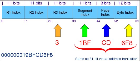
Figure 4-29 Translating a virtual address
Translating a 64-bit virtual address
Up to three additional levels of DAT tables, called region tables, are used for translating 64-bit virtual addresses.
To translate a 64-bit virtual address into a real address, DAT uses:
•Bits 0 - 10 are the first region index into the R1T table.
•Bits 11 - 21 are the second region index into the R2T table.
•Bits 22 - 32 are the third region index into the R3T table.
•Bits 33 - 43 are the segment index into the SGT.
•Bits 44 - 51 are the page index into the PGT.
•Bits 52 - 63 indicate the data displacement into the page itself.
With 64-bit virtual addressing, there are now three more 11-bit region indexes to the three region tables, as illustrated in Figure 4-29.
RSM only creates the additional levels of region tables when it is necessary to back storage that is mapped.
4.30 z/OS 1 MB and 2 GB Large Pages

Figure 4-30 1 MB and 2 GB large pages
1 MB and 2 GB Large Pages
z/OS V1R9 with a z10 or later System z server supports 1 MB fixed pages.
z/OS V1R13 or later with the RSM Enablement Offering for z/OS R13, an IBM zEnterprise EC12 (zEC12) or IBM zEnterprise BC12 (zBC12), and the Flash Express feature supports pageable large (1 MB) pages.
z/OS V1R13 or later with the RSM Enablement Offering for z/OS R13, a zEC12 or zBC12, and authorized program analysis report (APAR) OA40967 provides support for 2 GB fixed pages.
The IEASYSxx LFAREA parameter specifies the amount of real storage to be made available for 1 MB and 2 GB large pages. All 1 MB and 2 GB pages are backed by contiguous 4 KB real storage frames, and are allocated from real storage as specified by the LFAREA parameter.
If the system becomes constrained by a lack of sufficient 4 KB pages to handle workload demand, it can use free 1 MB large pages to back 4 KB page requests, enabling the system to react dynamically to changing system storage frame requirements. Virtual storage for large pages are allocated from above the 2 GB bar.
The RSM Enablement Offering for z/OS R13 and a description of the new functions can be found on the following website:
Details on the specification of the LFAREA keyword are documented in the MVS Initialization and Tuning Reference, SA23-1380.
4.31 System initialization (IPL process)

Figure 4-31 System initialization (IPL process)
Initialization process at first IPL
At the first IPL after system installation, the system automatically loads the PLPA from the LPALST concatenation. The page data sets for this IPL are those specified in the IEASYS00 parmlib member, plus any specified by the operator.
After the first IPL, you must run IFCDIP00 to initialize the LOGREC data set. This routine must also be run whenever the LOGREC data set is reallocated.
Types of IPL
There are several types of IPLs:
Cold start This refers to any IPL that loads (or reloads) the PLPA, but does not preserve VIO data set pages. The first IPL after system installation is always a cold start, because the PLPA is initially loaded. Subsequent IPLs are cold starts when the PLPA is reloaded, either to alter its contents or to restore its contents if they were destroyed.
Quick start This refers to any IPL that does not reload the PLPA and does not preserve VIO data set pages. The system resets the page and segment tables to match the last-created PLPA.
Warm start This refers to any IPL that does not reload the PLPA, but preserves journaled VIO data set pages.
System initialization
To tailor the system's storage parameters, you need a general understanding of the system initialization (IPL) and storage initialization processes.
The system initialization process prepares the system control program (z/OS) and its environment to perform work for the installation. The process essentially consists of the following tasks:
•System and storage initialization (virtual, real, and auxiliary), including the creation of the common area and the system component address spaces
•Master scheduler initialization and subsystem initialization
When the system is initialized and the JES is active, the installation can submit jobs and start other address spaces through the START, LOGON, or MOUNT commands.
Also, z/OS creates system component address spaces. z/OS establishes an address space for the master scheduler (*MASTER* address space), and other system address spaces for various subsystems and system components.
|
Important: Several z/OS components do not need a specific address space. System component address spaces include:
•Program call/authorization for cross-memory communications
•System trace
•Global resource serialization
•Dumping services
|
4.32 z/OS address spaces
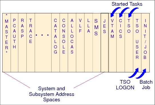
Figure 4-32 System and subsystem address spaces in z/OS
z/OS address spaces
When you start z/OS, master scheduler initialization routines initialize system services, such as the system log and communications task, and start the master scheduler address space (*MASTER*). Each address space created has a a number associated to it, known as the address space identifier (ASID). Because the master scheduler is the first address space created in the system, it becomes address space number one (ASID=1). Other system address spaces are then started during the initialization process of z/OS.
Next, subsystem address spaces are started. The master scheduler starts the job entry subsystem (JES2 or JES3). JES is the primary job entry subsystem. Then other defined subsystems are started. All subsystems are defined in SYS1.PARMLIB, member IEFSSNxx. These subsystems are secondary subsystems. See “Subsystem definitions” on page 308 for more information about these subsystems.
System component address spaces
In addition to initializing system areas, MVS establishes system component address spaces. MVS establishes an address space for the master scheduler (the master scheduler address space) and other system address spaces for various subsystems and system components.
Several of the component address spaces are shown in Figure 4-33.
|
*MASTER* Master address space
ABARS, ABARxxxx 1 to 15 DFSMShsm secondary address spaces to perform
aggregate backup or aggregate recovery processing.
ALLOCAS Allocation services and data areas
ANTMAIN Concurrent copy support
APPC APPC/MVS component
ASCH APPC/MVS scheduling
CATALOG Catalog functions. Also known as CAS (catalog address space).
BPXOINIT z/OS UNIX System Services
CONSOLE Communications task
DFM Distributed File Manager/MVS
DFMCAS Distributed File Manager/MVS
DLF Data lookaside facility
DUMPSRV Dumping services
HSM DFSMShsm
HZSPROC IBM Health Checker for z/OS
FTPSERVE FTP server(s); can be user-specified names.
GDEDFM For each Distributed File Manager/MVS user conversation that is
active, an address space named GDEDFM is created.
GRS Global resource serialization
IEFSCHAS Scheduler address space
IOSAS I/O supervisor, ESCON, I/O recovery
IXGLOGR System logger
JES2 JES2
JES2AUX JES2 additional support
JES2MON JES2 address space monitor
JES3 JES3
JES3AUX JES3 additional support
JES3DLOG JES3 hardcopy log (DLOG)
JESXCF JES common coupling services address space
LLA Link list
NFS DFSMS/MVS Network File System address space
OAM DFSMSdfp Object Access Method
OMVS z/OS UNIX System Services
PCAUTH Cross-memory support
PORTMAP Portmapper function
RASP Real storage manager (includes advanced address space facilities
support)
RMM DFSMSrmm
RRS Resource recovery services (RRS)
SMF System management facilities
SOM SOMobjects
SMS Storage management subsystem
SMSPDSE1 Optional restartable PDSE address space. If the SMSPDSE1 address
space is started, SMSPDSE manages PDSEs in the LINKLST
concatenatio and SMSPDSE1 manages all other PDSEs.
SMSVSAM VSAM record level sharing
TCPIP TCP/IP for MVS
TRACE System trace
VLF Virtual lookaside facility
XCFAS Cross system coupling facility
VTAM VTAM
WLM Workload management
|
Figure 4-33 System component address spaces
4.33 Subsystem definitions

Figure 4-34 Subsystem definitions in SYS1.PARMLIB
Subsystem definitions
A subsystem is a service provider that performs one function or many functions, but does nothing until it is requested. Although the term “subsystem” is used in other ways, in this document a subsystem must be the master subsystem, or be defined to MVS using the IEFSSNxx parmlib member. You can use either the keyword format or positional format of the IEFSSNxx parmlib member. It is preferable to use the keyword format, because it enables you to define and dynamically manage your subsystems.
Subsystem initialization
Subsystem initialization is the process of readying a subsystem for use in the system. The IEFSSNxx members of SYS1.PARMLIB contain the definitions for the primary subsystems (such as JES2 or JES3) and the secondary subsystems (such as storage management subsystem (SMS), IBM CICS, DB2, and so on). For detailed information about the data contained in IEFSSNxx members for secondary systems, see the installation manual for the specific subsystem.
IEFSSNxx parmlib member
The IEFSSNxx parmlib member enables you to specify the following items:
•The subsystem initialization routine to be given control during master scheduler initialization
•The input parameter string to be passed to the subsystem initialization routine
•A primary subsystem name and whether you want it started automatically
|
Important: The order in which the subsystems are initialized depends on the order in which they are defined in the IEFSSNxx parmlib member on the SSN parameter. Unless you are starting the SMS, start the primary subsystem (JES) first.
Note: The SMS is the only subsystem that can be defined before the primary subsystem.
|
Types of subsystems
There are two types of subsystems:
•The primary subsystem, which is the job entry subsystem that MVS uses to complete work. It can be either JES2 or JES3.
•Secondary subsystems, which provide functions as needed by IBM products, vendor products, or the installation.
MVS communicates with subsystems through the subsystem interface (SSI). Various subsystems require the services of the primary subsystem in their initialization routines. Problems can occur if subsystems that use the subsystem affinity service in their initialization routines are initialized before the primary subsystem. If you are starting SMS, specify its record before you specify the primary subsystem record.
|
Tip: In general, it is good practice to make the subsystem name the same as the name of the member of SYS1.PROCLIB used to start the subsystem. If the name does not match, you can receive error messages when you start the subsystem.
|
IEASYSxx parmlib member
The SSN parameter in IEASYSxx identifies the IEFSSNxx member that the system is to use to initialize the subsystems, as follows:
SSN= {aa }
{(aa,bb,...) }
{(aa,bb,...) }
The two-character identifier, represented by aa (or bb, and so on), is appended to IEFSSN to identify IEFSSNxx members of Parmlib. If the SSN parameter is not specified, the system uses the IEFSSN00 Parmlib member.
The order in which the subsystems are defined on the SSN parameter is the order in which they are initialized. For example, a specification of SSN=(13,Z5) causes those subsystems defined in the IEFSSN13 Parmlib member to be initialized first, followed by those subsystems defined in the IEFSSNZ5 Parmlib member.
|
Information: If you specify duplicate subsystem names in IEFSSNxx parmlib members, the system issues message IEFJ003I to the SYSLOG, the master console, and consoles that monitor routing code 10 messages.
SYS1.PARMLIB is described in detail in ABCs of z/OS System Programming Volume 2, SG24-6982.
|
4.34 Multiprogramming and multiprocessing

Figure 4-35 Multiprogramming and multiprocessing
Concept of a task in z/OS
The control program creates one task in the address space as a result of initiating execution of the job step (the job step task). You can create additional tasks in your program. However, if you do not, the job step task is the only task in the address space being executed. The benefits of a multiprogramming environment are still available even with only one task in the job step. Work is still being performed for other address spaces when your task is waiting for an event, such as an input operation, to occur.
The benefit of creating additional tasks in the job step is that more tasks are competing for control. When a wait condition occurs in one of your tasks, it is not necessarily a task from another address space that gets control; instead, it can be one of your tasks, a portion of your job.
Only one processor at a time can execute the same task. However, several processors executing different tasks can execute the same program (just as people driving different cars going to different places can share the same street).
Multiprogramming
Multiprogramming means that many tasks can be in a system at the same time, with each task running programs in its own address space (or sometimes in the same address space). In a single processor system (such as a city with only one car), only one of these tasks can be active at a time.
However, the active task can lose control of the processor at any time (for example, because of I/O requests that place the task in a wait state, meaning it is not a candidate to get the processor). The OS then selects which task will get control next, based on a number called dispatching priority.
Multiprocessing
Multiprocessing is a logical expansion of multiprogramming. Multiprocessing refers to the execution of more than one task simultaneously on more than one processor (which is like a city with several cars). All processors operate under a single copy of the OS, and share the same memory.
Keep the following points in mind:
•Each processor has a current PSW, its own set of registers, and assigned storage locations.
•When a single processor shares main storage with other processors, then all of them are controlled by a single OS copy. This is called a tightly coupled multiprocessing complex.
•When a single processor shares a common workload with others, but does not share main storage, this is called a loosely coupled multiprocessing complex.
4.35 Program compile, link-edit, and execution

Figure 4-36 Executing a program after compiling and link-editing
Program compile, link-edit, and execution
A z/OS system can appear to be one big block of code that drives your processor. Actually, z/OS is a complex system composed of many different smaller blocks of code. Each of those smaller blocks of code perform a specific (specialized) function in the system.
Each module of symbolic language code is first assembled or compiled by one of the language translators or the assembler. The input to a language translator is a source module. The output from a language translator is an object module, made of CSECTs.
The Binder is a z/OS processing program that accepts object modules, control statements, and options as input. It combines these object modules, according to the requirements defined by the control statements and options, into a single output load module (executable code). This module can be stored in a partitioned data set (PDS) or PDS extended (PDSE) program library, and loaded into storage for execution by the z/OS component program management loader. A load module can also be an input to the Binder.
Each system function is composed of one or more load modules.This is also true for an installation application. In a z/OS environment, a load module represents the basic unit of machine-readable executable code. Load modules are created by combining one or more object modules and processing them with a link-edit utility. The link-editing of modules is a process that resolves external references and addresses. The functions on your system, therefore, are one or more object modules that have been combined and link-edited.
4.36 Library lookaside

Figure 4-37 Library Lookaside
Library lookaside
Library lookaside (LLA) is a z/OS function that improves system performance by reducing the amount of I/O needed to locate and fetch load modules from DASD storage (PDS data sets). A PDS is stored only on a DASD. It is divided into sequentially organized members, each described by one or more directory entries. Each member has a unique name, 1 to 8 characters long, stored in a directory that is part of the data set. The records of a given member are written or retrieved sequentially.
The main advantage of using a PDS is that, without searching the entire data set, you can retrieve any individual member after the data set is opened. For example, in a program library that is always a PDS, each member is a separate program or subroutine. The individual members can be added or deleted as required. When a member is deleted, the member name is removed from the directory, but the space used by the member cannot be reused until the data set is reorganized (compressed using the IEBCOPY utility).
LLA services run in an LLA address space, which is a started task. They improve module fetch performance in the following ways:
•LLA maintains, in an LLA address space, copies of the PDS directories. To fetch a module, the system first searches the directory for the load module location in the PDS data set. The system can quickly search the LLA copy of a directory in virtual storage rather than using costly I/O to search the directories on DASD.
•LLA places copies (staging) of selected load modules in a virtual lookaside facility (VLF) data space (when the LLA class is defined to VLF). VLF is another z/OS component in charge of keeping load modules and specific data in virtual storage, to avoid I/O operations. See “Virtual lookaside facility” on page 315 for more information about this topic.
A data space is like an address space, but it only contains data, not instructions. The system can quickly fetch modules from virtual storage, rather than using slower I/O to fetch the modules from DASD.
•LLA determines which modules, if staged, provide the most benefit to module fetch performance. LLA evaluates modules as candidates for staging based on statistics that LLA collects about the members of the PDS data sets that it manages, such as module size, fetch count, and the time required to fetch a particular module.
LLA benefits
The benefits of LLA apply only to load modules that are retrieved through the system functions LINK, LOAD, ATTACH, XCTL, and XCTL. Directory entries for the primary system library (SYS1.LINKLIB), load modules libraries concatenated to it as declared in the LNKLSTxx member of SYS1.PARMLIB.
Additional production libraries named in SYS1.PARMLIB(CSVLLAxx) are read into the private area of the LLA address space (AS) during its initialization. Subsequent searches for programs in these libraries begin with the directories in LLA, and not in the directories on DASD.
You obtain the most benefit from LLA when you have both LLA and VLF functioning together. This can be achieved by defining the LLA class to VLF and starting VLF, so the most active modules from LLA-managed libraries are staged into the DCSVLLA VLF data space.
4.37 Virtual lookaside facility
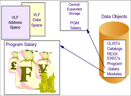
Figure 4-38 Virtual lookaside facility
Virtual lookaside facility
VLF is a z/OS component that improves the response time of applications that must retrieve a set of objects (data or code for many users). VLF creates and manages a data space to store an application's most frequently used objects. When the application makes a request for an object, VLF checks its data space to see if it is there. If the object is present, VLF can rapidly retrieve it without requesting I/O to DASD.
To take advantage of VLF, an application must identify the objects that it needs. Objects should be small to moderate in size, named according to the VLF naming convention, and associated with an installation-defined class of objects.
z/OS components and products, such as LLA (load modules), TSO/E (Restructured Extended Executor (REXX) and command list (CLIST) procedures), control address space (CAS, for user catalog entries), and RACF (RACF database entries), use VLF as an alternate way to access their objects. Because VLF uses virtual storage for its data spaces, there are main storage performance considerations that each installation must weigh when planning for VLF.
|
Important: VLF is intended for use with major applications. Because VLF runs as a started task that the operator can stop or cancel, it cannot take the place of any existing means of accessing data on DASD.
Any application that uses VLF must also be able to run without it.
|
4.38 Memory hierarchy
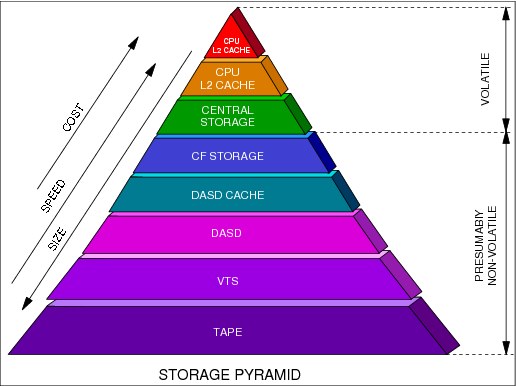
Figure 4-39 Memory hierarchy
Memory hierarchy
The memory hierarchy shown in Figure 4-39 illustrates the different layers of memory along a computational process. The higher the layer of memory, then the faster, more expensive, and smaller it is. The top layers are directly accessed by the processor.
The problem is how to distribute data and programs across memory, with regard to their importance to the business and their frequency of use. There are several considerations to remember:
•Which data (and programs) need to migrate to a lower layer when the occupied layer is full or close to full? In this case there are two algorithms that can be used:
– A least recently used (LRU) algorithm keeps the most referenced data or programs in storage. This assumes, for commercial processing, that if data or code was referenced in the past, it will likely be referenced in the future, as well. LRU is good for random access, such as in an online environment.
– A sequential algorithm is used for sequential access. After data is accessed in a high layer (such as main storage), it can be demoted to the DASD cache because there are no chances for a revisit.
•What do you do with data that was updated in a volatile layer? In this case, there are also two algorithms that can be used:
– Store-in, where the updated data is kept in the volatile layer (main storage, for example) without being copied to the non-volatile lower layer (the DASD cache, for example). This algorithm favors performance but demands a log to keep write integrity. Examples of store-in include the L2 cache and the DB2 buffer pool in virtual storage (main storage).
– Store-through, where the updated data is immediately (synchronously) copied to the volatile lower layer (generally demanding an I/O operation to the DASD cache). This algorithm favors write integrity, but does not help performance. Examples of store-through include the L1 cache and the VSAM buffer pool in virtual storage
(main storage).
(main storage).
•How can integrity problems be solved when the lower layers are shared between different copies of z/OS systems? Such data sharing helps continuous availability (24x7), but a coupling facility (CF) is needed.
..................Content has been hidden....................
You can't read the all page of ebook, please click here login for view all page.