<ENTERPRISE NAME>
<PLACE LOGO HERE>
<author><version><revision date>
This is a template for the Service Integration Architecture Specification. This page should be removed prior to publication of the specification. The template is a guide for the enterprise and should not be blindly followed. The organization should
Review the chapter in the book that refers to the template to understand its use.
Examine the template outline and determine what additions might be necessary based on unique organizational needs.
If absolutely necessary, remove any sections that will not apply. (The authors strongly discourage this practice.)
Save the template for future use.
Begin to develop the document.
Guidance is given for preparation of the document throughout the template.
Text shown as normal text should be used in the document. It may be modified as necessary.
Text shown in pointed brackets is either instructional guidance in the application of the document or a description of the type of information to be added and should be removed prior to publication.
Text shown in double-pointed brackets is a placeholder for the insertion of text by the authors.
Headers and footers should be customized as necessary as a final step in the completion of the document.
Service Integration Architecture Specification
This specification provides architecture and design guidance for applying a service-oriented architecture approach to integration for <<system name>>. This document will be the design and architecture specification for the development of the application.
<The scope of this specification is limited to an application or system. The document should define the architecture and design for applying a service-oriented architecture approach. The scope should describe the scope of the application or system that is defined in the architecture and design.>
<This section should define the users of the application or system, the development team who will execute the implementation of the design, and the team responsible for the architecture and design. Any other participants or stakeholders should also be identified including their roles.>
<Business Events define the business activities that the system must support. A business event
Occurs in the business environment
Occurs at a given point in time
Must be responded to by the system
The Event Table describes the relevant activities that happen in the business and the required system responses. There are two types of events: business events and temporal events. Business events are activities that occur in the business. Business events are detected by defining each business activity within the scope of the system. Temporal events occur at a predetermined point in time. Temporal events exist because the business policy demands that certain system activities occur at certain times, or because the system produces its outputs on a timed basis.
In the Event Description column, include how the event is initiated or detected. When defining Responses, give descriptive names that unambiguously define what the system response is, such as “Verify existing customer,” “Enter New Customer,” “Check Credit.”>
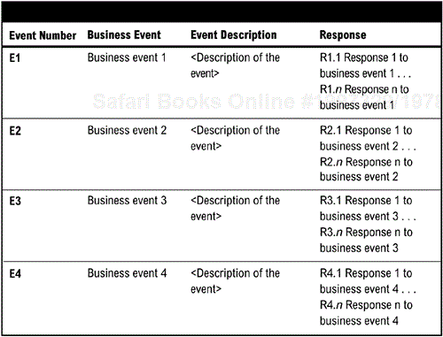
<The system responses defined in the Events Table define the essential services the system must provide. Some required functionality already exists and other functionality will be new and must be developed, then integrated. The service descriptions define the scope of functionality required to perform a specific business service.
To maximize business agility and IT investment, business services should be defined at the level of granularity that will optimize reuse. Tight cohesion—grouping closely related functions together into business services, and loose coupling between services are the design metrics that will yield more reusable design. The service description should include the methods to be supported by the service, the inputs and outputs, and the general description. This level of description is sufficient for developing a Web service or other interface. Starting from the business level definition, it drills down to a level sufficient to turn the service description into a Web service.>
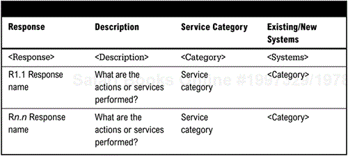
<The Service Category Table lists all required responses to business events, defines whether the function already exists in one or more systems, or if it is a new functionality. The table also defines likely services to provide the functionality. The service at this point is a first best guess at a services definition and will be refined further in the next step. When defining services, think of modules within an existing application that may perform the service or likely component modules for development.>
<Each service should be described in terms of its function and systems used to implement the function. In creating this table, group all functions and responses together that will form a cohesive module. For example, the service should manage a particular set of data, such as customer information or product information, or should perform a specific service than might be used in other applications, such as credit checking or pricing. There should be loose coupling between services. Each service should interact with any other service through the defined interface. Changes in one service should not impact functioning of other services.
The description should define how the service would be implemented. For example:
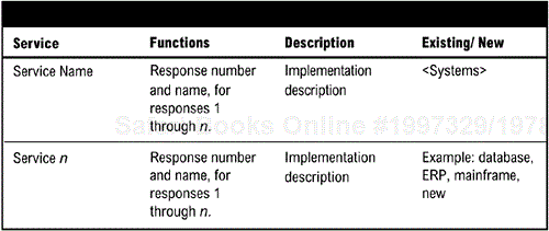
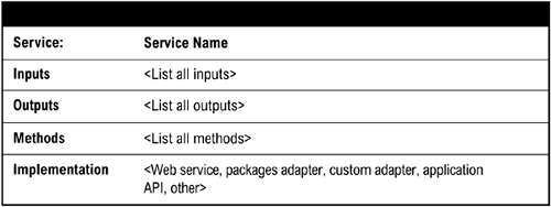
<While the Web services standard defines how to specify an interface, it does not define the data and functionality that the interface needs to contain. The Service Interface Specification provides the information necessary for creating Web services or other application or component interfaces. Using the Service Definition Table, list all inputs, outputs, and methods that the interface needs to support, and determine how the interface will be implemented.
Inputs should include all data fields and/or functions the interface must support. Likewise, the outputs should also include all data fields and/or functions the interface must support. For example, a credit check service might define inputs as customer ID, name and telephone number, and amount; and outputs as credit approval or credit disapproval.>
<Use Cases define actors and how they interact with the system services. Actors represent a role, and can be humans, other computers, pieces of hardware, or other software systems. They must supply stimuli to initiate the event that in turn requires a system response (or service). Use cases describe the behavior of the system when one of these actors sends one particular stimulus. It depicts the business events and system responses in terms of the event stimulus that triggers the use case—the inputs from and outputs to other actors, and the behaviors that convert the inputs to the outputs.>
<The basic components of use case diagrams are the actor, the use case, and the association. To create the use case, identify the primary actors in the system, then prioritize the services to be implemented. We recommend creating a use case for each proposed service.
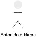
Actor | An actor is depicted using a stick figure, and the role of the user is written beneath the icon. Actors can be humans, other computers, pieces of hardware, or other software systems. |
|
Use Case | A use case is depicted with an ellipse. The name of the use case is written within the ellipse. |
|
Association | Associations are links between actors and use cases, and indicate that an actor participates in the use case in some form.> |
|
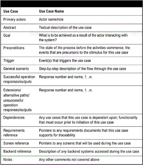
<The Use Case Specification contains text that further describes the use case. The text specification also usually describes everything that can go wrong during the course of the specified behavior, and what remedial action the system will take. This specification can be customized or expanded to handle particular issues within an implementation or organization.>
<The appendix should list any reference documents used in the creation of the document so that its contents can be traced back to their sources if necessary. This should be broken down into internal documents and external documents. Internal documents are those that belong to the organization. External documents are items such as articles, whitepapers, Web sites, or product documentation.>

