
Chapter 2
Self-controlled Synchronous Motor: Dynamic Model Including the Behavior of Damper Windings and Commutation Overlap 1
2.1. Introduction
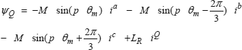
This chapter studies the same system examined in Chapter 1 – a synchronous motor supplied by a thyristor bridge operating as a current inverter and a control system that links the starting angle of the thyristors to the rotor position, as can be seen in Figure 2.1.
Figure 2.1. Principle diagram of the self-controlled synchronous machine (identical to the diagram in Figure 1.1)

The aim is to develop a macroscopic model similar to that presented in section 1.10. This will take into account the transient regime due to the damper windings, without making the hypothesis that the overlap angle (the electric angle during which the armature current is transferred from one phase to the other during the commutation) is zero. As in Chapter 1, we will assume that the synchronous machine has a cylindrical rotor, the couplings between the windings are sinusoidal, the field winding is supplied with a current source and that there is no magnetic saturation.
Since the overlap angle is not assumed to be zero, the model obtained will have at least one more degree of freedom, and thus need an additional equation to set this. It will have to remain simple enough to be used in a control system. To define the armature circuit, we will use a variable ![]() that, in association with overlap angle
that, in association with overlap angle ![]() , sets the beginning and end times of commutations, as shown in Figure 2.2, which uses some elements included in Figure 1.6.
, sets the beginning and end times of commutations, as shown in Figure 2.2, which uses some elements included in Figure 1.6.
Figure 2.2. Definition of angles ![]() and
and ![]() . Drawing done for
. Drawing done for ![]() = 182° and µ = 18°
= 182° and µ = 18°

Angle ![]() can be considered the position of the center of the fictitious brushes introduced in section 1.9, but defined with respect to the magnetic axis of the field winding. It therefore plays a role comparable to that of angle
can be considered the position of the center of the fictitious brushes introduced in section 1.9, but defined with respect to the magnetic axis of the field winding. It therefore plays a role comparable to that of angle ![]() S considered in section 1.9, that was defined with respect to the magnetic axis of phase a. The link between these two variables is:
S considered in section 1.9, that was defined with respect to the magnetic axis of phase a. The link between these two variables is:
where ![]() em is the electric position of the rotor.
em is the electric position of the rotor.
In section 1.10, neglecting overlap angle ![]() enables us to well-define the armature circuit at each moment: it consists of the anti-series connection of the two stator windings in which current flows. This circuit is completely defined for each value of rotor electric position
enables us to well-define the armature circuit at each moment: it consists of the anti-series connection of the two stator windings in which current flows. This circuit is completely defined for each value of rotor electric position ![]() em, by position
em, by position ![]() S of the fictitious brushes. This is no longer the case if we consider an overlap angle
S of the fictitious brushes. This is no longer the case if we consider an overlap angle ![]() other than zero. To extend the notion of the armature circuit, we will follow a formalism inspired by a method often used to calculate circuit type quantities at the end of a field calculation (see, for example, [DUF 97, REM 05 or MAT 02]). The armature circuit will be defined by giving three sharing coefficients Na, Nb and Nc. The currents in the three stator phases will then be defined by:
other than zero. To extend the notion of the armature circuit, we will follow a formalism inspired by a method often used to calculate circuit type quantities at the end of a field calculation (see, for example, [DUF 97, REM 05 or MAT 02]). The armature circuit will be defined by giving three sharing coefficients Na, Nb and Nc. The currents in the three stator phases will then be defined by:
[2.2] ![]()
In this formula, the upper indices have been attributed to currents ik [KRO 59, p. 101, MYL 08] and to parameters Nk. This is to remind us that they are contravariant variables [SYN 49].
We will try to express coefficients Nk as a function of ![]() em and a small number of variables considered constant at the scale of a commutation, as is the case in particular for
em and a small number of variables considered constant at the scale of a commutation, as is the case in particular for ![]() and
and ![]() . In practice, for this purpose we will choose simplified expressions of functions Nk, so that formula [2.2] will be approximate. The choice of these functions is arbitrary in a way. It results from a compromise between simplicity of the expressions used and the wish to obtain, in conditions of normal operation, evolutions of the currents close to their exact evolutions using equations [2.2].
. In practice, for this purpose we will choose simplified expressions of functions Nk, so that formula [2.2] will be approximate. The choice of these functions is arbitrary in a way. It results from a compromise between simplicity of the expressions used and the wish to obtain, in conditions of normal operation, evolutions of the currents close to their exact evolutions using equations [2.2].
2.2. Choice of the expression of Nk
In this chapter, we will choose functions Nk so that the currents ik, when computed with the approximations introduced in Chapter 1 to study commutations, can be exactly represented with the help of functions Nk. These approximations are that current I at the input of the bridge that supplies the motor (armature current) is constant (infinite inductance in series with the supply), that the resistances of the damper windings are negligible and that steady-state operation is established. These assumptions have allowed us to define commutation electromotive forces (emfs) ea, eb and ec. Using these emfs, we can define angles ![]() ,
, ![]() ,
, ![]() ,
, ![]() ,
, ![]() C and
C and ![]() , as shown in Figure 2.3, which uses some elements from Figure 1.6.
, as shown in Figure 2.3, which uses some elements from Figure 1.6.
Figure 2.3. Definition of angles ![]() ,
, ![]() ,
, ![]() ,
, ![]() and
and ![]() . Drawing done for
. Drawing done for ![]() = 182°,
= 182°, ![]() = 18° and
= 18° and ![]() = 50°
= 50°

Let us recall that, in section 1.4, the overlap angle is defined as the difference between angle α at the start of a commutation and angle ξ at the end of a commutation. These are referred to in Chapter 1 with respect to the crossing time of commutation emfs of the phases involved in the commutation process:
[2.3] ![]()
All the angles in Figure 2.3 can be defined as a function of ![]() ,
, ![]() and
and ![]() . In particular, we have:
. In particular, we have:
[2.4] ![]()
With equation [2.3], from equation [2.4] we get:
Furthermore, similarly to [1.24], we can write:
[2.6] ![]()
In accordance with what is indicated in section 1.4, the commutation of current I from phase c to a at the + input terminal takes place during the interval defined by:
[2.7] ![]()
where ![]() em is the rotor electric position angle, which is equal to p
em is the rotor electric position angle, which is equal to p ![]() m t for steady-state operation.
m t for steady-state operation.
During this commutation, current ia is given by formula [1.9], which becomes:
whereas equation [1.10] is written as:
By eliminating EC between these two equations, after a few simplifications we get:

The form of this equation leads us to choose:
[2.11] 
Expression [2.11] is function of ![]() in a complicated way and of
in a complicated way and of ![]() em in a very different way. We can obtain a simpler expression by replacing variable
em in a very different way. We can obtain a simpler expression by replacing variable ![]() with variable
with variable ![]() :
:
[2.12] ![]()
Equation [2.11] is then written:
[2.13a] 
During the interval defined by [2.7], all of the current I returns via phase b, so we will take:
and since current I is shared between phases c and a, for Nc we will take the complement to 1 of equation [2.13a], i.e.:

We will notice that ![]() intervenes in expressions [2.13] only by its value module 180°. Indeed, subtracting or adding a value of 180° to
intervenes in expressions [2.13] only by its value module 180°. Indeed, subtracting or adding a value of 180° to ![]() leaves the value of these expressions unchanged.
leaves the value of these expressions unchanged.
Within the framework of the new model, the signification of angle ![]() , or
, or ![]() which replaces it, must be redefined. This will be done later on. At the moment, these angles represent an additional degree of freedom that we can use.
which replaces it, must be redefined. This will be done later on. At the moment, these angles represent an additional degree of freedom that we can use.
Figure 2.4 shows the variation of Na on the interval defined by [2.7] for different values of ![]() .
.
We see that ![]() degree of freedom, which replaces
degree of freedom, which replaces ![]() via equation [2.12], does not have any influence on the limits [2.7] of the overlap interval. Via equation [2.13] it gives the evolution of way the current I is shared between the phases during the overlap interval. We will notice that the current evolution is almost linear on the interval defined by equation [2.7] when
via equation [2.12], does not have any influence on the limits [2.7] of the overlap interval. Via equation [2.13] it gives the evolution of way the current I is shared between the phases during the overlap interval. We will notice that the current evolution is almost linear on the interval defined by equation [2.7] when ![]() = 180°. In this case, in the middle of the overlap interval, we have Na = Nc = 0.5.
= 180°. In this case, in the middle of the overlap interval, we have Na = Nc = 0.5.
Figure 2.4. Drawing of Na for different values of ![]() , for
, for ![]() = 182° and
= 182° and ![]() = 40°
= 40°

The current sharing defined by equation [2.13] is not the only option. Another interesting choice would be to consider a linear commutation, or a linear variation of Na between 0 and 1 on the interval defined by equation [2.7] and Nc from 1 to 0 on the same interval. This has the advantage of not involving variable ![]() , but is a little less accurate. A quasi-linear commutation law can also be obtained by setting
, but is a little less accurate. A quasi-linear commutation law can also be obtained by setting ![]() to 180° (or 0°) in formulae [2.13].
to 180° (or 0°) in formulae [2.13].
The interval that follows the one set by equation [2.7] is defined by:
[2.14] ![]()
During this interval, we have:
[2.15a] ![]()
The union of intervals given by equations [2.7] and [2.14] forms the interval defined by:
[2.16] ![]()
This interval has a length of π/3 radians. The sharing of current I between the phases during the following intervals of π/3 is similar to that described by equations [2.13] and [2.15] to within about a permutation of indices abc and possibly a statoric electrical variables sign change. We can hence restrict the study to the interval defined by equation [2.16].
The current sharing obtained from equations [2.13] and [2.15] possesses several properties that will ease the analysis:
[2.17a] ![]()
[2.17b] ![]()
Property [2.17b] is due to the choice of variables ![]() ,
, ![]() and
and ![]() which depend on Nk. We will notice that properties [2.17] would have remained valid if we had used the hypothesis of a linear commutation.
which depend on Nk. We will notice that properties [2.17] would have remained valid if we had used the hypothesis of a linear commutation.
Another noticeable property of sharing using equations [2.13] and [2.15], which is a general property of collector machines, is that:
[2.18] ![]()
From now on, we will no longer assume that the forms of sharing coefficients Nk are known, but we will only use general properties [2.17] and [2.18]. We will refer to the analysis made in Chapter 1 to set the equations that govern the electromechanical variables ![]() ,
, ![]() and
and ![]() in section 2.6. The particular case in [2.13] and [2.15] will be developed in the appendices and used for the numerical simulations in section 2.9.
in section 2.6. The particular case in [2.13] and [2.15] will be developed in the appendices and used for the numerical simulations in section 2.9.
2.3. Expression of fluxes
When the inductances rapidly vary over time, it is interesting to take fluxes ![]() as state variables. Indeed, their time derivative can be obtained directly by using Faraday’s law:
as state variables. Indeed, their time derivative can be obtained directly by using Faraday’s law:
[2.19] ![]()
where ![]() is the flux of a given circuit branch, u its voltage and e its emf.
is the flux of a given circuit branch, u its voltage and e its emf.
The fluxes are linked to the currents by a relationship that does not involve time derivatives, so at each step we can calculate the currents as a function of fluxes.
Assuming, as indicated before, that the machine studied has sinusoidal coupling and linear materials, the fluxes of the five circuits of this machine are linked to the currents by:
[2.20a] 


[2.21a] 
where:
– LS is the self-inductance of one phase of the stator;
– MS is the mutual inductance between two phases of the stator; and
– MRf is the mutual inductance between the damper winding of the main axis and the field winding.
The other parameters, which are defined in Chapter 1, are:
– M, the maximum value of the inductance between a phase of the stator and a damper winding;
– Mf, the maximum value of the inductance between a phase of the stator and the field winding;
– LR, the self-inductance of a damper winding.
Figure 2.5 shows the model considered.
Figure 2.5. Detailed model considered (the mutual inductances between the rotor and the stator have not been shown)

Since the resistances of the rotoric circuits are small, fluxes ![]() D and
D and ![]() Q vary slowly. Currents iD and iQ, in contrast, vary quickly. It is therefore interesting to eliminate these currents in function of the corresponding fluxes in equations [2.20]. Knowing that the sum of the phase currents is zero, we thus obtain the three following equations:
Q vary slowly. Currents iD and iQ, in contrast, vary quickly. It is therefore interesting to eliminate these currents in function of the corresponding fluxes in equations [2.20]. Knowing that the sum of the phase currents is zero, we thus obtain the three following equations:
[2.22a] ![]()
where:
is the parameter already defined in equation [1.2], taking into account that [GRE 01]:
and where:
[2.25a] ![]()
Assuming that the fluxes given by equations [2.25] are constant, and hence equal to their mean value (from now on, we will refer to mean values with capital letters), by taking the time derivative of [2.22] and comparing the result obtained from equations [1.6] and Figure 1.5, EC, ![]() C and
C and ![]() may be redefined as follows:
may be redefined as follows:
and, taking into account equation [2.6]:
[2.28] ![]()
The calculation of fluxes ![]() D and
D and ![]() Q is important since they intervene, via fluxes [2.25], in expression [2.22] of the armature fluxes and, if we choose functions [2.13], in the calculations of these functions via angle
Q is important since they intervene, via fluxes [2.25], in expression [2.22] of the armature fluxes and, if we choose functions [2.13], in the calculations of these functions via angle ![]() (in equation [2.28]).
(in equation [2.28]).
By substituting equation [2.2] in expression [2.21] of fluxes ![]() D and
D and ![]() Q, we can write:
Q, we can write:
[2.29a] ![]()
where we have set:
[2.30a] ![]()
[2.30b] ![]()
By substituting equations [2.29] in [2.25], we obtain:
[2.31a] ![]()
In equations [2.29] and [2.31], X, Y, iD and iQ are the only variables that significantly vary during the interval defined by equation [2.16]. By making the approximation that the other variables are constant during this interval, we can switch to mean values, which leads:
[2.32a] ![]()
[2.33a] ![]()
To obtain an equation of the form [2.19] for the armature circuit, we need to define the flux of this circuit. We obtain this flux by taking the sum of phase fluxes [2.22] weighted by coefficients Nk. The choice of this definition of the armature flux will be justified later on by the forms of macroscopic equations that follow on from it. By again introducing equation [2.2], we thus obtain:
[2.34] ![]()
where we have defined:
[2.35] ![]()
The switch to mean values made in equation [2.34] leads to the macroscopic equation of the armature flux. We will refer to <X>, <Y> and <Z> as the mean values of coefficients X, Y and Z. By adding the smoothing inductance LDC, shown in Figure 2.5, in the armature circuit, we get:
[2.36] ![]()
Introducing LDC in equation [2.36] allows us to take into account the fact that this inductance is not infinite in the dynamic equations.
We can write the armature flux as a function of the currents by introducing [2.33] therein. We get:
[2.37] 
The expression of the field winding flux can be found without difficulty:
[2.38] ![]()
Coefficients <X>, <Y> and <Z>, present in equations [2.37], [2.38] and [2.32], depend on ![]() ,
, ![]() and
and ![]() alone. These coefficients are calculated assuming that
alone. These coefficients are calculated assuming that ![]() ,
, ![]() and
and ![]() are constant during the averaging interval defined by equation [2.16]. Their analytical expression is given in the appendix for the choice of functions Nk given by equation [2.13]. Let us notice here and now that <Z> normally takes a value close to 2. Indeed, taking into account the definition [2.35] of <Z>, equation [2.18] and assuming that |Nk| ≤ 1, we know that, during the interval defined by equation [2.16], Z varies between 2 and a minimum value of (1/2)2 + 1 + (1/2)2 = 1.5. Moreover, during this interval, except during the overlap interval which is defined by [2.14], Z keeps the constant value 2. Its mean value will therefore normally be slightly below 2.
are constant during the averaging interval defined by equation [2.16]. Their analytical expression is given in the appendix for the choice of functions Nk given by equation [2.13]. Let us notice here and now that <Z> normally takes a value close to 2. Indeed, taking into account the definition [2.35] of <Z>, equation [2.18] and assuming that |Nk| ≤ 1, we know that, during the interval defined by equation [2.16], Z varies between 2 and a minimum value of (1/2)2 + 1 + (1/2)2 = 1.5. Moreover, during this interval, except during the overlap interval which is defined by [2.14], Z keeps the constant value 2. Its mean value will therefore normally be slightly below 2.
2.4. General properties of coefficients <X>, <Y> and <Z>
Before developing the model further, it is useful to establish a few properties of the coefficients that can be found therein. We are going to establish these properties by assuming that equations [2.17] and [2.18] are fulfilled. This is more general than assuming that coefficients Nk are given by equation [2.13].
Returning to definition [2.30b], we have:
[2.39] 
The first term of equation [2.39], being the derivative of a periodic function, has a mean of 0. Hence, using equation [2.17b], we obtain:
[2.40] ![]()
namely:
[2.41a] ![]()
A similar development leads to:
A consequence of equations [2.41] is that:
[2.42] 
From equations [2.41], we can infer that <X> and <Y> are sinusoidal functions of variable ![]() , which are identical to within a phase shift of about 90°.
, which are identical to within a phase shift of about 90°.
Moreover, by using definition [2.35] we have:
[2.43] ![]()
namely, taking into account equation [2.17b]:
Since Z is a periodic function of ![]() em, the mean value of its derivative is 0. We thus obtain:
em, the mean value of its derivative is 0. We thus obtain:
[2.45] ![]()
When the overlap interval ![]() tends to 0, we can calculate:
tends to 0, we can calculate:
[2.46a] ![]()
[2.46b] ![]()
Equations [2.46a-c] fulfill the properties demonstrated in this section.
2.5. Electrical dynamic equations
Equations [2.32] and [2.37] can be used to calculate I, ID and IQ at each time. To describe the evolution of fluxes ![]() D and
D and ![]() Q, we obtain equations of the form [2.19]. Since the damper windings are in short-circuit, their voltage is 0. Their emf is purely ohmic, since they are filiform circuits. We hence obtain:
Q, we obtain equations of the form [2.19]. Since the damper windings are in short-circuit, their voltage is 0. Their emf is purely ohmic, since they are filiform circuits. We hence obtain:
To retain the formalism of equation [2.19], the evolution of ![]() must be determined by an equation of the form:
must be determined by an equation of the form:
[2.48] ![]()
where UDC is the supply voltage. E is a mean emf whose expression will be determined. The expression of the left-hand side of [2.48] is easily inferred from [2.37]. It remains to obtain an analytical expression of the voltage UDC to be able to infer that of the emf from equation [2.48].
The different armature phases are filiform circuits (according to the meaning given in [MAT 04]). We therefore obtain their voltage by taking the derivative of their flux (equation [2.22]) and adding the ohmic voltage drops. We thus have:
[2.49a] 


The armature voltage is given by the sum of these three voltages weighted by coefficients Nk. It should be noted that the value of the voltages given by equations [2.49] for the phases under commutation are not necessarily equal, as they would be if we used the exact expressions of coefficients Nk. This is not a problem with the above-mentioned way of computing the armature voltage. By using equations [2.30] and [2.35], we thus obtain the armature voltage:
[2.50] 
By switching to mean values, the first term in equation [2.50] will disappear since, Z being a periodic function of ![]() em, the mean of its derivative is 0. The second term will be canceled out by equation [2.45]. The following five terms, as well as the last one, have only one rapidly variable factor, so switching to mean values does not represent any difficulty. Even if the fluxes vary slowly, the case is not the same for their derivatives. These are linked to ohmic voltage drops RRiD and RRiQ, which have a rapidly variable part.
em, the mean of its derivative is 0. The second term will be canceled out by equation [2.45]. The following five terms, as well as the last one, have only one rapidly variable factor, so switching to mean values does not represent any difficulty. Even if the fluxes vary slowly, the case is not the same for their derivatives. These are linked to ohmic voltage drops RRiD and RRiQ, which have a rapidly variable part.
To find the expression of currents iD and iQ, we can calculate the difference between equations [2.29] and [2.32], then disregard differences ![]() D −
D − ![]() D and
D and ![]() Q −
Q − ![]() Q. We thus obtain:
Q. We thus obtain:
[2.51a] ![]()
By switching to the time derivative of the difference between equations [2.29] and [2.32], using equations [2.51] we obtain:
and, by [2.25],
[2.53a] ![]()
By substituting equation [2.53] in [2.50], then switching to mean values, by adding the armature circuit inductance LDC and resistance RDC of the smoothing inductor, we get:
[2.54] 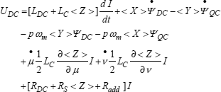
where:
which can also be written by using equation [2.18] [MAT 11]:
[2.56] ![]()
Expression [2.54] can be broken down into one term of the form d![]() /dt and one emf term. By subtracting the time derivative of flux
/dt and one emf term. By subtracting the time derivative of flux ![]() computed using [2.36] from equation [2.54], and by using general properties [2.41] and [2.43], we obtain the expression of the emf:
computed using [2.36] from equation [2.54], and by using general properties [2.41] and [2.43], we obtain the expression of the emf:
[2.57] 
Expression [2.57] does not involve any time derivative of the electrical variables, which justifies ex post facto the choice of macroscopic expressions of flux and voltage. At each step we can thus evaluate the derivatives of electromechanical variables ![]() ,
, ![]() and
and ![]() , calculate the value of E by using [2.57] and introduce it in equation [2.48] to obtain the evolution of the armature flux.
, calculate the value of E by using [2.57] and introduce it in equation [2.48] to obtain the evolution of the armature flux.
We will notice that emf (equation [2.57]) is not restricted to the ohmic term. The armature circuit is not a filiform circuit (according to the meaning given in [MAT 04]).
The first term of [2.57] is a sliding term: it cancels out if d![]() /dt = -p
/dt = -p ![]() m, i.e. when the armature circuit (the equivalent circuit in which current I is assumed to flow), does not move with respect to the stator windings. The second and third terms are non-lineic terms, which take into account variations in the form of the armature circuit. The fourth term is an ohmic term.
m, i.e. when the armature circuit (the equivalent circuit in which current I is assumed to flow), does not move with respect to the stator windings. The second and third terms are non-lineic terms, which take into account variations in the form of the armature circuit. The fourth term is an ohmic term.
2.6. Expression of electromechanical variables
The electrical equations developed in the previous sections are only useful if we add a calculation procedure of electromechanical variables to them, i.e. of angle ![]() and, with the expression of Nk introduced in section 2.2, angles
and, with the expression of Nk introduced in section 2.2, angles ![]() and
and ![]() . The macroscopic model alone does not allow us to obtain the expressions of the electromechanical variables: it is necessary to refer to a detailed model. Therefore in this section we will sometimes refer to the approximate analysis in section 2.3.
. The macroscopic model alone does not allow us to obtain the expressions of the electromechanical variables: it is necessary to refer to a detailed model. Therefore in this section we will sometimes refer to the approximate analysis in section 2.3.
In order to determine angles ![]() ,
, ![]() and
and ![]() we need to have three equation functions of these angles (or the angle defined in Figure 2.3, which amounts to the same thing taking into account the relationships that exist between the two sets of angles) at our disposal. Relation [2.28] is a first constraint on the electromechanical variables. Equation [1.10] gives an approximate value of a second constraint, which can be written as:
we need to have three equation functions of these angles (or the angle defined in Figure 2.3, which amounts to the same thing taking into account the relationships that exist between the two sets of angles) at our disposal. Relation [2.28] is a first constraint on the electromechanical variables. Equation [1.10] gives an approximate value of a second constraint, which can be written as:
[2.58] 
There is therefore only one degree of freedom left on angles ![]() ,
, ![]() and
and ![]() , which can only be set by the control system of the thyristors. This control system can only act on the turn on times of the thyristors, i.e. on angle
, which can only be set by the control system of the thyristors. This control system can only act on the turn on times of the thyristors, i.e. on angle ![]() (the firing angle of thyristor Ta1 measured with respect to the axis of the field winding). For the purpose of analysis, we will infer the value of angle
(the firing angle of thyristor Ta1 measured with respect to the axis of the field winding). For the purpose of analysis, we will infer the value of angle ![]() from the value of
from the value of ![]() , by using the value of
, by using the value of ![]() given by equation [2.28]:
given by equation [2.28]:
[2.59] ![]()
The value of ![]() is then easy to obtain by using equation [2.59], then that of
is then easy to obtain by using equation [2.59], then that of ![]() by using equation [2.3]. We can then calculate
by using equation [2.3]. We can then calculate ![]() using an expression inferred from equations [2.4] and [2.12]:
using an expression inferred from equations [2.4] and [2.12]:
and eventually ![]() by expression [2.12].
by expression [2.12].
In addition to the fact that angles ![]() ,
, ![]() and
and ![]() must be computed to determine the coefficients defined in section 2.3, they also serve to verify that the conditions of good commutation of the thyristors are fulfilled, i.e.:
must be computed to determine the coefficients defined in section 2.3, they also serve to verify that the conditions of good commutation of the thyristors are fulfilled, i.e.:
and:
constraints that must be verified with a safety margin in order to take into account the imperfections of the modeling and analysis.
We can also set the value of ![]() and calculate all the angles, including the control angle
and calculate all the angles, including the control angle ![]() of thyristors, by following a procedure that is the inverse of the one described above. However, this type of control can lead to instabilities because, when we increase the current I in order to increase the power converted, angle
of thyristors, by following a procedure that is the inverse of the one described above. However, this type of control can lead to instabilities because, when we increase the current I in order to increase the power converted, angle ![]() and hence
and hence ![]() are also going to increase. This decreases the value of the sliding emf and hence the effect of the current increase.
are also going to increase. This decreases the value of the sliding emf and hence the effect of the current increase.
Other control strategies can also be considered. For instance, we can set the value of ![]() and infer the value of
and infer the value of ![]() from it using equation [2.12]. The value of
from it using equation [2.12]. The value of ![]() is then obtained by expression [2.58], which can be re-written in the form:
is then obtained by expression [2.58], which can be re-written in the form:
namely:
The other angles are easily obtained, in particular ![]() .
.
2.7. Expression of torque
In the case of filiform circuit systems (according to the meaning given in [MAT 04]) without magnetic saturation, the electromagnetic torque is given by:
which in our case is:
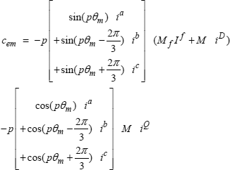
By using equation [2.2] and definition [2.30], this expression becomes:
By expressing iD and iQ as functions of ![]() DC and
DC and ![]() QC, by using [2.31], we obtain:
QC, by using [2.31], we obtain:
or, by switching to the mean value of the torque:
[2.68] ![]()
The comparison of equations [2.54] and [2.68] shows that, in steady state, the mechanical power is equal to the electrical power to roughly within the ohmic losses.
2.8. Writing of equations in terms of coenergy
By integrating equation system [2.37], [2.38] and [2.32], we obtain the expression of macroscopic coenergy:
[2.69] 
The partial derivative of [2.69] with respect to current I gives the flux (equation [2.38]). We can therefore write expression [2.40] in the form:
Let us now consider the partial derivatives of [2.69] with respect to electromechanical variables ![]() ,
, ![]() and
and ![]() . By using equation [2.33], we have:
. By using equation [2.33], we have:
[2.71] 
By using equations [2.41] and [2.45], we can infer that:
In a similar way to equation [2.71], we also obtain:
and:
We can hence write equation [2.57] in the form:
[2.73] 
Similarly, torque expression [2.68] can be written as:
[2.74] ![]()
The derivatives of wcm with respect to variables ![]() and
and ![]() do not appear in equation [2.74], and in equation [2.73] they are not multiplied by rotational speed
do not appear in equation [2.74], and in equation [2.73] they are not multiplied by rotational speed ![]() m. According to the terminology introduced by Garrido [MAT 04], variables
m. According to the terminology introduced by Garrido [MAT 04], variables ![]() and
and ![]() are non-lineic.
are non-lineic.
2.9. Application to control
For a determination of angles ![]() ,
, ![]() and
and ![]() in real time, some variables involved in their computation are not measurable, in particular those relating to the damper windings. It is therefore necessary to estimate these variables, which can be done using the equations in this chapter. Figure 2.6 shows the main steps of this calculation in the case where, further to a measure of the rotor position, we have a measure of the armature current. Considering
in real time, some variables involved in their computation are not measurable, in particular those relating to the damper windings. It is therefore necessary to estimate these variables, which can be done using the equations in this chapter. Figure 2.6 shows the main steps of this calculation in the case where, further to a measure of the rotor position, we have a measure of the armature current. Considering ![]() D and
D and ![]() Q as state variables, knowing their value at one time (the preceding time) we can calculate their derivatives and hence estimate their value at the following time (the present time). Figure 2.6 also shows how to calculate the electromechanical variables and update the values of coefficients <X>, <Y>…
Q as state variables, knowing their value at one time (the preceding time) we can calculate their derivatives and hence estimate their value at the following time (the present time). Figure 2.6 also shows how to calculate the electromechanical variables and update the values of coefficients <X>, <Y>…
Figure 2.6. Analysis of variables and coefficients at a given time, where we have a measure of the armature current

We can improve the precision of the algorithm by using a predictor-corrector method. For this purpose, the calculation of d![]() D/dt and d
D/dt and d![]() Q/dt is repeated using as values of ID and IQ the mean of their intial and final values at the step considered.
Q/dt is repeated using as values of ID and IQ the mean of their intial and final values at the step considered.
In the absence of a current sensor in the armature circuit, we can modify the Figure 2.6 to include an estimation of this current, which leads to the diagram given in Figure 2.7. The time derivatives of ![]() ,
, ![]() and
and ![]() must be estimated in order to use equation [2.57]. This is done by calculating the difference between the final and initial values of these variables at the step considered. The supply voltage is imposed and the rotational speed is measured.
must be estimated in order to use equation [2.57]. This is done by calculating the difference between the final and initial values of these variables at the step considered. The supply voltage is imposed and the rotational speed is measured.
Figure 2.7. Analysis of the variables and coefficients at a given time where we do not use a measure of armature current

We have applied the diagram in Figure 2.7 to the simulation of the transient operation following an abrupt variation of the supply voltage, by calculating the rotational speed from torque [2.68]. The program used is available on http://perso.uclouvain.be/ernest.matagne/glissant/index.htm [MAT 11]. The data relating to the system are inspired from the literature [KAT 81] relating to a motor of 2.2 kW, four poles, 200 V, 8.0 A, 50 Hz but assuming a symmetry of the direct and quadrature axes (the initial reference is about a salient pole motor). We have decreased the resistance of the damper windings to take account of damping due to the field winding, which is not considered here or in Chapter 1 since the field winding is assumed therein to be supplied by a current source. The electrical parameters chosen for the simulation are:

The mechanical parameters, inertia, viscous friction coefficient and constant antagonist torque, have a respective values of:
![]()
The voltage jump is calculated in order to switch from a speed of 1,146 rpm to a speed of 1,590 rpm.
A first simulation is done for an angle ![]() initially corresponding to 49.5°. The values of the other variables for the initial working conditions are:
initially corresponding to 49.5°. The values of the other variables for the initial working conditions are: ![]() = 6.10°,
= 6.10°, ![]() = 212° and I = 5 A. The supply voltage goes from Udc = 110 V to Udc = 153.5 Vat the initial time.
= 212° and I = 5 A. The supply voltage goes from Udc = 110 V to Udc = 153.5 Vat the initial time.
Figure 2.8 shows the evolution of the main variables during the transient interval.
The evolution of variables described in Figure 2.8 is close to the experimental reading carried out in the same conditions [KAT 81].
Figure 2.8. Evolution of main variables after an abrupt variation in voltage U at ![]() ref = 212°. We have considered that 1 p.u. of speed = 1,500 rpm, and 1 p.u. of voltage = 163.3 V
ref = 212°. We have considered that 1 p.u. of speed = 1,500 rpm, and 1 p.u. of voltage = 163.3 V

By imposing a smaller value of ![]() , we can improve the efficiency of the system: the initial value of the armature current is smaller and hence the Joule losses in the armature and the smoothing inductor are also smaller. Unfortunately, we quickly reach a situation where angle
, we can improve the efficiency of the system: the initial value of the armature current is smaller and hence the Joule losses in the armature and the smoothing inductor are also smaller. Unfortunately, we quickly reach a situation where angle ![]() cancels out during the transient phase, which makes it impossible to turn off the thyristors. We can, however, decrease angle
cancels out during the transient phase, which makes it impossible to turn off the thyristors. We can, however, decrease angle ![]() provided that we change the calculation mode of the angles when
provided that we change the calculation mode of the angles when ![]() takes a value that is too small. The simulation represented in Figure 2.9 uses this possibility, by setting the value of
takes a value that is too small. The simulation represented in Figure 2.9 uses this possibility, by setting the value of ![]() to 10° when it tends to go below this value. In this simulation, the initial and final speeds are the same as previously. The reference value of
to 10° when it tends to go below this value. In this simulation, the initial and final speeds are the same as previously. The reference value of ![]() is decreased to 201.3°, which corresponds to an initial angle
is decreased to 201.3°, which corresponds to an initial angle ![]() of 40°. The supply voltage undergoes an abrupt jump from 136.2 V to 189.7 V. The initial current is decreased to 3.91 A.
of 40°. The supply voltage undergoes an abrupt jump from 136.2 V to 189.7 V. The initial current is decreased to 3.91 A.
Figure 2.9. Evolution during an abrupt variation of voltage U at ![]() ref = 201.3°. We have considered that 1 p.u. of speed = 1,500 rpm, and 1 p.u. of voltage = 163.3 V
ref = 201.3°. We have considered that 1 p.u. of speed = 1,500 rpm, and 1 p.u. of voltage = 163.3 V

As we can see in Figure 2.9, the armature current tends towards a smaller value, which decreases the Joule heating losses.
2.10. Conclusion
In this chapter, we have extended the study of the functioning of the self-controlled synchronous machine from Chapter 1 to take into account the influence of the overlap angle. For this purpose we have applied a general method of definition of circuits to the definition of the armature circuit. This method has led to a dynamic model that takes into account the behavior of the damper windings.
The model obtained has three electromechanical variables. The first, ![]() , is a sliding variable defining the position of the armature circuit (which can be represented by the position of the fictitious brushes). The following two,
, is a sliding variable defining the position of the armature circuit (which can be represented by the position of the fictitious brushes). The following two, ![]() and
and ![]() , are non-lineic variables according to the meaning of the sliding circuit theory developed by Garrido. Variable
, are non-lineic variables according to the meaning of the sliding circuit theory developed by Garrido. Variable ![]() can be represented as the width of the fictitious brushes, whereas variable
can be represented as the width of the fictitious brushes, whereas variable ![]() describes the current form during overlap intervals.
describes the current form during overlap intervals.
We have presented the theory in the form where the flux of the armature circuit and the fluxes of the damper windings are electrical state variables. This model is sufficiently simple to be used within the framework of control and regulation systems. Finally, we have shown that this model can be put in a Lagrangian form, which opens the way to taking account of magnetic saturation.
2.11. Appendix 1: value of coefficients <X>, <Y> and <Z>
In this and the following appendices, we give exact expressions of coefficients <X>, <Y> and <Z> and their derivatives with respect to ![]() and
and ![]() for the choice of Nk (in equations [2.13] and [2.15]). If the available means of calculation are not sufficient, it is possible to use simplified versions of these expressions, for instance by setting the value of variable
for the choice of Nk (in equations [2.13] and [2.15]). If the available means of calculation are not sufficient, it is possible to use simplified versions of these expressions, for instance by setting the value of variable ![]() to 180°.
to 180°.
After a few tedious but easy calculations [MAT 11], for the coefficients corresponding to the choices of functions Nk given in equations [2.13] and [2.15], we obtain the following expressions:
[2.75] ![]()
[2.76] ![]()
and:

From [2.75] and [2.76], we can calculate:
[2.78] 
2.12. Appendix 2: derivatives of coefficients <X>, <Y> and <Z>
In addition to their derivatives with respect to ![]() given by equations [2.41], [2.42] and [2.46], from the expressions in Appendix 1 we can obtain:
given by equations [2.41], [2.42] and [2.46], from the expressions in Appendix 1 we can obtain:


2.13. Appendix 3: simplifications for small 
When the overlap interval ![]() is small, the expressions in Appendix 1, limited to the first order, are exactly [2.46a] and [2.46b], as well as:
is small, the expressions in Appendix 1, limited to the first order, are exactly [2.46a] and [2.46b], as well as:
[2.85] ![]()
The mutual inductance between the armature and the field winding, as it comes out of equations [2.37] and [2.38], amounts to:
which is in accordance with the value of <MAf> obtained in section 1.9 if we consider the correspondence between the various angles given by equation [2.4] when ![]() = 0.
= 0.
For a small ![]() , expression [2.78] at the first order becomes:
, expression [2.78] at the first order becomes:
[2.87] ![]()
Using equations [2.85] and [2.87], expression [2.56] of Radd becomes:

2.14. Appendix 4 – List of the main symbols used in Chapters 1 and 2
2.15. Bibliography
The short bibliography below complements the one in Chapter 1, to which this chapter often refers.
[DUF 97] DUFOUR S., Calcul numérique des paramètres externes de la machine à reluctance variable, PhD thesis of INPL, Nancy, 9 January 1997.
[GRE 01] GRENIER D., LABRIQUE F., BUYSE H., MATAGNE E., Electromécanique, Convertisseurs d’Énergie et Actionneurs, Dunod, Paris, France, 2001.
[KAT 81] KATAOKA T., NISHIKATA S., “Transient performance analysis of self-controlled synchronous motors”, IEEE Transactions on Industry Applications, vol. 1A, no. 2, pp. 152-159, 1981.
[KRO 59] KRON G., Tensorfor Circuits (Second Edition), Dover, New York, USA, 1959.
[MAT 02] MATAGNE E., “Physique interne des convertisseur électromécaniques”, http://perso.uclouvain.be/ernest.matagne/ELEC2311/INDEX.HTM
[MAT 04] MATAGNE E., GARRIDO M., “Conversion électronique d'énergie: du phénomène physique à la modélisation dynamique en modélisation des machines électriques en vue de leur commande”, LOUIS J-P (ed.), Modélisation des machines électriques en vue de leur commande : concepts généraux, Traité EGEM, Editions Hermès-Lavoisier, Paris, France, 2004.
[MAT 11] MATAGNE E., Supplement to this chapter, in: “Compléments à ce chapitre”, http://perso.uclouvain.be/ernest.matagne/GLISSANT/INDEX.HTM.
[MYL 08] MYLNIKOV A., “Tensor-geometric methods for problems of the circuit theory”, Journal of Mathematical Sciences, vol. 148, no. 2, pp. 192-258, 2008.
[REM 05] REMY GH., TOUNZI A., BARRE P.J., PIRIOU F., HAUTHIER J.P., “Finite-element analysis of non-sinusoidal electromotive force in a permanent magnet linear synchronous motor”, The 5th International Symposium on Linear Drives for Industry Application, LDIA 2005, Awaji Yumebutai, Hyogo, Japan, September 25-28, 2005.
[SYN 49] SYNGE J.L., SCHILD A., Tensor Calculus, University of Toronto Press, Toronto, Canada, 1949.
1 Chapter written by Ernest MATAGNE.