Chapter 15
Cybersecurity Engineering
Chapter Objectives
After reading this chapter and completing the exercises, you will be able to do the following:
 Understand basic systems engineering concepts
- Understand how to integrate systems engineering into cybersecurity
- Utilize engineering tools in cybersecurity
- Explain the use of standards in cybersecurity engineering
Introduction
The field of cybersecurity is growing rapidly. While this rapid expansion has been beneficial for the career prospects of cybersecurity practitioners, it has presented challenges for defining the profession, including the roles and requirements within cybersecurity. It is not even clear where cybersecurity belongs in a university. A wide range of approaches are used in cybersecurity and cybersecurity education. In some cases, cybersecurity is taught and practiced as a business management discipline, with a focus on policies and procedures. In other instances, it is approached as a computer science subdiscipline. This disparity in even defining cybersecurity is a significant problem for both practitioners and academia.
One result of this lack of a coherent definition of cybersecurity is the wide range of technical backgrounds and skillsets for practitioners. There are cybersecurity professionals with a strong background in computer science or engineering, and others with virtually no technical background at all. This ambiguity leads to difficulty in even defining what cybersecurity is. Some people approach it as a management issue, primarily focused on the formulation and implementation of appropriate security standards and policies. In this approach, technical skills are a secondary (or even tertiary) concern and only relevant to the implementation of security standards and policies.
A different approach to cybersecurity is to view it as a highly technical discipline. In this view, policies and procedures are still a part of cybersecurity, but they are ancillary to technical skills. This approach focuses on the technical aspects of cybersecurity, and the technical skillset of practitioners. In this view, cybersecurity practitioners are likely to have a strong computer science background, perhaps including a degree in computer science or a related discipline. This chapter embraces the technical viewpoint of cybersecurity but provides more specificity and refinement to that definition. The approach outlined in this chapter is to view cybersecurity as an engineering discipline—in fact, as a subdiscipline of systems engineering.
Defining Cybersecurity Engineering
In order to define cybersecurity engineering as a discipline, it is first necessary to define engineering. The Accreditation Board for Engineering and Technology defines engineering as follows:1
1. http://users.ece.utexas.edu/~holmes/Teaching/EE302/Slides/UnitOne/tsld002.htm
The profession in which a knowledge of the mathematical and natural sciences gained by study, experience, and practice is applied with judgment to develop ways to utilize, economically, the materials and forces of nature for the benefit of mankind.
This definition indicates that any engineering discipline must be predicated on knowledge of mathematical and natural sciences. If you consider traditional engineering disciplines (aerospace, electrical, mechanical, and so on), you realize that engineering is heavily focused on planning and testing. One must plan everything from requirements gathering to testing and rollout. Modeling is also a central concept. These are things not often done in cybersecurity.
Traditional engineering disciplines include mechanical, electrical, civil, and chemical. In the twentieth century, that list was expanded to include aerospace, bio, nuclear, computer, and other types of engineering. In the past 50 years we have seen a rise in the field of systems engineering. What all these diverse fields of engineering have in common is that they all are predicated on the same engineering principles, including rigorous design, based on application of mathematics and natural sciences. Engineering is primarily concerned with a mathematical and scientific approach to design. That systematic approach to design carries on into development and testing—and, in fact, throughout the systems life cycle. Even the rigorous design is in turn predicated on a scientific and methodical approach to requirements engineering.
Based on an understanding of engineering definitions and principles, it should be clear that in order to make cybersecurity engineering a true engineering discipline, there are elements of the practice and teaching of cybersecurity that must be changed. The most efficient way to effect such changes is to model cybersecurity engineering after some existing engineering discipline. It might seem appropriate to choose computer engineering or software engineering as templates for cybersecurity engineering; however, cybersecurity engineering inherently involves a symbiosis of a wide range of systems. Cybersecurity is not limited to computers. It also includes human factors, policies, and legal issues that are foreign to computer engineering and software engineering.
Cybersecurity and Systems Engineering
Cybersecurity inherently involves diverse computer systems, human processes, varying operating systems, and other systems involved in cybersecurity. Cybersecurity could appropriately be labeled a system of systems; therefore, systems engineering is the appropriate template for cybersecurity engineering. One of the proposals in this chapter is that cybersecurity be formalized as a subdiscipline of systems engineering.
Before cybersecurity engineering can be defined as a subdiscipline of systems engineering, it is critical to first establish a clear understanding of what systems engineering is. The International Council on Systems Engineering (INCOSE) defines systems engineering as follows:2
2.. https://www.incose.org/docs/default-source/TWG-Documents/09_iw14-se-summit_lacntydpw.pdf?sfvrsn=80cc82c6_0
Systems Engineering is an interdisciplinary approach and means to enable the realization of successful systems. It focuses on defining customer needs and required functionality early in the development cycle, documenting requirements, then proceeding with design synthesis and system validation while considering the complete problem: Operations, Performance, Test, Manufacturing, Cost & Schedule, Training & Support, Disposal.
Systems engineering is, by definition, an interdisciplinary engineering discipline. It brings together diverse fields of engineering and includes project management activities. Systems engineering is concerned with a given system, or system of systems, throughout the system life cycle. This begins with the concept phase and continues through system disposal. This is an appropriate approach for cybersecurity engineering as well.
The first area to consider is requirements engineering, which involves defining the requirements for the system to be developed. The process begins with an informal and often vague articulation of requirements as per the stakeholders and moves on to processing that information into specific and actionable system requirements. In cybersecurity, requirements engineering is a critical component that is often overlooked. Many cybersecurity projects are done simply because they meet minimum requirements for some regulatory requirement or because they are common cybersecurity tasks. Formalized requirements engineering is not a common occurrence in cybersecurity. This indicates that one benefit of formally defining cybersecurity engineering is that requirements engineering can then be integrated into cybersecurity projects.
Applying Engineering to Cybersecurity
While the engineering processes apply to all aspects of cybersecurity, it can be beneficial to consider a specific example to illustrate the application of requirements engineering. For that purpose, one can consider a penetration test. Currently penetration testing is often done in an ad hoc manner. In penetration testing, the requirements engineering process can be used to define the specific requirements for a particular penetration test. Clients often have only vague ideas about what a penetration test is and about what they want to accomplish with pen testing.
According to IEEE 830-1993, requirement is defined as:
A condition or capability needed by a user to solve a problem or achieve an objective.
A condition or a capability that must be met or possessed by a system…to satisfy a contract, standard, specification, or other formally imposed document.
Every cybersecurity project should begin by defining the requirements. For a requirement to be effective, there are several criteria the requirement must meet. There is a helpful acronym to help you understand and remember those criteria, SMART:
Specific
Measurable
Achievable
Realistic
Timely
This SMART acronym is meant to assist you in understanding what makes a good requirement. A requirement must first and foremost be specific. Stating “I want to be more secure” is too vague. Stating “I want to reduce virus outbreaks by 23% in the next fiscal year” is quite specific. If you cannot measure it in some way, how will you know if you have achieved it or if you have missed the mark? Measurability goes hand in hand with specificity. A requirement must also be achievable. Stating “I want to never have a security incident again” is simply unrealistic and unachievable. While realistic and achievable overlap, they are not exactly the same thing. For example, stating “I want to reduce virus incidents by 15%” is achievable. Stating that you want to accomplish this goal by end of business tomorrow is simply not realistic. It must also be timely, meaning that the requirement will/can be achieved in an appropriate timeline.
Requirements engineering activities begin with requirements elicitation. This is a process wherein stakeholders and engineers meet to discuss requirements. As the name suggests, the engineers elicit requirements from the stakeholders. The requirements initially gathered are then analyzed. During the requirements analysis phase UML diagrams, SysML diagrams (which we will explore later in this chapter), user stories, and other techniques may be used to clarify the requirements. Often requirements analysis is then followed with system modeling. Modeling can be done with UML or SysML modeling, or tools such as MATLAB. The idea is to explore the requirements that have been gathered. Next the requirements are specified and validated.
In requirements engineering, the systems engineer uses techniques to elicit requirements from the client or other stakeholders. This is a process that can be readily tailored to cybersecurity engineering. As one example, this can be applied to penetration testing, a subset of cybersecurity. For penetration testing, requirements engineering can involve several techniques:
- Review past incidents the client organization has had and incidents that have occurred in the same industry. Extrapolate from those specific requirements and seek the client’s agreement on those requirements.
- Use-case diagrams are common in systems engineering. They provide a very easy to understand model that even a very nontechnical stakeholder can understand. Penetration testers can use misuse cases to model potential misuses of the client’s systems. These misuse cases can include insider threats, external attackers, and even accidental security violations. Misuse cases are described in detail later in this chapter, in the section “SecML.”
- Review specific requirements from relevant regulatory bodies and industry standards. Many standards, such as the Payment Card Industry Data Security Standard (PCI DSS), define specific penetration testing requirements.
Once requirements have been gathered and approved by the stakeholder, those requirements should form the foundation of the penetration test. In systems engineering a bidirectional requirements matrix is a common tool for tracing requirements. For penetration testing, this will trace every requirement to at least one specific test that was conducted, and every single test should trace back to a specific requirement. This ensures that all requirements were met in the penetration test, and that all tests conducted were necessitated by one or more specific requirements. Figure 15.1 displays a simplified requirements matrix for a penetration test.

Figure 15.1 Requirements bidirectional traceability matrix.
Clearly, an actual penetration test would have many more activities and requirements. But this figure demonstrates the usefulness of the requirements bidirectional traceability matrix when applied to penetration testing. The primary issue in this example is to integrate requirements engineering into the penetration test. The specific requirements will vary depending on the specific needs for that particular penetration test. The current issue is that existing cybersecurity curriculums do not include any systems engineering. Thus it is not uncommon to find cybersecurity professionals with no formal training in requirements engineering.
Once the requirements are established, it is necessary to plan the actual penetration test. Systems engineering provides several effective tools to aid in planning. One such tool is the Work Breakdown Structure (WBS). The WBS is a diagram that takes a large process and breaks it down into smaller, manageable pieces. This is useful for ensuring all tasks have been planned. It also breaks the project into smaller tasks to facilitate both scheduling and budgeting. A simplified Work Breakdown Structure for a single server is shown in Figure 15.2.
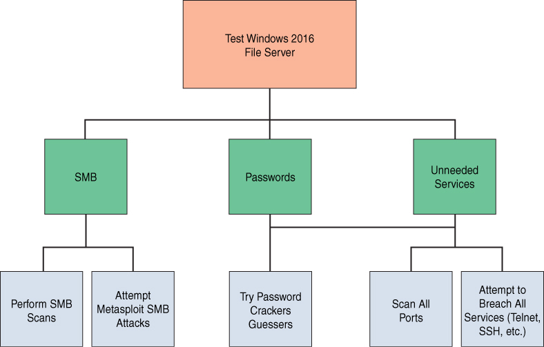
Figure 15.2 Work Breakdown Structure.
Simply by applying requirements engineering and a Work Breakdown Structure to a penetration test, one will achieve a more systematic and consistent test. This can improve efficacy of penetration testing as well as streamline efficiency. This cannot be accomplished, however, if the penetration tester is not educated on these fundamental concepts from systems engineering.
Beyond the particular example of planning and executing a penetration test is the broader issue of designing any security system. Such design principles apply to any security implementation such as deploying a new intrusion detection system (IDS), implementing new network policies, or developing a honey pot (decoy system). The current trend in cybersecurity is to perform tasks with minimal (if any) planning. This is another area where systems engineering can enhance cybersecurity.
As was previously discussed, elements from reliability engineering can also be applied to cybersecurity engineering. By integrating the established methodologies for measuring reliability, cybersecurity engineering has a ready-made set of metrics. At its core, reliability engineering is about risk management. And that is also the ultimate goal of cybersecurity.
Any integration of systems engineering with cybersecurity will have to be based on specific standards. The IEEE 15288 standard defines the system development life cycle. This same life cycle should be applied to developing security in any environment. Thus, when implementing a new intrusion detection system, or in implementing new network policies, one should follow the IEEE 15288 system development life cycle, which includes the following clauses:
- Clause 6.4.1—Stakeholder Requirements Definition Process
- Clause 6.4.2—Requirements Analysis Process
- Clause 6.4.3—Architectural Design Process
- Clause 6.4.4—Implementation Process
- Clause 6.4.5—Integration Process
- Clause 6.4.6—Verification Process
- Clause 6.4.7—Transition Process
- Clause 6.4.8—Validation Process
- Clause 6.4.9—Operation Process
- Clause 6.4.10—Maintenance Process
- Clause 6.4.11—Disposal Process
IEEE 15288 defines the process for developing or acquiring any system, beginning with defining requirements. This process is commonly taught in introductory systems engineering courses but might be foreign to many cybersecurity practitioners. Understanding the system development life cycle is essential to development of any system, including cybersecurity systems.
Any cybersecurity system must begin with the requirements engineering process. One of the hallmarks of requirements engineering is requirements elicitation. This is a process whereby the engineer elicits requirements from stakeholders. The idea is that the stakeholders may not be aware of what can be done or what should be done. The engineer’s expertise is needed to elicit a set of requirements. This is particularly applicable to cybersecurity. It is very likely that the stakeholders are not well versed in cybersecurity and will not effectively arrive at a complete list of requirements, without some assistance from an engineer.
Another tool from systems engineering that can be of significant benefit in cybersecurity engineering is the use-case diagram. This was originally part of UML and is now incorporated into SysML. The use-case diagram shows a range of users, including other systems, and how they will interact with the system of interest. The details of the use case are expounded upon later in this chapter, in the section “SecML.” However, the simple concept of modeling how users interact with a system can be very useful in defining system functionality. It is also an effective tool for communicating with stakeholders during requirements elicitation.
Unified Modeling Language (UML) is a set of diagrams used to model software. These diagrams include use-case diagrams that show how the software will be used. UML also includes deployment diagrams describing how the software should be deployed. There are a total of 14 different UML diagrams. SysML (or Systems Modeling Language) is similar but applies to any system. There are 9 different SysML diagrams.
The tools discussed in this section are just a few of the techniques that systems engineering uses that can be effectively applied to cybersecurity in general and penetration testing in particular. It can be advantageous for any penetration tester to take a course in systems engineering. Educational institutions may wish to consider adding a systems engineering course to any existing cybersecurity curriculum. At a minimum, a cybersecurity engineer should at least become familiar with the INCOSE handbook.
The tools presented in this section are only a sample of the tools utilized in systems engineering. As important as the tools are the concepts of systems engineering. For example, system modeling and simulation is common in systems engineering, but not commonly done in cybersecurity. Defining cybersecurity engineering as a subdiscipline of systems engineering requires that modeling and simulation be included.
Modeling and simulation provide a useful mechanism for testing systems in a variety of scenarios. For example, if one is developing a system to counter denial of service (DoS) attacks, then it would be useful to simulate a DoS attack to determine how the system will respond. MATLAB is already widely used to model network traffic. It is therefore appropriate to utilize MATLAB to model network traffic-based attacks. However, this modeling is not common in cybersecurity. This is one example of the application of modeling and simulation to cybersecurity engineering.
MATLAB is a tool that is commonly used in systems engineering and in other engineering disciplines. This tool has been applied to a wide range of engineering disciplines, including aerospace engineering and bioengineering. This tool should be included in cybersecurity engineering as well. The versatility of this modeling tool makes it an effective tool in many diverse engineering disciplines.
Reliability analysis is another important component of systems engineering—and one that would be well applied to cybersecurity engineering. Reliability engineering and analysis is the process of determining how reliable a given system is. Often in cybersecurity, systems are implemented without knowledge of their reliability. Reliability engineering includes a number of techniques and formulas for determining reliability.
One hallmark of all engineering disciplines is quantifiable data. It is necessary to have objective metrics in order to make informed decisions. Reliability engineering includes a number of formulas that can assist in acquiring such metrics. Fortunately, many of these do not require advanced mathematical knowledge.
The mean squared deviation formula is relatively simple and provides insight into how any system deviates from expectations. This formula is shown in Figure 15.3.

Figure 15.3 Mean squared deviation formula.
In this formula, yi is the actual value (that is, how the system was supposed to perform), and T is the target value.
Adjusting the settings of controllable inputs allows one to alter the MSD. This is a relatively simple formula from reliability engineering that can be applied to the reliability of any cybersecurity system. This would be particularly useful in evaluating the efficacy of intrusion detection systems (IDSs) and antivirus software. The MSD formula could be coupled with modeling and simulation to fine-tune the cybersecurity system before it is put into operation.
The MSD formula naturally leads to the MPE formula. The mean percentage error (MPE) is the mean number of errors from modeling, that is, the mean error of the model versus actual values. This is critical in modeling as it can be used to evaluate the efficacy of the model itself. Figure 15.4 shows the MPE formula.

Figure 15.4 Mean percentage error formula.
In this formula, n is the number of different times for which the variable is forecast, at is the actual value of the quantity being forecast, and ft is the forecast.
In addition to useful formulas for cybersecurity engineering, reliability engineering involves concepts that are applicable to cybersecurity. For example, the concept of mean time between failures (MTBF) estimates the mean time before a component will fail. For an antivirus software solution this could be the mean time before a given file is misidentified as being a virus or not being a virus. The mean time between failures can be calculated as shown in Figure 15.5.

Figure 15.5 MTBF Formula 1.
This formula appears in some cybersecurity books (including this one) and is addressed in some certification courses. A more accurate explanation of the MTBF formula can be defined as the arithmetic mean value of the reliability function R(t), which can be expressed as the expected value of the density function f(t) of time until failure. This requires integral calculus, which is shown in Figure 15.6.

Figure 15.6 MTBF Formula 2.
Don’t panic if this is new math to you. That symbol is the definite integral. I believe integration is often covered in calculus II in many universities. Clearly the MTBF formula has a clear application to cybersecurity. Understanding when a device is expected to fail is useful information. This can first be a measure of the efficacy of a given cybersecurity device or component. It can also be useful in evaluating whether any system or subsystems failure is expected or not. Furthermore, an unexpected failure could indicate an attack. However, this also indicates the need for at least basic calculus as a part of a cybersecurity curriculum.
Another concept from reliability engineering is the mean time to repair (MTTR). That is another metric that actually is currently covered in many cybersecurity books and certification courses. Continuing with the example of an antivirus software suite, what is the mean time after a virus that is not interdicted for a system to recover from the virus infection. This data would allow the cybersecurity engineer to objectively evaluate the cybersecurity system in question.
As outlined previously, cybersecurity engineering is appropriate viewed as a subdiscipline of systems engineering. By integrating elements from other domains within systems engineering, cybersecurity can be elevated to a true engineering discipline. This requires integration of reliability engineering and requirements engineering into cybersecurity. Furthermore, cybersecurity engineering requires implementing robust and effective modeling techniques. The end result of these efforts is a formal cybersecurity engineering discipline. This engineering discipline is then well defined, and the professional requirements much clearer than the current state of the cybersecurity profession.
Standards
Every engineering discipline has specific standards. The cybersecurity industry has many standards as well; however, to truly be considered cybersecurity engineering, these standards take on a more prominent role. They must be embraced fully. A few of those standards are described in the sections that follow.
RMF
NIST SP 800-37, “Guide for Applying the Risk Management Framework,” is the guiding document for this standard. It outlines specific steps:
Categorize: Determine the criticality of the asset in terms of potential adverse impacts on the organization, mission/business functions, and the system.
Select: Select security controls starting with the appropriate baseline using the selection process from the previous step. NIST has identified 18 categories of security controls (NIST SP 800-53), as outlined in Table 15.1.
Table 15.1 NIST 800-53 Security Control Families
ID | Family | ID | Family |
AC | Access Control | MP | Media Protection |
AT | Awareness and Training | PE | Physical and Environmental Protection |
AU | Audit and Accountability | PL | Planning |
CA | Security Assessment and Authorization | PS | Personnel Security |
CM | Configuration Management | RA | Risk Assessment |
CP | Contingency Planning | SA | System and Services Acquisition |
IA | Identification and Authentication | SC | System and Communications Protection |
IR | Incident Response | SI | System and Information Integrity |
MA | Maintenance | PM | Program Management |
Implement: Implement security controls within assets using sound system security engineering practices.
Assess: Determine the effectiveness of security controls and whether they are operating as intended. Also assess whether such controls meet security requirements and goals.
Authorize: Examine the output of the security controls assessment to determine whether the risk is acceptable.
Monitor: Continuously monitor the controls that are implemented for the system and its environment of operation for possible changes, signs of attack, and so on that might affect controls, and reassess the effectiveness of the controls.
ISO 27001
ISO 27001, “Standard for Information Security Management System (ISMS),” provides a framework to assist in securing systems regardless of industry or the size of the organization. You have probably heard of or even been involved in ISO 27001 audits. The standard has 14 different domains:
- A.5: Information Security Policies: The controls in this section describe how to handle information security policies.
- A.6: Organization of Information Security: The controls in this section provide a basic framework for the implementation and operation of information security by defining the internal organization (for example, roles, responsibilities, and so on), as well as organizational aspects of information security, such as project management, use of mobile devices, and teleworking.
- A.7: Human Resources Security: The controls in this section ensure that people who are under the organization’s control are hired, trained, and managed in a secure way; it also addresses the principles of disciplinary action and terminating agreements.
- A.8: Asset Management: The controls in this section ensure that information security assets (for example, information, processing devices, storage devices, and so on) are identified, that responsibilities for their security are designated, and that people know how to handle them according to predefined classification levels.
- A.9: Access Control: The controls in this section limit access to information and information assets according to real business needs. These controls are for both physical and logical access.
- A.10: Cryptography: The controls in this section provide a basis for proper use of encryption solutions to protect the confidentiality, authenticity, and/or integrity of information.
- A.11: Physical and Environmental Security: The controls in this section prevent unauthorized access to physical areas and protect equipment and facilities from being compromised by human or natural intervention.
- A.12: Operations Security: The controls in this section ensure that the IT systems, including operating systems and software, are secure and protected against data loss. Additionally, controls in this section require the means to record events and generate evidence, periodic verification of vulnerabilities, and make precautions to prevent audit activities from affecting operations.
- A.13: Communications Security: The controls in this section protect the network infrastructure and services, as well as the information that travels through them.
- A.14: System Acquisition, Development, and Maintenance: The controls in this section ensure that information security is taken into account when purchasing new information systems or upgrading existing ones.
- A.15: Supplier Relationships: The controls in this section ensure that outsourced activities performed by suppliers and partners also use appropriate information security controls and describe how to monitor third-party security performance.
- A.16: Information Security Incident Management: The controls in this section provide a framework to ensure the proper communication and handling of security events and incidents so that they can be resolved in a timely manner; they also define how to preserve evidence, as well as how to learn from incidents to prevent their recurrence.
- A.17: Information Security Aspects of Business Continuity Management: The controls in this section ensure the continuity of information security management during disruptions and the availability of information systems.
- A.18: Compliance: The controls in this section provide a framework to prevent legal, statutory, regulatory, and contractual breaches, and they audit whether information security is implemented and is effective according to the defined policies, procedures, and requirements of the ISO 27001 standard.
ISO 27001 also lists 114 security controls. This standard is one of the most widely accepted cybersecurity standards. Integrating the requirements of this standard into your cybersecurity engineering approach will improve your systems security.
ISO 27004
The ISO 27004 standard is all about metrics. Recall the SMART acronym from earlier in this chapter and remember that all requirements must be measurable. ISO 27004 is helpful in ensuring that your security systems have measurable metrics. Specifically, ISO 27004 offers guidelines on how to determine the performance of ISO 27001. You can certainly use ISO 27004 without ISO 27001, but ISO 27004 was created to provide metrics for ISO 27001. Security metrics can provide insight into the efficacy of a security system. Metrics are central to the processes of an engineer. If you cannot measure something, it very likely is not engineering.
NIST SP 800-63B
NIST SP 800-63B, “Digital Identity Guidelines,” provides guidance for authentication. Specifically, it identifies authenticator assurance levels (that is, how reliable a given level of authenticator assurance is).
Assurance level 1 includes:
- Memorized Secret (Section 5.1.1)
- Look-Up Secret (Section 5.1.2)
- Out-of-Band Devices (Section 5.1.3)
- Single-Factor One-Time Password (OTP) Device (Section 5.1.4)
- Multi-Factor OTP Device (Section 5.1.5)
- Single-Factor Cryptographic Software (Section 5.1.6)
- Single-Factor Cryptographic Device (Section 5.1.7)
- Multi-Factor Cryptographic Software (Section 5.1.8)
- Multi-Factor Cryptographic Device (Section 5.1.9)
Assurance level 2 includes:
- When a multi-factor authenticator is used, any of the following MAY be used:
- Multi-Factor OTP Device (Section 5.1.5)
- Multi-Factor Cryptographic Software (Section 5.1.8)
- Multi-Factor Cryptographic Device (Section 5.1.9)
- When a combination of two single-factor authenticators is used, it SHALL include a Memorized Secret authenticator (Section 5.1.1) and one possession-based (i.e., “something you have”) authenticator from the following list:
- Look-Up Secret (Section 5.1.2)
- Out-of-Band Device (Section 5.1.3)
- Single-Factor OTP Device (Section 5.1.4)
- Single-Factor Cryptographic Software (Section 5.1.6)
- Single-Factor Cryptographic Device (Section 5.1.7)
Assurance level 3: AAL3 authentication SHALL occur by the use of one of a combination of authenticators satisfying the requirements in Section 4.3. Possible combinations are:
- Multi-Factor Cryptographic Device (Section 5.1.9)
- Single-Factor Cryptographic Device (Section 5.1.7) used in conjunction with Memorized Secret (Section 5.1.1)
- Multi-Factor OTP Device (software or hardware) (Section 5.1.5) used in conjunction with a Single-Factor Cryptographic Device (Section 5.1.7)
- Multi-Factor OTP Device (hardware only) (Section 5.1.5) used in conjunction with a Single-Factor Cryptographic Software (Section 5.1.6)
- Single-Factor OTP Device (hardware only) (Section 5.1.4) used in conjunction with a Multi-Factor Cryptographic Software Authenticator (Section 5.1.8)
- Single-Factor OTP Device (hardware only) (Section 5.1.4) used in conjunction with a Single-Factor Cryptographic Software Authenticator (Section 5.1.6) and a Memorized Secret (Section 5.1.1)
SecML
This section is adapted from a paper written by the book’s author. That paper first defined Security Modeling Language (SecML) as a new modeling language.
Systems engineering utilizes a number of approaches to modeling systems and subsystems. Modeling is an integral part of design and testing. In fact, there is an entire field of model-based systems engineering. One of the primary modeling methods utilized in systems engineering is Systems Modeling Language (SysML). SysML is an extension of the earlier Unified Modeling Language (UML). UML was created by the Object Management Group (OMG) in order to design software. SysML extends that to modeling a wide range of systems. SysML includes nine diagrams, some of which are taken directly from UML and others of which were created for SysML.
Software engineering also includes a number of other modeling languages. For example, there are domain-specific modeling languages, such as framework-specific modeling languages (FSMLs). FSMLs are used in object-oriented programming. There are multiple, specific modeling languages for a wide range of software engineering applications.
SysML was developed for modeling systems and systems of systems. SysML is the primary modeling tool used in systems engineering. It was originally developed as an open-source specification that extended UML. In 2001 INCOSE started the SysML initiative. Eventually INCOSE worked with the OMG to create SysML. SysML v1.0 was released in 2007. The current version of SysML is 1.5 and was introduced in 2017. It is specified in ISO Standard 19514:2017, “Information Technology: Object Management Group Systems Modeling Language (OMG SysML).” A revision to version 1.9 was released in 2019.
As has been discussed, there are specific modeling techniques and even modeling languages for particular engineering disciplines. If cybersecurity engineering is to be truly defined as a separate engineering discipline, it would also benefit from its own modeling language. This would facilitate modeling that is tailored to cybersecurity needs.
An important part of systems engineering is modeling. In fact, there is an entire subdiscipline of systems engineering concerned with modeling. The concept is to facilitate better understanding of a system at any stage in the system development life cycle. Being able to simulate and model system behavior can even be used during requirements gathering. This fact supports the need for cybersecurity engineering to include a modeling language.
It is clear the modeling is an integral part of engineering, and particularly systems engineering. It is also true that modeling has been used, in a limited fashion in some aspects of cybersecurity. These facts support the need for a cybersecurity specific modeling language.
What is being proposed in this chapter is a modification to SysML in order to facilitate modeling in security. This modeling is termed SecML and is used to model security needs. The SecML definition uses some SysML and UML diagrams and adds a few new diagrams. The concept is to provide a modeling language that is specific to cybersecurity. Software engineering uses UML and systems engineering SysML; it is only natural that cybersecurity engineering should have a modeling language specific to the domain.
SecML Concepts
The general concept for Security Modeling Language (SecML) is to provide a modeling tool that can be used to effectively model both cyber-attack scenarios and defense postures. Given that cybersecurity involves systems of systems, it is appropriate to begin with SysML as a basis and modify that modeling language to formulate SecML.
Some of the diagram types are very similar to SysML diagrams, with only slight modifications. Other diagram types were created explicitly for cybersecurity applications. Unlike in UML, the language SysML is based on, the diagrams in SecML are not divided into categories such as structural, behavioral, or interaction. However, some clearly are oriented toward behavior or structure. It might seem advantageous to divide the diagrams into attack or defense-oriented diagrams; however, this was intentionally not done. Clearly diagram types such as the misuse-case diagram are appropriate for attack modeling. Similarly, the security block diagram (SBD) could be viewed as a defense-oriented diagram type. However, other diagrams such as the security sequence diagram are appropriate for both attack and defense. Therefore, the diagrams are not divided into attack and defense categories.
Misuse-Case Diagram
The first SecML diagram, and the easiest to understand, is the misuse-case diagram (MCD). Both SysML and UML utilize use-case diagrams in order to understand how users interact with a given system. Users also include other systems that might use a given system. For security purposes, the largest concern is on how an attacker might misuse a system. Therefore, it is logical to diagram misuse cases. The essence of an attack is misusing a system. Figure 15.7 shows a typical use-case diagram.
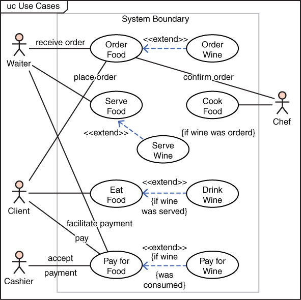
Figure 15.7 Typical use-case diagram.
In the traditional use-case diagram, some relatively simple elements are utilized. The image that appears to be a stick figure is used to represent any user of the system. This can, of course, be a human user. However, another system can in fact be a user and will still be depicted with the stick figure. Activities that are done in the system are labeled ovals. The connection between a user and a system action is represented via a line. Furthermore, when one activity extends another, that relationship is demonstrated with the dotted line and the <<extends>> label.
The UML use-case diagram has been widely used to model specific uses of a system of interest. Its utility derives from the ease of understanding it. The diagram elements are self-evident and easily understood. That is one reason why this particular UML diagram is useful in communicating with nontechnical stakeholders.
The concept of misuse cases already exists. However, the modification here is to have formal notation for the misuse. The logical starting point is the UML use-case diagram that is then modified to demonstrate misuses. This involves adding/modifying some symbolism. For the SecML misuse-case diagram, the notations shown in Figure 15.8 are added.

Figure 15.8 Misuse-case notation.
Figure 15.9 shows an exemplary use-case diagram. The diagram shows a normal user and an abuser misusing the system. It also shows which activities have some mitigation provided to address misuse and which do not yet have any mitigating factors.

Figure 15.9 Misuse-case diagram example.
The diagram can be enhanced with additional notation. For example, the indication of a countermeasure could be further described, indicating what the countermeasure is. A number is also indicated on the countermeasure symbol indicating that there are multiple countermeasures. The number of mitigating factors would be an integer inside the circle with the X, as illustrated in Figure 15.10.
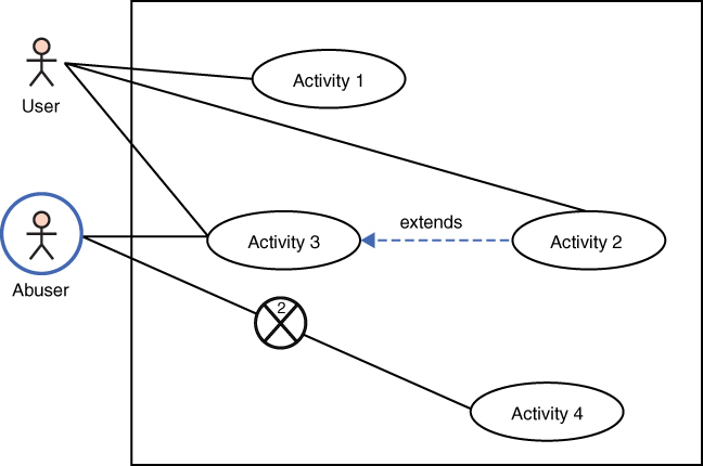
Figure 15.10 Another misuse-case example.
Figure 15.9 would then be enhanced with explanatory notes about the countermeasures employed. For example, the countermeasures could be (1) policy against downloading attachments and (2) antivirus to counter viruses sent from an abuser/attacker to a victim. The misuse-case diagram allows a cybersecurity engineer to model how the attacker would misuse the system, and what countermeasures are currently in place. More importantly, by modeling all misuse cases, it will become obvious which attack vectors have adequate mitigation measures and which do not.
Figure 15.11 provides a specific example of a misuse case. This figure shows a normal, authorized user logging in to the system. It also shows an abuser (that is, an attacker) sending an email with a malware attachment. It can be seen clearly how the abuser is misusing the normal process of sending email. It is also clear in this example that the abuser’s remote login is blocked by two mitigating factors, but there are not mitigating factors for sending email with malware attachments.
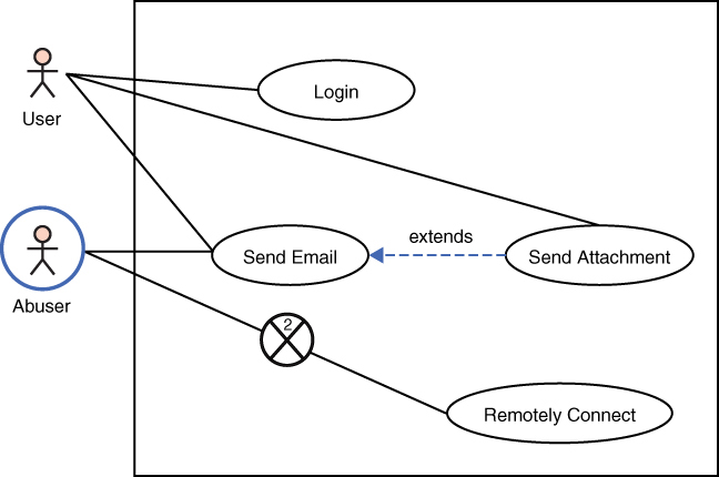
Figure 15.11 Specific misuse-case example.
Obviously, Figure 15.11 presents a rather simplified example; however, it illustrates the utility of this diagram. It immediately clarifies the attack vectors an abuser might use. Furthermore, it becomes abundantly clear that there appears to be adequate mitigation for remote connections, but not for sending malicious emails. That lack of mitigation would also facilitate phishing campaigns. The concept is that misuse-case diagrams should be created for all attack vectors to facilitate modeling and understanding of attacks, as well as selection and application of mitigating countermeasures.
Security Sequence Diagram
In SysML a sequence diagram shows how objects interact over time. Specifically, sequence diagrams show how actions are related between objects. In a security context, this is of significant importance. In any attack scenario, the sequence of data flow from one object to another is critical to the analysis. This is also applicable for defense and mitigation strategies. Understanding how an intrusion detection system interacts with security information event management (SIEM) is relevant to modeling the security of any system of interest. It would be possible to utilize the sequence diagram as it exists in SysML without any modification for security purposes.
While the sequence diagram could be used without any modification for security purposes, slight modifications would improve its utility. Thus, SecML defines a minor modification to the sequence diagram named the security sequence diagram (SSD). In SecML the sequence diagram is used in almost the same manner as it is in SysML. Figure 15.12 shows the current UML/SysML sequence diagram.

Figure 15.12 UML/SysML sequence diagram.
The sequence diagram demonstrates a sequence of actions; however, these models were meant to diagram intended activities, not attacks. To modify the sequence diagram involves adding/modifying some symbolism. For the SecML, the notation shown in Figure 15.13 is added to the security sequence diagram.

Figure 15.13 Cybersecurity addition to sequence diagrams.
Traditional sequence diagrams do not differentiate between authorized and unauthorized actions. In fact, nothing in SysML even contemplates unauthorized activities. However, in cybersecurity, unauthorized actions are of critical importance. Figure 15.14 shows an exemplary modified sequence diagram.

Figure 15.14 Modified sequence diagram.
As in a traditional SysML sequence diagram, the messages are still written with the message name above and the directionality of the message. However, the modification for SecML allows one to differentiate between normal operations and unauthorized actions. Seeing unauthorized and authorized actions as they actually occur in a system provides a very effective understanding of system operations.
The modified sequence diagram provides an overview of the sequence of events in any cyber attack. This allows the cybersecurity engineer to model various attacks. Coupling the security sequence diagram with a misuse-case diagram provides an effective overview of the attack vector in question.
Data Interface Diagram
This diagram type is created specifically for SecML. The data interface diagram (DID) is used to provide the cybersecurity engineer an understanding of data flow in the system of interest. It models the flow of data into and out of any system. The concept is to look at any system or subsystem and diagram all interfaces for data to flow into and out of the system of interest. Any place that data can flow is an area for security concerns. Data flowing outward can lead to data exfiltration. Data flowing inward can lead to malware being introduced to the system. This is shown in Figure 15.15.

Figure 15.15 Data interface diagram.
Figure 15.16 shows the specific elements of a data interface diagram.

Figure 15.16 Data interface diagram elements.
This diagram is intentionally simple. The goal is to make the process one that cybersecurity engineers can efficiently use with minimal training required. The concept is to ensure that all data flow points have been identified, and that mitigation measures have been identified. This diagram is used to examine the system of interest and to determine what, if any, mitigation strategies have been put into place for each data interface. This is essentially a limited interface diagram.
Security Block Diagram
UML, which was the basis for SysML, has a component diagram. In UML, component diagrams are used to identify components in software and to model how they connect. For example, UML contains assembly connectors that model a connection when one component requires another component. The delegation connector links an external component.
This section described the foundations of SecML, which is based on the preexisting SysML. It may be that further research leads to enhancements to these models and the addition of new models to SecML. As with all other modeling languages, it is expected that SecML will be revised and expanded.
Modeling
When considering threats, modeling is an important topic. Essentially all cybersecurity engineering is directed toward some threat. The concept of modeling is to ensure that you are building your security to counter the threats specific to your systems.
STRIDE
Threat modeling is important in any cybersecurity approaches. Microsoft created the acronym STRIDE for identifying security threats in six separate categories: spoofing, tampering, repudiation, information disclosure, denial of service, and elevation of privileges. When using this tool, it is important to ensure that you are modeling all of the enumerated threats.
PASTA
Process for Attack Simulation and Threat Analysis (PASTA) is a risk-centric seven-step methodology for evaluating risk. As the name suggests, it is about simulating attacks in order to analyze the threats. PASTA was developed in 2012. Table 15.2 lists the seven stages.
Table 15.2 Seven Stages of PASTA
Stage | Description |
Define objectives | Identify business objectives Identify security and compliance requirements Perform business impact analysis |
Define technical scope | Determine the boundaries of the technical environment Capture infrastructure dependencies |
Application decomposition | Identify use cases Define entry points and trust levels Identify threat actors Perform data flow diagramming Determine trust boundaries |
Threat analysis | Examine probabilistic attack scenarios Perform regression analysis on security events Perform threat intelligence correlation |
Vulnerability and weakness analysis | Review existing vulnerability reports Analyze design flaws and abuse cases Review scorings such as CVSS and CVE |
Attack modeling | Perform attack surface analysis Perform attack tree development Match vulnerabilities and exploits to attack trees |
Risk and impact analysis | Qualify and quantify business impact analysis Identify countermeasures Perform residual risk analysis Identify risk mitigation strategies |
DREAD
DREAD is a mnemonic for risk rating using five categories: damage potential, reproducibility, exploitability, affected users, and discoverability. How much damage would an attack cause? How easy is it for an attacker to reproduce this attack? How much effort is required to execute the attack? How many users will be impacted? Finally, how easy is it to discover the threat?
Summary
In this chapter, you have seen the application of systems engineering to cybersecurity. The goal is that you would begin to apply a methodical, systematic approach to cybersecurity. Penetration testing, as one example, should not be just a set of random hacking attempts. Rather, it should be a carefully engineered process that is mapped to specific testing requirements. It is also beneficial to model cybersecurity scenarios in order to better understand system security requirements. The SecML modeling language that was briefly introduced in this chapter provides such a methodology.
Test Your Skills
Multiple Choice Questions
1. What type of diagram is used to show how any entity might interact with a system?
A. Use-case diagram
B. Sequence diagram
C. Data interface diagram
D. Requirements diagram
2. What is the most appropriate tool for capturing the requirements of any security process or system?
A. Use-case diagram
B. Sequence diagram
C. SysML
D. Traceability matrix
3. Which of the following cybersecurity activities would be most accurately described as engineering?
A. Implementing complex IPS rules
B. Implementing asymmetric cryptography
C. Creating a requirements traceability matrix
D. Conducting a forensic investigation
4. Which modeling language is used by systems engineers?
A. SecML
B. SysML
C. UML
D. DML
5. What does this symbol represent in SecML?

A. A forbidden action
B. A blocked system
C. A countermeasure
D. An attack
6. What does this symbol represent in SecML?

A. Attack victim
B. System abuser
C. System user
D. Isolated user
7. What does this symbol represent in SecML?

A. Blocked activity
B. External attack
C. Unauthorized activity
D. Internal attack
8. What standard has 14 domains?
A. ISO 27001
B. RMF
C. NIST 800-63B
D. STRIDE
9. How many assurance levels are there in NIST 800-63B?
A. 14
B. 3
C. 4
D. 0
10. Which are the elements of STRIDE?
A. Spoofing, tampering, repudiation, information disclosure, denial of service, elevation of privileges
B. Spyware, tampering, repudiation, information disclosure, denial of service, execution
C. Spoofing, tampering, reflection attack, information disclosure, denial of service, elevation of privileges
D. Spoofing, threats, repudiation, information disclosure, denial of service, execution
Exercises
EXERCISE 15.1: Misuse-Case Diagram
Create a misuse-case diagram for a specific type of attack. You can choose any attack described in this book.
EXERCISE 15.2: Requirements Gathering
Consider the cybersecurity requirements of a college campus. Create a requirements traceability matrix for penetration testing a campus computer network.