Chapter 11
Switching and Virtual LANs
The Following CompTIA Network+ Exam Objectives Are Covered in This Chapter:
- 1.4 Explain the purpose and properties of routing and switching.
- Spanning Tree Protocol
- VLAN (802.1q)
- Port mirroring
- 2.1 Given a scenario, install and configure routers and switches.
- VLAN (trunking)
- Interface configurations
- MAC filtering
- PoE
- VTP configuration
- QoS
- Port mirroring
Layer 2 switching is the process of using the hardware addresses of devices on a LAN to segment a network. Because you’ve got the basic ideas down, I’m now going to focus on the more in-depth particulars of Layer 2 switching and how it works.
You already know that switching breaks up large collision domains into smaller ones and that a collision domain is a network segment with two or more devices sharing the same bandwidth. A hub network is a typical example of this type of technology. But because each port on a switch is actually its own collision domain, you can create a much better Ethernet LAN network by simply replacing your hubs with switches!
Switches truly have changed the way networks are designed and implemented. If a pure switched design is properly implemented, it will result in a clean, cost-effective, and resilient internetwork. In this chapter, we’ll survey and compare how networks were designed before and after switching technologies were introduced.
Routing protocols like RIP, which you learned about in Chapter 10, “Routing Protocols,” employ processes for preventing network loops from occurring at the Network layer. This is all good, but if you have redundant physical links between your switches, routing protocols won’t do a thing to stop loops from occurring at the Data Link layer. That’s exactly the reason Spanning Tree Protocol was developed—to put a stop to loops taking place within a Layer 2 switched network. The essentials of this vital protocol, as well as how it works within a switched network, are some of the important subjects that we’ll cover thoroughly in this chapter.
And to finish up this chapter, you’re going to learn exactly what a VLAN is and how VLAN memberships are used in a switched network as well as how trunking is used to send information from all VLANs across a single link. Good stuff!
To find up-to-the-minute updates for this chapter, please see www.lammle.com/forum or the book’s web site at www.sybex.com/go/netplus2e.
Networking Before Layer 2 Switching
Because knowing the history of something really helps with understanding why things are the way they are today, I’m going to go back in time a bit and talk about the condition of networks before switches and the part switches have played in the evolution of corporate LANs by helping to segment them. For a visual of how a typical network design looked before LAN switching, check out the network in Figure 11-1.
Figure 11-1: A network before switching
The design in Figure 11-1 was called a collapsed backbone because all the hosts involved had to go to the corporate backbone in order to reach any network services—both LAN and mainframe.
Going back even further, before networks like the one shown in Figure 11-1 had physical segmentation devices such as routers and hubs, there was the mainframe network. This type of network comprised mainframe controllers made by IBM, Honeywell, Sperry, DEC, and so on and dumb terminals that connected into the controller(s). Any remote sites were connected to the mainframe with bridges.
And then the PC began its rise to stardom, and the mainframe was connected to an Ethernet or Token Ring LAN where the servers were installed. These servers were usually OS/2 or LAN Manager because this was “pre-NT.” Each floor of a building ran either coax or twisted-pair wiring to the corporate backbone, which was then connected to a router. PCs ran an emulating software program that allowed them to connect to mainframe services, giving those PCs the ability to access services from the mainframe and LAN simultaneously. Eventually, the PC became robust enough to allow application developers to port applications more effectively than they ever could before—an advance that markedly reduced networking prices and enabled businesses to grow at a much faster rate.
Moving forward to when Novell rose to popularity in the late 1980s and early 1990s, OS/2 and LAN Manager servers were by and large replaced with NetWare servers. This made the Ethernet network even more popular because that’s what Novell 3.x servers used to communicate with client-server software.
So basically, that’s the story about how the network in Figure 11-1 came into being. But soon a big problem arose with this configuration. As the corporate backbone grew and grew, network services became slower and slower. A big reason for this was that at the same time this huge burst in growth was taking place, LAN services began to require even faster response times. This resulted in networks becoming totally saturated and overwhelmed. Everyone was dumping the dumb terminals used to access mainframe services in favor of those slick new PCs so they could more easily connect to the corporate backbone and network services.
And all this was taking place before the Internet’s momentous popularity, so everyone in the company needed to access the corporate network’s own, internal services. Without the Internet, all network services were internal, meaning that they were exclusive to the company network. As you can imagine, this situation created a screaming need to segment that single, humongous, and now plodding corporate network, which was connected together with sluggish old routers.
How was this issue addressed? Well, at first, Cisco responded by simply creating faster routers (no doubt about that), but still more segmentation was needed, especially on the Ethernet LANs. The invention of Fast Ethernet was a very good and helpful thing, yet it too fell short of solving that network segmentation need. But devices called bridges did provide relief, and they were first used in the networking environment to break up collision domains.
Sounds good, but only so much—bridges were sorely limited by the number of ports and other network services they could provide, and that’s when Layer 2 switches came to the rescue. These switches saved the day by breaking up collision domains on each and every port—like a bridge—but switches could provide hundreds of ports! This early, switched LAN looked like the network pictured in Figure 11-2.
As you can see here, each hub was placed into a switch port—an innovation that vastly improved the network. So now, instead of each building being crammed into the same collision domain, each hub became its own separate collision domain. Yet still, as is too often the case, there was a catch—switch ports were still very new and therefore, super expensive. Because switches were so cost prohibitive, simply adding a switch into each floor of the building just wasn’t going to happen—at least, not yet. But thanks to whomever you choose to thank for these things, the switch price tag has dropped dramatically; now, having every one of your users plugged into a switch port is a really good solution, and cost-effective too!
So there it is—if you’re going to create a network design and implement it, including switching services is a must.
A typical, contemporary, and complete switched network design/implementation would look something like Figure 11-3.
“But wait—there’s still a router in there!” you say. Yes, it’s not a mirage—there is a router in there. But its job has changed quite a bit. Instead of performing physical segmentation, it now creates and handles logical segmentation. Those logical segments are called VLANs, and no worries, I promise to explain them thoroughly throughout the rest of this chapter.
Figure 11-2: The first switched LAN
Figure 11-3: The typical switched network design
Bridges use software to create and manage a filter table, but switches use application-specific integrated circuits (ASICs) to accomplish this. Even so, it’s still okay to think of a Layer 2 switch as a multiport bridge because their basic reason for being is the same: to break up collision domains.
Layer 2 switches and bridges are faster than routers because they don’t take up time looking at the Network layer header information. Instead, they look at the frame’s hardware addresses before deciding to forward, flood, or drop the frame.
Switches create private, dedicated collision domains and provide independent bandwidth on each port, unlike hubs. Figure 11-4 shows five hosts connected to a switch—all running 10Mbps half-duplex to the server. Unlike with a hub, each host has 10Mbps of dedicated communication to the server.
Figure 11-4: Switches create private domains.
Layer 2 switching provides the following benefits:
- Hardware-based bridging (ASIC)
- Wire speed
- Low latency
- Low cost
What makes Layer 2 switching so efficient is that no modification to the data packet takes place. The device reads only the frame encapsulating the packet, which makes the switching process considerably faster and less error prone than routing processes.
And if you use Layer 2 switching for both workgroup connectivity and network segmentation (breaking up collision domains), you can create a flatter network design with more network segments than you can with traditional routed networks.
Plus, Layer 2 switching increases bandwidth for each user because, again, each connection (interface) into the switch is its own collision domain. This feature makes it possible for you to connect multiple devices to each interface—very cool.
Coming up, we’ll dive deeper into the Layer 2 switching technology.
Limitations of Layer 2 Switching
Because people usually toss Layer 2 switching into the same category as bridged networks, we also tend to think it has the same hang-ups and issues that bridged networks do. Keep in mind that bridges are good and helpful things if we design the network correctly, keeping our devices’ features as well as their limitations in mind. To end up with a solid design that includes bridges, there are two really important things to consider:
- You absolutely have to break up the collision domains properly.
- A well-oiled, functional bridged network is one whose users spend 80 percent of their time on the local segment.
Okay—so bridged networks break up collision domains, but remember, that network is really still just one big broadcast domain. Neither Layer 2 switches nor bridges break up broadcast domains by default—something that not only limits your network’s size and growth potential but can also reduce its overall performance!
Broadcasts and multicasts, along with the slow convergence time of spanning trees, can give you some major grief as your network grows. These are the big reasons Layer 2 switches and bridges just can’t completely replace routers (Layer 3 devices) in the internetwork.
Bridging vs. LAN Switching
It’s true—Layer 2 switches really are pretty much just bridges that give us a lot more ports. But the comparison doesn’t end there. Here’s a list of some significant differences and similarities between bridges and switches that you need to keep in mind:
- Bridges are software based, whereas switches are hardware based because they use ASIC chips to help make filtering decisions.
- A switch can be viewed as a multiport bridge.
- There can be only one spanning-tree instance per bridge, whereas switches can have many. (I’m going to tell you all about spanning trees in a bit.)
- Switches have a higher number of ports than most bridges.
- Both bridges and switches forward Layer 2 broadcasts.
- Bridges and switches learn MAC addresses by examining the source address of each frame received.
- Both bridges and switches make forwarding decisions based on Layer 2 addresses.
Three Switch Functions at Layer 2
There are three distinct functions of Layer 2 switching—you need to know these! They are as follows:
- Address learning
- Forward/filter decisions
- Loop avoidance
The next three sections cover these functions in detail.
Address Learning
Layer 2 switches and bridges are capable of address learning; that is, they remember the source hardware address of each frame received on an interface and enter this information into a MAC database known as a forward/filter table. But first things first—when a switch is initially powered on, the MAC forward/filter table is empty, as shown in Figure 11-5.
Figure 11-5: Empty forward/filter table on a switch
When a device transmits and an interface receives a frame, the switch places the frame’s source address in the MAC forward/filter table, which allows it to remember the interface on which the sending device is located. The switch then has no choice but to flood the network with this frame out of every port except the source port because it has no idea where the destination device is actually located.
If a device answers this flooded frame and sends a frame back, then the switch will take the source address from that frame and place that MAC address in its database as well, thereby associating the newly discovered address with the interface that received the frame. Because the switch now has both of the relevant MAC addresses in its filtering table, the two devices can make a point-to-point connection. The switch doesn’t need to flood the frame as it did the first time because now the frames can and will be forwarded only between the two devices recorded in the table. This is exactly the thing that makes Layer 2 switches better than hubs, because in a hub network, all frames are forwarded out all ports every time—no matter what. This is because hubs just aren’t equipped to collect, store, and draw upon data in a table as a switch is. Figure 11-6 shows the processes involved in building a MAC database.
Figure 11-6: How switches learn hosts’ locations
In this figure, you can see four hosts attached to a switch. When the switch is powered on, it has nothing in its MAC address forward/filter table (just as in Figure 11-6). But when the hosts start communicating, the switch places the source hardware address of each frame in the table along with the port that the frame’s address corresponds to.
Let me give you a step-by-step example of how a forward/filter table becomes populated:
1. Host A sends a frame to Host B. Host A’s MAC address is 0000.8c01.000A, and Host B’s MAC address is 0000.8c01.000B.
2. The switch receives the frame on the E0/0 interface and places the source address in the MAC address table.
3. Because the destination address is not in the MAC database, the frame is forwarded out all interfaces—except the source port.
4. Host B receives the frame and responds to Host A. The switch receives this frame on interface E0/1 and places the source hardware address in the MAC database.
5. Host A and Host B can now make a point-to-point connection, and only the two devices will receive the frames. Hosts C and D will not see the frames, nor are their MAC addresses found in the database because they haven’t yet sent a frame to the switch.
Oh, by the way, it’s important to know that if Host A and Host B don’t communicate to the switch again within a certain amount of time, the switch will flush their entries from the database to keep it as current as possible.
Forward/Filter Decisions
When a frame arrives at a switch interface, the destination hardware address is compared to the forward/filter MAC database and the switch makes a forward/filter decision. In other words, if the destination hardware address is known (listed in the database), the frame is only sent out the specified exit interface. The switch will not transmit the frame out any interface except the destination interface. Not transmitting the frame preserves bandwidth on the other network segments and is called frame filtering.
But as I mentioned earlier, if the destination hardware address isn’t listed in the MAC database, then the frame is flooded out all active interfaces except the interface on which the frame was received. If a device answers the flooded frame, the MAC database is updated with the device’s location—its particular interface.
So by default, if a host or server sends a broadcast on the LAN, the switch will flood the frame out all active ports except the source port. Remember, the switch creates smaller collision domains, but it’s still one large broadcast domain by default.
In Figure 11-7, you can see Host A sending a data frame to Host D. What will the switch do when it receives the frame from Host A?
Figure 11-7: Forward/filter table

If you answered that because Host A’s MAC address is not in the forward/filter table, the switch will add the source address and port to the MAC address table and then forward the frame to Host D, you’re halfway there. If you also came back with, “If Host D’s MAC address was not in the forward/filter table, the switch would have flooded the frame out all ports except for port Fa0/3,” then congratulations—you nailed it!
Let’s take a look at the output of a show mac address-table command as seen from a Cisco Catalyst switch (the MAC address table works pretty much exactly the same on all brands of switches):
Switch#sh mac address-table
Vlan    Mac Address       Type        Ports
----    --------------    -------     -----
   1    0005.dccb.d74b    DYNAMIC     Fa0/1
   1    000a.f467.9e80    DYNAMIC     Fa0/3
   1    000a.f467.9e8b    DYNAMIC     Fa0/4
   1    000a.f467.9e8c    DYNAMIC     Fa0/3
   1    0010.7b7f.c2b0    DYNAMIC     Fa0/3
   1    0030.80dc.460b    DYNAMIC     Fa0/3
   1    0030.9492.a5dd    DYNAMIC     Fa0/1
   1    00d0.58ad.05f4    DYNAMIC     Fa0/1
Okay—now suppose the preceding switch received a frame with the following MAC addresses:
Source MAC: 0005.dccb.d74b
Destination MAC: 000a.f467.9e8c
How will the switch handle this frame? The right answer is that the destination MAC address will be found in the MAC address table and the frame will be forwarded out Fa0/3 only. Remember that if the destination MAC address is not found in the forward/filter table, it will forward the frame out all ports of the switch looking for the destination device.
Now that you can see the MAC address table and how switches add hosts’ addresses to the forward filter table, how do you stop switching loops if you have multiple links between switches? Let’s talk about this possible problem in more detail.
Loop Avoidance
Redundant links between switches can be a wise thing to implement because they help prevent complete network failures in the event that one link stops working.
But it seems like there’s always a downside—even though redundant links can be extremely helpful, they often cause more problems than they solve. This is because frames can be flooded down all redundant links simultaneously, creating network loops as well as other evils. Here are a few of the problems you can be faced with:
- If no loop avoidance schemes are put in place, the switches will flood broadcasts endlessly throughout the internetwork. This is sometimes referred to as a broadcast storm. (In real life, it’s often referred to in less-polite ways that we’re not permitted to repeat in print!) Figure 11-8 illustrates how a broadcast can be propagated throughout the network. Pay special attention to how a frame is continually being flooded through the internetwork’s physical network media. One way to test the loop avoidance operations of your switch network is to plug one end of a cable into one port and the other end of the same cable into another port. If loop avoidance is not operational, this should cause a big broadcast storm!
Figure 11-8: Broadcast storm

- What you see here is that a device can receive multiple copies of the same frame because that frame can arrive from different segments at the same time. Figure 11-9 demonstrates how a whole bunch of frames can arrive from multiple segments simultaneously. The server in the figure sends a unicast frame to another device connected to Segment 1. Because it’s a unicast frame, Switch A receives and forwards the frame, and Switch B provides the same service—it forwards the unicast. This is bad because it means that the destination device on Segment 1 receives that unicast frame twice, causing additional overhead on the network.
Figure 11-9: Multiple frame copies

- You may have thought of this one: The MAC address filter table could be totally confused about the device’s location because the switch can receive the frame from more than one link. Worse, the bewildered switch could get so caught up in constantly updating the MAC filter table with source hardware address locations that it might fail to forward a frame! This is called thrashing the MAC table.
- One of the nastiest things that can happen is having multiple loops propagating throughout a network. This means you end up with loops occurring within other loops, and if a broadcast storm happened at the same time, the network wouldn’t be able to perform frame switching at all—it’s toast!
All of these problems spell disaster (or something like it) and are decidedly ugly situations that just must be avoided or at least fixed somehow. That’s where the Spanning Tree Protocol comes into the game. It was developed to solve each and every one of the problems I just told you about.
Once upon a time, a company called Digital Equipment Corporation (DEC) was purchased and renamed Compaq. But before that happened, DEC created the original version of Spanning Tree Protocol (STP). The IEEE later created its own version of STP called 802.1D. Yet again, it’s not all clear skies—by default, most switches run the IEEE 802.1D version of STP, which isn’t compatible with the DEC version. The good news is that there is a new industry standard called 802.1w, which is faster but not enabled by default on any switches.
To begin with, STP’s main task is to stop network loops from occurring on your Layer 2 network (bridges or switches). It achieves this feat by vigilantly monitoring the network to find all links and making sure that no loops occur by shutting down any redundant ones. STP uses the spanning-tree algorithm (STA) to first create a topology database and then search out and destroy redundant links. With STP running, frames will be forwarded only on the premium, STP-picked links. Switches transmit Bridge Protocol Data Units (BPDUs) out all ports so that all links between switches can be found.
STP is a Layer 2 protocol that is used to maintain a loop-free switched network.
STP is necessary in networks such as the one shown in Figure 11-10.
Figure 11-10: A switched network with switching loops

In Figure 11-10, you see a switched network with a redundant topology (switching loops). Without some type of Layer 2 mechanism to stop network loops, we would fall victim to the problems I discussed previously: broadcast storms and multiple frame copies.
Understand that the network in Figure 11-10 would actually sort of work, albeit extremely slowly. This clearly demonstrates the danger of switching loops. And to make matters worse, it can be super hard to find this problem once it starts!
Spanning-Tree Port States
The ports on a bridge or switch running STP can transition through five different states:
Blocking A blocked port won’t forward frames; it just listens to BPDUs and will drop all other frames. The purpose of the blocking state is to prevent the use of looped paths. All ports are in blocking state by default when the switch is powered up.
Listening The port listens to BPDUs to make sure no loops occur on the network before passing data frames. A port in listening state prepares to forward data frames without populating the MAC address table.
Learning The switch port listens to BPDUs and learns all the paths in the switched network. A port in learning state populates the MAC address table but doesn’t forward data frames. Forward delay means the time it takes to transition a port from listening to learning mode. It’s set to 15 seconds by default.
Forwarding The port sends and receives all data frames on the bridged port. If the port is still a designated or root port at the end of the learning state, it enters the forwarding state.
Disabled A port in the disabled state (administratively) does not participate in the frame forwarding or STP. A port in the disabled state is virtually nonoperational.
Switches populate the MAC address table in learning and forwarding modes only.
Switch ports are usually in either the blocking or forwarding state. A forwarding port is one that has been determined to have the lowest (best) cost to the root bridge. But when and if the network experiences a topology change because of a failed link or when someone adds a new switch into the mix, you’ll find the ports on a switch in the listening and learning states.
As I mentioned, blocking ports is a strategy for preventing network loops. Once a switch determines the best path to the root bridge, all other redundant ports will be in blocking mode. Blocked ports can still receive BPDUs—they just don’t send out any frames.
If a switch determines that a blocked port should now be the designated, or root, port, say because of a topology change, it will respond by going into listening mode and check all the BPDUs it receives to ensure that it won’t create a loop once the port goes back into forwarding mode.
STP Convergence
Convergence is what happens when all the ports on bridges and switches have transitioned to either forwarding or blocking modes. During this phase, no data will be forwarded until the convergence event is complete. Plus, before data can begin being forwarded again, all devices must be updated. Yes—you read that right: When STP is converging, all host data stops transmitting! So if you want to remain on speaking terms with your network’s users (or remain employed for any length of time), you positively must make sure that your switched network is physically designed really well so that STP can converge quickly and painlessly.
Figure 11-11 demonstrates some really great ways to design and implement your switched network so that STP converges efficiently.
Figure 11-11: An optimal hierarchical switch design

Convergence is truly important because it ensures that all devices are in either the forwarding mode or the blocking mode. But as I’ve drilled into you, it does cost you some time. It usually takes 50 seconds to go from blocking to forwarding mode, and I don’t recommend changing the default STP timers. (You can adjust those timers if you really have to.) By creating your physical switch design in a hierarchical manner, as shown in Figure 11-11, you can make your core switch the STP root. This makes everyone happy because it makes STP convergence happen fast.
Because the typical spanning-tree topology’s time to convergence from blocking to forwarding on a switch port is 50 seconds, it can create time-out problems on your servers or hosts—like when you reboot them. To address this hitch, you can disable spanning tree on individual ports.
Rapid Spanning Tree Protocol 802.1w
How would you like to have a good STP configuration running on your switched network (regardless of the brand of switches) but instead of taking 50 seconds to converge, the switched network can converge in about 5 seconds, or maybe even less. How does that sound? Absolutely—yes, we want this! Well then, welcome to the world of Rapid Spanning Tree Protocol (RSTP).
RSTP was not designed to be a “brand -new” protocol, but more of an evolution of the 802.1d standard, with faster convergence time when a topology change occurs. Backward compatibility was a must when 802.1w was created.
The 802.1w is defined in these different port states (compared to 802.1d):
- Disabled = Discarding
- Blocking = Discarding
- Listening = Discarding
- Learning = Learning
- Forwarding = Forwarding
Now that our switched networks have redundant links that are running properly with STP, let’s break up broadcast domains in a Layer 2 switched network.
To verify the spanning-tree type running on your Cisco switch, use the following command:
S1#sh spanning-tree
VLAN0001
  Spanning tree enabled protocol ieee
  Root ID    Priority    32769
             Address     000d.29bd.4b80
             Cost        3012
             Port        56 (Port-channel1)
             Hello Time   2 sec  Max Age 20 sec  Forward Delay 15 sec
  Bridge ID  Priority    49153  (priority 49152 sys-id-ext 1)
             Address     001b.2b55.7500
             Hello Time   2 sec  Max Age 20 sec  Forward Delay 15 sec
             Aging Time 15
  Uplinkfast enabled
Interface        Role Sts Cost      Prio.Nbr Type
---------------- ---- --- --------- -------- ----------
Fa0/3            Desg FWD 3100      128.3    Edge Shr
Fa0/4            Desg FWD 3019      128.4    Edge P2p
Fa0/8            Desg FWD 3019      128.8    P2p
Po1              Root FWD 3012      128.56   P2p
Since the type output shows Spanning tree enabled protocol ieee, we know we are running the 802.1d protocol. If the output shows RSTP, then you know your switch is running the 802.1w protocol.
I know I keep telling you this, but I’ve got to be sure you never forget it, so here I go one last time: By default, switches break up collision domains and routers break up broadcast domains. Okay, I feel better! Now we can move on.
In contrast to the networks of yesterday, which were based on collapsed backbones, today’s network design is characterized by a flatter architecture—thanks to switches. So now what? How do we break up broadcast domains in a pure switched internetwork? By creating a virtual local area network (VLAN), that’s how!
A VLAN is a logical grouping of network users and resources connected to administratively defined ports on a switch. When you create VLANs, you gain the ability to create smaller broadcast domains within a Layer 2 switched internetwork by assigning the various ports on the switch to different subnetworks. A VLAN is treated like its own subnet or broadcast domain, meaning that frames broadcasted onto the network are only switched between the ports logically grouped within the same VLAN.
So, does this mean we no longer need routers? Maybe yes, maybe no—it really depends on what your specific goals and needs are. By default, hosts in a specific VLAN can’t communicate with hosts that are members of another VLAN, so if you want inter-VLAN communication, the answer is yes, you still need a router.
VLAN Basics
Figure 11-12 shows how Layer 2 switched networks are typically designed—as flat networks. With this configuration, every broadcast packet transmitted is seen by every device on the network regardless of whether the device needs to receive that data or not.
Figure 11-12: Flat network structure

By default, routers allow broadcasts to occur only within the originating network, whereas switches forward broadcasts to all segments. Oh, and by the way, the reason it’s called a flat network is because it’s one broadcast domain, not because the actual design is physically flat. In Figure 11-12, you can see Host A sending out a broadcast and all ports on all switches forwarding it—all except the port that originally received it.
Now check out Figure 11-13. It pictures a switched network and shows Host A sending a frame with Host D as its destination. What’s important to get out of this figure is that the frame is forwarded only out of the port where Host D is located. This is a huge improvement over the old hub networks, unless having one collision domain by default is what you really want. (I’m guessing not!)
Figure 11-13: The benefit of a switched network
Okay—you already know that the coolest benefit you gain by having a Layer 2 switched network is that it creates an individual collision domain segment for each device plugged into each port on the switch. But as is often the case, new advances bring new challenges with them. One of the biggest is that the greater the number of users and devices, the more broadcasts and packets each switch must handle.
And of course, the all-important issue of security and its demands also must be considered—while simultaneously becoming more complicated! VLANs present a security challenge because by default, within the typical Layer 2 switched internetwork, all users can see all devices. And you can’t stop devices from broadcasting, plus you can’t stop users from trying to respond to broadcasts. This means your security options are dismally limited to placing passwords on your servers and other devices.
To understand how a VLAN looks to a switch, it’s helpful to begin by first looking at a traditional network. Figure 11-14 shows how a network used to be created using hubs to connect physical LANs to a router.
Here you can see that each network is attached with a hub port to the router (each segment also has its own logical network number, even though this isn’t obvious looking at the figure). Each host attached to a particular physical network has to match that network’s logical network number in order to be able to communicate on the internetwork. Notice that each department has its own LAN, so if we needed to add new users to, let’s say, Sales, we would just plug them into the Sales LAN and they would automatically be part of the Sales collision and broadcast domain. This design actually did work well for many years.
Figure 11-14: Physical LANs connected to a router
But there was one major flaw: What happens if the hub for Sales is full and we need to add another user to the Sales LAN? Or, what do we do if there’s no more physical space for a new employee where the Sales team is located? Hmmm, well, let’s say there just happens to be plenty of room over in the Finance section of the building. That new Sales team member will just have to sit on the same side of the building as the Finance people, and we’ll just plug the poor soul into the hub for Finance. Simple, right?
So wrong! Doing this obviously makes the new user part of the Finance LAN, which is very bad for many reasons. First and foremost, we now have a major security issue. Because the new Sales employee is a member of the Finance broadcast domain, the newbie can see all the same servers and access all network services that the Finance folks can. Second, for this user to access the Sales network services they need to get their job done, they would have to go through the router to log in to the Sales server—not exactly efficient.
Now, let’s look at what a switch accomplishes for us. Figure 11-15 demonstrates how switches come to the rescue by removing the physical boundary to solve our problem. It also shows how six VLANs (numbered 2 through 7) are used to create a broadcast domain for each department. Each switch port is then administratively assigned a VLAN membership, depending on the host and which broadcast domain it’s placed in.
So now, if we needed to add another user to the Sales VLAN (VLAN 7), we could just assign the port to VLAN 7 regardless of where the new Sales team member is physically located—nice! This illustrates one of the sweetest advantages to designing your network with VLANs over the old collapsed backbone design. Now, cleanly and simply, each host that needs to be in the Sales VLAN is merely assigned to VLAN 7.
Notice that I started assigning VLANs with VLAN number 2. The number is irrelevant, but you might be wondering what happened to VLAN 1. Well, that VLAN is an administrative VLAN, and even though it can be used for a workgroup, Cisco recommends that you use it for administrative purposes only. You can’t delete or change the name of VLAN 1, and by default, all ports on a switch are members of VLAN 1 until you actually do change them.
Figure 11-15: Switches removing the physical boundary

Now, because each VLAN is considered a broadcast domain, it’s got to also have its own subnet number (refer again to Figure 11-15). And if you’re also using IPv6, then each VLAN must also be assigned its own IPv6 network number. So you don’t get confused, just keep thinking of VLANs as separate subnets or networks.
Let’s get back to that “because of switches, we don’t need routers anymore” misconception. When looking at Figure 11-15, you can see that there are seven VLANs, or broadcast domains, counting VLAN 1. The hosts within each VLAN can communicate with each other but not with anything in a different VLAN because the hosts in any given VLAN “think” that they’re actually in a collapsed backbone, illustrated in Figure 11-14.
So what handy little device do you think we need to enable the hosts in Figure 11-15 to communicate to a host or hosts on a different VLAN? You guessed it—a router! Those hosts absolutely need to go through a router, or some other Layer 3 device, just as they do when they’re configured for internetwork communication (as shown in Figure 11-14). It works the same way it would if we were trying to connect different physical networks. Communication between VLANs must go through a Layer 3 device. So don’t expect mass router extinction anytime soon!
Quality of Service
Before we dive in further into VLANs, I want to make sure that you have a fundamental understanding of QoS and why it is important. Chapter 20, “Management and Optimization,” will provide more detail on QoS.
Quality of service (QoS) refers to the way the resources are controlled so that the quality of services is maintained. It’s basically the ability to provide a different priority for one or more types of traffic over other levels; priority is applied to different applications, data flows, or users so that they can be guaranteed a certain performance level.
QoS methods focus on one of five problems that can affect data as it traverses network cable:
- Delay
- Dropped packets
- Error
- Jitter
- Out-of-order delivery
QoS can ensure that applications with a required bit rate receive the necessary bandwidth to work properly. Clearly, on networks with excess bandwidth, this is not a factor, but the more limited your bandwidth is, the more important a concept like this becomes.
To provide inter-VLAN communication (communication between VLANs), you need to use a router, or a Layer 3 switch.
VLAN Memberships
Most of the time, VLANs are created by a system administrator who proceeds to assign switch ports to each one. VLANs of this type are known as static VLANs. If you don’t mind doing a little more work when you begin this process, assign all the host devices’ hardware addresses into a database so your switches can be configured to assign VLANs dynamically anytime you plug a host into a switch. I hate saying things like “obviously,” but obviously, this type of VLAN is known as a dynamic VLAN. I’ll be covering both static and dynamic VLANs next.
Static VLANs
Creating static VLANs is the most common way to create a VLAN, and one of the reasons for that is because static VLANs are the most secure. This security stems from the fact that any switch port you’ve assigned a VLAN association to will always maintain it unless you change the port assignment manually.
Static VLAN configuration is pretty easy to set up and supervise, and it works really well in a networking environment where any user movement within the network needs to be controlled. It can be helpful to use network management software to configure the ports, but you don’t have to use it if you don’t want to.
In Figure 11-15, each switch port was configured manually with a VLAN membership based on which VLAN the host needed to be a member of—remember, the device’s actual physical location doesn’t matter one bit as long as the VLAN assignments are correctly configured. Which broadcast domain your hosts become members of is purely up to you. And again, remember that each host also has to have the correct IP address information. For instance, you must configure each host in VLAN 2 into the 172.16.20.0/24 network for them to become members of that VLAN. It’s also a good idea to keep in mind that if you plug a host into a switch, you have to verify the VLAN membership of that port. If the membership is different than what’s needed for that host, the host won’t be able to gain access to the network services that it needs, such as a workgroup server.
Static access ports are either manually assigned to a VLAN or assigned through a RADIUS server for use with IEEE 802.1x.
Dynamic VLANs
On the other hand, a dynamic VLAN determines a host’s VLAN assignment automatically. Using intelligent management software, you can base VLAN assignments on hardware (MAC) addresses, protocols, or even applications that work to create dynamic VLANs.
For example, let’s say MAC addresses have been entered into a centralized VLAN management application and you hook up a new host. If you attach it to an unassigned switch port, the VLAN management database can look up the hardware address and both assign and configure the switch port into the correct VLAN. Needless to say, this makes management and configuration much easier because if a user moves, the switch will simply assign them to the correct VLAN automatically. But here again, there’s a catch—initially, you’ve got to do a lot more work setting up the database. It can be very worthwhile though!
And here’s some more good news: You can use the VLAN Management Policy Server (VMPS) service to set up a database of MAC addresses to be used for the dynamic addressing of your VLANs. The VMPS database automatically maps MAC addresses to VLANs.
Identifying VLANs
Know that switch ports are Layer 2–only interfaces that are associated with a physical port. A switch port can belong to only one VLAN if it is an access port or all VLANs if it is a trunk port, as I’ll explain in a minute. You can manually configure a port as an access or trunk port, or you can let the Dynamic Trunking Protocol (DTP) operate on a per-port basis to set the switch port mode. DTP does this by negotiating with the port on the other end of the link.
Switches are definitely pretty busy devices. As frames are switched throughout the network, they’ve got to be able to keep track of all the different port types plus understand what to do with them depending on the hardware address. And remember—frames are handled differently according to the type of link they’re traversing.
There are two different types of links in a switched environment: access ports and trunk ports.
Access Ports
An access port belongs to and carries the traffic of only one VLAN. Anything arriving on an access port is simply assumed to belong to the VLAN assigned to the port. Any device attached to an access link is unaware of a VLAN membership—the device just assumes it’s part of the same broadcast domain, but it doesn’t have the big picture, so it doesn’t understand the physical network topology at all.
Another good thing to know is that switches remove any VLAN information from the frame before it’s forwarded out to an access-link device. Remember that access-link devices can’t communicate with devices outside their VLAN unless the packet is routed. And you can only create a switch port to be either an access port or a trunk port—not both. So you’ve got to choose one or the other and know that if you make it an access port, that port can be assigned to one VLAN only.
Voice Access Ports
Not to confuse you, but all that I just said about the fact that an access port can be assigned to only one VLAN is really only sort of true. Nowadays, most switches will allow you to add a second VLAN to an access port on a switch port for your voice traffic; it’s called the voice VLAN. The voice VLAN used to be called the auxiliary VLAN, which allowed it to be overlaid on top of the data VLAN, enabling both types of traffic through the same port. Even though this is technically considered to be a different type of link, it’s still just an access port that can be configured for both data and voice VLANs. This allows you to connect both a phone and a PC device to one switch port but still have each device in a separate VLAN. If you are configuring voice VLANs, you’ll want to configure Quality of Service (QoS) on the switch ports to provide a higher precedence to voice traffic over data traffic to improve sound quality.
You plug a host into a switch port and users are unable to access any server resources. The two typical reasons this happens is because the port is configured in the wrong VLAN membership or STP has shut down the port because STP thought there was possibly a loop.
Trunk Ports
Believe it or not, the term trunk port was inspired by the telephone system trunks that carry multiple telephone conversations at a time. So it follows that trunk ports can similarly carry multiple VLANs at a time.
A trunk link is a 100Mbps or 1000Mbps point-to-point link between two switches, between a switch and router, or even between a switch and server, and it carries the traffic of multiple VLANs—from 1 to 4,094 at a time.
Trunking can be a real advantage because with it, you get to make a single port part of a whole bunch of different VLANs at the same time. This is a great feature because you can actually set ports up to have a server in two separate broadcast domains simultaneously so your users won’t have to cross a Layer 3 device (router) to log in and access it. Another benefit of trunking comes into play when you’re connecting switches. Information from multiple VLANs can be carried across trunk links, but by default, if the links between your switches aren’t trunked, only information from the configured VLAN will be switched across that link.
Check out Figure 11-16. It shows how the different links are used in a switched network. All hosts connected to the switches can communicate to all ports in their VLAN because of the trunk link between them. Remember, if we used an access link between the switches, this would allow only one VLAN to communicate between switches. As you can see, these hosts are using access links to connect to the switch, so they’re communicating in one VLAN only. That means that without a router, no host can communicate outside its own VLAN, but the hosts can send data over trunked links to hosts on another switch configured in their same VLAN.
Figure 11-16: Access and trunk links in a switched network
Okay—it’s finally time to tell you about the VLAN identification methods.
VLAN Identification Methods
VLAN identification is what switches use to keep track of all those frames as they’re traversing a switch fabric. All of our hosts connect together via a switch fabric in our switched network topology. It’s how switches identify which frames belong to which VLANs, and there’s more than one trunking method: ISL and 802.1q.
Inter-Switch Link (ISL)
Inter-Switch Link (ISL) is a way of explicitly tagging VLAN information onto an Ethernet frame. This tagging information allows VLANs to be multiplexed over a trunk link through an external encapsulation method (ISL), which allows the switch to identify the VLAN membership of a frame over the trunked link.
By running ISL, you can interconnect multiple switches and still maintain VLAN information as traffic travels between switches on trunk links. ISL functions at Layer 2 by encapsulating a data frame with a new header and cyclic redundancy check (CRC).
Of note is that this is proprietary to Cisco switches, and it’s used for Fast Ethernet and Gigabit Ethernet links only. ISL routing is pretty versatile and can be used on a switch port, on router interfaces, and on server interface cards to trunk a server.
IEEE 802.1Q
Created by the IEEE as a standard method of frame tagging, IEEE 802.1Q actually inserts a field into the frame to identify the VLAN. If you’re trunking between a Cisco switched link and a different brand of switch, you’ve got to use 802.1Q for the trunk to work.
And it works like this: You first designate each port that you want to be a trunk port with 802.1Q encapsulation. The ports must be assigned a specific management VLAN ID, which makes them part of the native VLAN in order for them to communicate. The ports that populate the same trunk create a group with this native VLAN, and each port gets tagged with an identification number reflecting that status, again the default being VLAN 1. The native VLAN allows the trunks to carry information that was received without any VLAN identification or frame tag.
The basic goals of VLAN Trunking Protocol (VTP) are to manage all configured VLANs across a switched internetwork and to maintain consistency throughout that network. VTP allows you to add, delete, and rename VLANs—and information about those actions is then propagated to all other switches in the VTP domain.
Here’s a list of some of the cool features VTP has to offer:
- Consistent VLAN configuration across all switches in the network
- Accurate tracking and monitoring of VLANs
- Dynamic reporting of added VLANs to all switches in the VTP domain
- Adding VLANs using Plug and Play
Very nice, but before you can get VTP to manage your VLANs across the network, you have to create a VTP server (really, you don’t need to even do that since all switches default to VTP server mode, but just make sure you have a server). All servers that need to share VLAN information must use the same domain name, and a switch can be in only one domain at a time. So basically, this means that a switch can share VTP domain information with other switches only if they’re configured into the same VTP domain. You can use a VTP domain if you have more than one switch connected in a network, but if you’ve got all your switches in only one VLAN, you just don’t need to use VTP. Do keep in mind that VTP information is sent between switches only via a trunk port.
Switches advertise VTP management domain information as well as a configuration revision number and all known VLANs with any specific parameters. But there’s also something called VTP transparent mode. In it, you can configure switches to forward VTP information through trunk ports but not to accept information updates or update their VTP databases.
If you’ve got sneaky users adding switches to your VTP domain behind your back, you can include passwords, but don’t forget—every switch must be set up with the same password. And as you can imagine, this little snag can be a real hassle administratively!
Switches detect any added VLANs within a VTP advertisement and then prepare to send information on their trunk ports with the newly defined VLAN in tow. Updates are sent out as revision numbers that consist of summary advertisements. Anytime a switch sees a higher revision number, it knows the information it’s getting is more current, so it will overwrite the existing VLAN database with the latest information.
You should know these requirements for VTP to communicate VLAN information between switches:
- The VTP management domain name of both switches must be set the same.
- One of the switches has to be configured as a VTP server.
- Set a VTP password if used.
- No router is necessary and a router is not a requirement.
Now that you’ve got that down, we’re going to delve deeper into the world of VTP with VTP modes and VTP pruning.
VTP Modes of Operation
Figure 11-17 shows you all three different modes of operation within a VTP domain:
Server This is the default mode for all Catalyst switches. You need at least one server in your VTP domain to propagate VLAN information throughout that domain. Also important: The switch must be in server mode for you to be able to create, add, and delete VLANs in a VTP domain. VLAN information has to be changed in server mode, and any change made to VLANs on a switch in server mode will be advertised to the entire VTP domain. In VTP server mode, VLAN configurations are saved in flash on the switch.
Client In client mode, switches receive information from VTP servers, but they also receive and forward updates, so in this way, they behave like VTP servers. The difference is that they can’t create, change, or delete VLANs. Plus, none of the ports on a client switch can be added to a new VLAN before the VTP server notifies the client switch of the new VLAN and the VLAN exists in the client’s VLAN database. Also good to know is that VLAN information sent from a VTP server isn’t stored in flash, which is important because it means that if the switch is reset or reloaded, the VLAN information will be deleted. Here’s a hint: If you want a switch to become a server, first make it a client so it receives all the correct VLAN information, then change it to a server—so much easier!
Transparent Switches in transparent mode don’t participate in the VTP domain or share its VLAN database, but they’ll still forward VTP advertisements through any configured trunk links. An admin on a transparent switch can create, modify, and delete VLANs because they keep their own database—one they keep secret from the other switches. Despite being kept in flash memory, the VLAN database in transparent mode is actually only locally significant. The whole purpose of transparent mode is to allow remote switches to receive the VLAN database from a VTP-server-configured switch through a switch that is not participating in the same VLAN assignments.
Figure 11-17: VTP modes
Configuring VTP
All Cisco switches are configured to be VTP servers by default. To configure VTP, first you have to configure the domain name you want to use. And of course, once you configure the VTP information on a switch, you need to verify it.
When you create the VTP domain, you have a few options, including setting the domain name, password, operating mode, and pruning capabilities of the switch. Use the vtp global configuration mode command to set all this information. In the following example, I’ll set the S1 switch to vtp server, the VTP domain to Lammle, and the VTP password to todd:
Switch#config t
Switch#(config)#vtp mode server
Device mode already VTP SERVER.
Switch(config)#vtp domain Lammle
Changing VTP domain name from null to Lammle
Switch(config)#vtp password todd
Setting device VLAN database password to todd
Switch(config)#do show vtp password
VTP Password: todd
Switch(config)#do show vtp status
VTP Version                     : 2
Configuration Revision          : 0
Maximum VLANs supported locally : 255
Number of existing VLANs        : 8
VTP Operating Mode              : Server
VTP Domain Name                 : Lammle
VTP Pruning Mode                : Disabled
VTP V2 Mode                     : Disabled
VTP Traps Generation            : Disabled
MD5 digest                      : 0x15 0x54 0x88 0xF2 0x50 0xD9 0x03 0x07
Configuration last modified by 192.168.24.6 at 3-14-93 15:47:32
Local updater ID is 192.168.24.6 on interface Vl1 (lowest numbered VLAN interface found)
Please make sure you remember that all switches are set to VTP server mode by default, and if you want to change and distribute any VLAN information on a switch, you absolutely must be in VTP server mode. After you configure the VTP information, you can verify it with the show vtp command as shown in the preceding output. The preceding switch output shows the VTP domain, the VTP password, and the switch’s mode.
Two Additional Advanced Features of Switches
Switches really expand our flexibility when designing our networks. The features that we need to cover for the CompTIA Network+ objectives are as follows:
- Power over Ethernet (PoE)
- Port mirroring/spanning
Power over Ethernet
Power over Ethernet (PoE) technology describes a system for transmitting electrical power, along with data, to remote devices over standard twisted-pair cable in an Ethernet network. This technology is useful for powering IP telephones (Voice over IP, or VoIP), wireless LAN access points, network cameras, remote network switches, embedded computers, and other appliances—situations where it would be inconvenient, expensive, and possibly not even feasible to supply power separately. One reason for this is that the main wiring usually must be done by qualified and/or licensed electricians for legal and/or insurance mandates.
The IEEE has created a standard for PoE called 802.3af. This standard describes how a powered device is detected and also defines two methods of delivering Power over Ethernet to that particular powered device.
The IEEE has formed a new working group to develop the 802.3at standard, or PoE Plus, with the goal of boosting the amount of power that PoE can deliver.
This process happens one of two ways: either by receiving the power from an Ethernet port on a switch or other capable device or via a power injector. And you can’t use both approaches to get the job done. This can lead to serious trouble, so be aware before connecting!
PoE
It would be unusual for me not to design a network around PoE. Most of my consulting work is wireless networking, including large outdoor wireless networks. When I design the network, I order equipment based on the amount of power needed to run it, knowing I’ll have only a few electrical outlets, or even no outlets if all my equipment is outside. This means that all my switches must run PoE to my access points and wireless bridges and must do this for long distances.
In order for me to accomplish this, I need to order the more expensive, large-scale, enterprise switches. If you have devices that need PoE but do not have long-distance connections, you can use lower-end switches, but you must verify that they provide the right amount of power. There was a customer who called me because their network access points were going up and down. The bottom line is that they had purchased less-expensive switches and the power was not enough to run the equipment. They ended up buying all new switches. So, before you buy a PoE switch, verify that the switch provides the right power for your environment.
Figure 11-18 shows an example of a switch that provides PoE to any PoE-capable device.
As I just said, if you don’t have a switch with PoE, then you can use a power injector. Figure 11-19 shows a picture of a typical power injector physically installed in a network.
Use caution when using an external power injector! Take the time to make sure the power injector provides the voltage level for which your device was manufactured.
Figure 11-18: Switched Ethernet ports can provide power to devices.

Figure 11-19: An external power injector used for PoE
Because most higher-end switches provide PoE, we don’t need to worry about injectors, but if you are adding a wireless bridge into an existing network that has switches without PoE, you need to add a power injector. Figure 11-20 shows a power injector used for a wireless bridge.
Now, let’s discuss how we would troubleshoot a network that has a switch in the LAN instead of a hub.
Port Mirroring/Spanning
Port mirroring, also called Switch Port Analyzer (SPAN), allows you to sniff traffic on a network when using a switch. In Figure 11-21, you can see how a typical switch will read the forward/filter table and only send traffic out the destination port (this is the whole idea of using a switch, so this is good!).
Figure 11-20: Wireless-bridge power injector
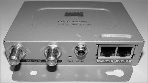
Figure 11-21: Switches send frames out the destination port only.

All good, but a problem with this arises when you need to sniff traffic on the network. Figure 11-21 illustrates this issue and a solution to it. In Figure 11-21, you can see that the sniffer isn’t seeing data coming from Host A to Host B. To solve this little snag, you can temporarily place a hub between Host A and Host B, as demonstrated in Figure 11-22.
This method will allow you to see the frames sent from Host A to Host B. The bad news, however, is that by doing this, you’ll bring down the network temporarily.
Figure 11-22: Place a hub between two hosts to troubleshoot.

The port-mirroring option allows you to place a port in Span mode so that every frame from Host A is captured by both Host B and the sniffer, as shown in Figure 11-23. This would also be a helpful option to take advantage of if you were connecting an IDS or IPS to the switch as well.
Figure 11-23: Port mirroring

Do be careful when using port mirroring because it can cause a lot of overhead on the switch and possibly crash your network. So, it’s a good idea to use this feature at strategic times and only for short periods if possible.
In this chapter, I talked about the differences between switches and bridges and how they both work at Layer 2 and create a MAC address forward/filter table in order to make decisions about whether to forward or flood a frame.
I also discussed problems that can occur if you have multiple links between bridges (switches) and how to solve these problems by using the Spanning Tree Protocol (STP).
This chapter also introduced you to the world of virtual LANs and described how switches can use them. We talked about how VLANs break up broadcast domains in a switched internetwork—a very important, necessary thing because Layer 2 switches only break up collision domains and, by default, all switches make up one large broadcast domain. I also described access links to you and went over how trunked VLANs work across a Fast Ethernet link.
Trunking is a crucial technology to understand well when you’re dealing with a network populated by multiple switches that are running several VLANs.
Remember the three switch functions. Address learning, forward/filter decisions, and loop avoidance are the functions of a switch.
Understand the main purpose of the Spanning Tree Protocol in a switched LAN. The main purpose of STP is to prevent switching loops in a network with redundant switched paths.
Remember the states of STP. The purpose of the blocking state is to prevent the use of looped paths. A port in the listening state prepares to forward data frames without populating the MAC address table. A port in the learning state populates the MAC address table but doesn’t forward data frames. A port in the forwarding state sends and receives all data frames on the bridged port. Last, a port in the disabled state is virtually nonoperational.
Remember to check a switch port’s VLAN assignment when plugging in a new host. If you plug a new host into a switch, then you must verify the VLAN membership of that port. If the membership is different than what is needed for that host, the host will not be able to reach the needed network services, such as a workgroup server.
Understand what PoE provides. Power over Ethernet was created to provide power to devices that are connected to a switch port but that are not in a place that has a power outlet—for example, an access point in a ceiling.
Write the answers to the following questions:
1. VLANs break up ________ domains in a Layer 2 switched network.
2. Switches, by default, only break up ________ domains.
3. What does trunking provide?
4. You need to power a device such as an access point or IP phone. What protocol can provide power to these devices over an Ethernet cable?
5. You plug a host into a switch port and the host receives an IP address but the user can’t get to the services it needs. What is probably the problem?
6. If a destination MAC address is not in the forward/filter table, what will the switch do with the frame?
7. What are the three switch functions at Layer 2?
8. If a frame is received on a switch port and the source MAC address is not in the forward/filter table, what will the switch do?
9. What is used at Layer 2 to prevent switching loops?
10. You need to implement a separate network for contractors and guests working at your office. Which technology should you implement?
You can find the answers in Appendix B.
You can find the answers in Appendix A.
1. You want to improve network performance by increasing the bandwidth available to hosts and limiting the size of the broadcast domains. Which of the following options will achieve this goal?
A. Managed hubs
B. Bridges
C. Switches
D. Switches configured with VLANs
2. The types of ports that can be found on a switch are___________________ and ___________________. (Choose two.)
A. VLAN Trunk Protocol
B. Access
C. 802.1Q
D. Trunk
3. Which switching technology reduces the size of a broadcast domain?
A. ISL
B. 802.1Q
C. VLANs
D. STP
4. Which of the following are IEEE versions of STP? (Choose two.)
A. 802.1x
B. VLANs
C. 802.1d
D. 802.11
E. 802.1w
5. You connect a host to a switch port, but the new host cannot log into the server that is plugged into the same switch. What could the problem be? (Choose two.)
A. The router is not configured for the new host.
B. The STP configuration on the switch is not updated for the new host.
C. The host has an invalid MAC address.
D. The switch port the host is connected to is not configured to the correct VLAN membership.
E. The STP shut down the port.
6. Which of the following are benefits of VLANs? (Choose three.)
A. They increase the size of collision domains.
B. They allow logical grouping of users by function.
C. They can enhance network security.
D. They increase the size of broadcast domains while decreasing the number of collision domains.
E. They simplify switch administration.
F. They increase the number of broadcast domains while decreasing the size of the broadcast domains.
7. Which of the following is a Layer 2 protocol used to maintain a loop-free network?
A. VTP
B. STP
C. RIP
D. CDP
8. What is the result of segmenting a network with a bridge (switch)? (Choose two.)
A. It increases the number of collision domains.
B. It decreases the number of collision domains.
C. It increases the number of broadcast domains.
D. It decreases the number of broadcast domains.
E. It makes smaller collision domains.
F. It makes larger collision domains.
9. You connect your host to a switch that is running network analyses software. However, you are not seeing any packets from the server. What do you need to implement on the switch to see all the packet information?
A. VLANs
B. STP
C. Port mirroring
D. Authentication
10. Which of the following features of a switch will allow two switches to pass VLAN network information?
A. PoE
B. VLANs
C. Trunking
D. STP
11. What are the distinct functions of Layer 2 switching that increase available bandwidth on the network? (Choose three.)
A. Address learning
B. Routing
C. Forwarding and filtering
D. Creating network loops
E. Loop avoidance
F. IP addressing
12. Which of the following statements is true?
A. A switch creates a single collision domain and a single broadcast domain. A router creates a single collision domain.
B. A switch creates separate collision domains but one broadcast domain. A router provides a separate broadcast domain.
C. A switch creates a single collision domain and separate broadcast domains. A router provides a separate broadcast domain as well.
D. A switch creates separate collision domains and separate broadcast domains. A router provides separate collision domains.
13. What does a switch do when a frame is received on an interface and the destination hardware address is unknown or not in the filter table?
A. Forwards the switch to the first available link
B. Drops the frame
C. With the exception of the source port, floods the network with the frame looking for the device
D. Sends back a message to the originating station asking for a name resolution
14. If a switch receives a frame, and the source MAC address is not in the MAC address table but the destination address is, what will the switch do with the frame?
A. Discard it and send an error message back to the originating host
B. Flood the network with the frame
C. Add the source address and port to the MAC address table and forward the frame out the destination port
D. Add the destination to the MAC address table and then forward the frame
15. When would you configure VTP on a switch?
A. When you have hubs connected in your network
B. When you have redundant links between switches
C. When you have multiple hosts in multiple VLANs and you want to share all the data between hosts without a router
D. When you have multiple switches with multiple VLANs and you want to share the VLAN database from one switch to all the others
16. When is STP said to be converged on the root bridge? (Choose two.)
A. When all ports are in the forwarding state
B. When all ports are in the blocking state
C. When all ports are in the listening state
D. When all ports are in the learning state
17. In which two states is the MAC address table populated with addresses?
A. Blocked
B. Listening
C. Learning
D. Forwarding
18. You have multiple departments all connected to switches, with cross-over cables connecting the switches together. However, response time on the network is still very slow even though you have upgraded from hubs to switches. What technology should you implement to improve response time on the networks?
A. STP
B. VLANs
C. Convergence
D. OSPF
19. If you are configuring voice VLANs, which of the following should you configure on the switch ports to provide a higher precedence to voice traffic over data traffic to improve sound quality?
A. Access VLANs
B. VTP
C. QoS
D. STP
20. What is a disadvantage of using port spanning?
A. It breaks up broadcast domains on all ports.
B. It can create overhead on the switch.
C. It makes the switch one large collision domain.
D. It makes the switch fast between only two ports instead of all ports.