
CHAPTER 11
Networking Fundamentals
This chapter presents the following:
• Data communications foundations
• Networking protocols
• Local, metropolitan, and wide area networks
The Internet…it’s a series of tubes.
Before we dive into communications and network security, it makes sense to review (and maybe pick up a bit of new information on) the fundamentals of data communications networks. Data communications and networking are complex topics, mainly because so many technologies are involved. Our current technologies are constantly evolving, and every month there seems to be new “emerging” ones that we have to learn, understand, implement, and secure. As security professionals, we need a solid grasp of networking software, protocols, services, and devices. We have to be able to identify and deal with interoperability issues (ideally before developing or acquiring a new system). Armed with all this knowledge and skill, we need to anticipate or discover vulnerabilities, both in individual components and in their interactions with each other, and devise effective controls for them. This can be a challenging task. However, if you are knowledgeable, have a solid practical skill set, and are willing to continue to learn, you can have more career opportunities than you know what to do with.
In this chapter we will start with the basics of data communications and networking, and then build upon them and identify many of the security issues that are involved. We’ll follow up in the next chapter with a discussion of wireless technologies that take the place of the cables described in this chapter. Then, in Chapter 13 we’ll dive into the protocols that drive the Internet. This will set the stage for understanding how we secure this hodgepodge of technologies, the focus of Chapters 14 and 15.
Data Communications Foundations
Data communications have made amazing advances in a relatively short period of time. In the beginning of the Computer Age, mainframes were the name of the game. They were isolated powerhouses, and many had “dumb” terminals hanging off them, but this was not true networking. In the late 1960s and early 1970s, some technical researchers came up with ways of connecting all the mainframes and Unix systems to enable them to communicate. This marked the Internet’s first baby steps.
While access to shared resources was a major drive in the evolution of networking, today the infrastructure that supports these shared resources and the services these components provide is really the secret to the secret sauce. As we will see, networks are made up of routers, switches, servers, proxies, firewalls, intrusion detection/prevention systems (IDS/IPSs), storage systems, virtual private network (VPN) concentrators, public key infrastructure, private branch exchanges (PBXs), and more. While functionality is critical, there are other important requirements that need to be understood when architecting a network, such as scalability, redundancy, performance, security, manageability, and maintainability.
Infrastructure provides foundational capabilities that support almost every aspect of our lives. When most people think of technology, they focus on the end systems that they interact with—laptops, mobile phones, tablet PCs, workstations, and so on—or the applications they use, such as e-mail, Facebook, websites, instant messaging, Twitter, and online banking. Most people do not even give a thought to how this stuff works under the covers, and many people do not fully realize all the other stuff that is dependent upon technology: medical devices, critical infrastructure, weapon systems, transportation, satellites, telephony, and so forth. People say it is love that makes the world go around, but let them experience one day without the Internet. We are all more dependent upon the Matrix than we fully realize, and as security professionals we need to not only understand the Matrix but also secure it.
Before we get into the weeds of actual devices, systems, and services, it will be helpful to have a reference model so that we can put like pieces in the same bin. This will allow us to compare things that perform similar functions so that we can better see how they differ and what those differences may mean for security. Let’s start off by introducing the two most common models for understanding networked systems: the OSI model and the TCP/IP model.
Network Reference Models
In the early 1980s, the International Organization for Standardization (as it is referred to internationally, but commonly abbreviated as ISO) worked to develop a protocol set that would be used by all vendors throughout the world to allow the interconnection of network devices. This movement was fueled with the hopes of ensuring that all vendor products and technologies could communicate and interact across international and technical boundaries. The actual protocol set did not catch on as a standard, but the Open Systems Interconnection (OSI) reference model was adopted and is used as an abstract framework to which most operating systems and protocols adhere.
Many people think that the OSI reference model arrived at the beginning of the computing age as we know it and helped shape and provide direction for many, if not all, networking technologies. However, this is not true. In fact, it was introduced in 1984, at which time the basics of the Internet had already been developed and implemented, and the basic Internet protocols had been in use for many years.
The Transmission Control Protocol/Internet Protocol (TCP/IP) suite actually has its own model that predates the OSI model by several years. As a bit of background, the Internet as we know it grew from the Advanced Research Project Agency Network (ARPANET) program that started in the late 1960s. By 1978, ARPANET researchers realized that a monolithic approach to networking was not going to scale well. That’s when they split what had until then been known as the Transmission Control Program (which encompassed all aspects of getting data from point A to point B) into two distinct layers: TCP and IP. Everything that happened below IP was the domain of network access engineers, and everything above TCP was the domain of application developers. The idea caught on and the TCP/IP reference model was born. It is often used today when examining and understanding networking issues. Figure 11-1 shows the differences between the OSI and TCP/IP networking models. In this chapter, we will focus on the OSI model.
 NOTE
NOTE
The host-to-host layer is sometimes called the transport layer in the TCP/IP model. The application layer in the TCP/IP architecture model is equivalent to a combination of the application, presentation, and session layers in the OSI model.
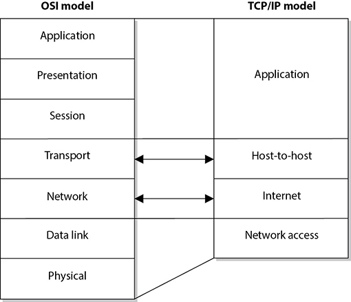
Figure 11-1 The OSI and TCP/IP networking models
Protocols
Before we delve into the details of each layer of the OSI model, we need to examine the concept of network protocols. A network protocol is a standard set of rules that determines how systems will communicate across networks. Two different systems that use the same protocol can communicate and understand each other despite their differences, similar to how two people can communicate and understand each other by using the same language.
The OSI reference model, as described by ISO Standard 7498-1, provides important guidelines used by vendors, engineers, developers, and others. The model segments the networking tasks, protocols, and services into different layers. Each layer has its own responsibilities regarding how two computers communicate over a network. Each layer has certain functionalities, and the services and protocols that work within that layer fulfill them.
The OSI model’s goal is to help vendors develop products that will work within an open network architecture. An open network architecture is one that no vendor owns, that is not proprietary, and that can easily integrate various technologies and vendor implementations of those technologies. Vendors have used the OSI model as a jumping-off point for developing their own networking frameworks. These vendors use the OSI model as a blueprint and develop their own protocols and services to produce functionality that is different from, or overlaps, that of other vendors. However, because these vendors use the OSI model as their starting place, integration of other vendor products is an easier task, and the interoperability issues are less burdensome than if the vendors had developed their own networking framework from scratch.
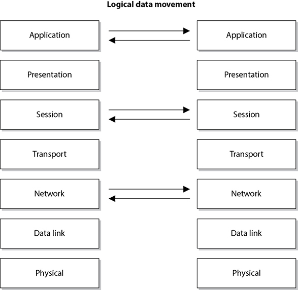
Although computers communicate in a physical sense (electronic signals are passed from one computer over a wire to the other computer), they also communicate through logical channels. Each protocol at a specific OSI layer on one computer communicates with a corresponding protocol operating at the same OSI layer on another computer. This happens through encapsulation.
Here’s how encapsulation works: A message is constructed within a program on one computer and is then passed down through the network protocol’s stack. A protocol at each layer adds its own information to the message, creating a protocol data unit (PDU). Thus, the message grows in size as it goes down the protocol stack. The message is then sent to the destination computer, and the encapsulation is reversed by taking the packet apart through the same steps used by the source computer that encapsulated it. At the data link layer, the PDU pertaining to the data link layer is deconstructed, and the packet is sent up to the next layer. Then at the network layer, the network layer PDU is stripped and processed, and the message is again passed up to the next layer, and so on. This is how computers communicate logically. The information stripped off at the destination computer informs it how to interpret and process the packet properly. Data encapsulation is shown in Figure 11-2.
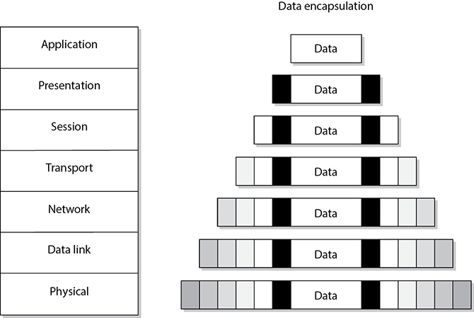
Figure 11-2 Each OSI layer protocol adds its own information to the data packet.
A protocol at each layer has specific responsibilities and control functions it performs, as well as data format syntaxes it expects. Each layer has a special interface (connection point) that allows it to interact with three other layers: (1) communications from the interface of the layer above it, (2) communications to the interface of the layer below it, and (3) communications with the same layer in the interface of the target packet address. The control functions, added by the protocols at each layer, are in the form of headers and trailers of the packet.
The benefit of modularizing these layers, and the functionality within each layer, is that various technologies, protocols, and services can interact with each other and provide the proper interfaces to enable communications. This means a computer can use an application protocol developed by Microsoft, a transport protocol developed by Apple, and a data link protocol developed by Cisco to construct and send a message over a network. The protocols, technologies, and computers that operate within the OSI model are considered open systems. Open systems are capable of communicating with other open systems because they implement international standard protocols and interfaces. The specification for each layer’s interface is very structured, while the actual code that makes up the internal part of the software layer is not defined. This makes it easy for vendors to write plug-ins in a modularized manner. Systems are able to integrate the plug-ins into the network stack seamlessly, gaining the vendor-specific extensions and functions.
Understanding the functionalities that take place at each OSI layer and the corresponding protocols that work at those layers helps you understand the overall communication process between computers. Once you understand this process, a more detailed look at each protocol will show you the full range of options each protocol provides and the security weaknesses embedded into each of those options.
Application Layer
The application layer, layer 7, works closest to the user and provides file transmissions, message exchanges, terminal sessions, and much more. This layer does not include the actual applications, but rather the protocols that support the applications. When an application needs to send data over the network, it passes instructions and the data to the protocols that support it at the application layer. This layer processes and properly formats the data and passes it down to the next layer within the OSI model. This happens until the data the application layer constructed contains the essential information from each layer necessary to transmit the data over the network. The data is then put on the network cable and transmitted until it arrives at the destination computer.
As an analogy, let’s say that you write a letter that you would like to send to your congressman. Your job is to write the letter, your clerk’s job is to figure out how to get it to him, and the congressman’s job is to read your letter and respond to it. You (the application) create the content (message) and hand it to your assistant (application layer protocol). Your assistant puts the content into an envelope, writes the congressman’s address on the envelope (inserts headers and trailers), and puts it into the mailbox (passes it on to the next protocol in the network stack). When your assistant checks the mailbox a week later, there is a letter from the congressman (the remote application) addressed to you. Your assistant opens the envelope (strips off headers and trailers) and gives you the message (passes the message up to the application).
Some examples of the protocols working at the application layer are the Simple Mail Transfer Protocol (SMTP), the Hypertext Transfer Protocol (HTTP), and the Line Printer Daemon (LPD) protocol. Figure 11-3 shows how applications communicate with the underlying protocols through application programming interfaces (APIs). If a user makes a request to send an e-mail message through her e-mail client Outlook, the e-mail client sends this information to SMTP. SMTP adds its information to the user’s message and passes it down to the presentation layer.
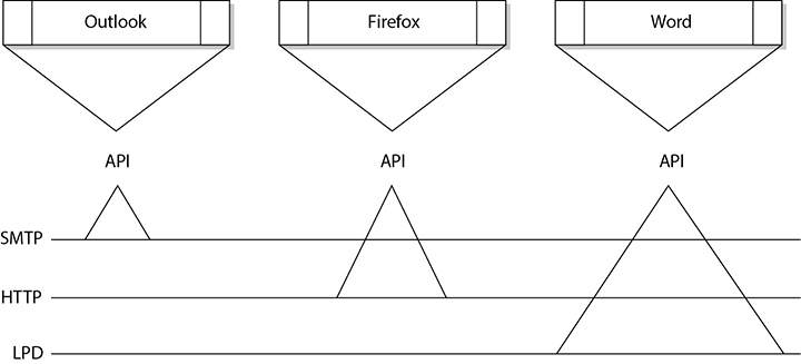
Figure 11-3 Applications send requests to an API, which is the interface to the supporting protocol.
Presentation Layer
The presentation layer, layer 6, receives information from the application layer protocol and puts it in a format that any process operating at the same layer on a destination computer following the OSI model can understand. This layer provides a common means of representing data in a structure that can be properly processed by the end system. This means that when a user creates a Word document and sends it out to several people, it does not matter whether the receiving computers have different word processing programs; each of these computers will be able to receive this file and understand and present it to its user as a document. It is the data representation processing that is done at the presentation layer that enables this to take place. For example, when a Windows 10 computer receives a file from another computer system, information within the file’s header indicates what type of file it is. The Windows 10 operating system has a list of file types it understands and a table describing what program should be used to open and manipulate each of these file types. For example, suppose the sender e-mails a Portable Document Format (PDF) file created in Word and the receiver uses a Linux system. The receiver can open this file because the presentation layer on the sender’s system encoded the file and added a descriptive header in accordance with the Multipurpose Internet Mail Extensions (MIME) standards, and the receiver’s computer interprets the header’s MIME type (Content-Type: application/pdf), decodes the file, and knows to open it with its PDF viewer application.
The presentation layer is concerned not with the meaning of data but with the syntax and format of that data. It works as a translator, translating the format an application is using to a standard format used for passing messages over a network. If a user uses a graphics application to save a file, for example, the graphic could be a Tagged Image File Format (TIFF), Graphic Interchange Format (GIF), or Joint Photographic Experts Group (JPEG) format. The presentation layer adds information to tell the destination computer the file type and how to process and present it. This way, if the user sends this graphic to another user who does not have the same graphics application, the receiving user’s operating system can still present the graphic because it has been saved in a standard format. Figure 11-4 illustrates the conversion of a file into different standard file types.
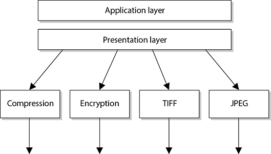
Figure 11-4 The presentation layer receives data from the application layer and puts it into a standard format.
This layer also handles data compression and encryption issues. If a program requests a certain file to be compressed and encrypted before being transferred over the network, the presentation layer provides the necessary information for the destination computer. It provides information on how the file was encrypted and/or compressed so that the receiving system knows what software and processes are necessary to decrypt and decompress the file. Let’s say Sara compresses a file using WinZip and sends it to you. When your system receives this file, it looks at data within the header (Content-Type: application/zip) and knows what application can decompress the file. If your system has WinZip installed, then the file can be decompressed and presented to you in its original form. If your system does not have an application that understands the compression/decompression instructions, the file will be presented to you with an unassociated icon.
Session Layer
When two applications need to communicate or transfer data between themselves, a connection may need to be set up between them. The session layer, layer 5, is responsible for establishing a connection between the two applications, maintaining it during the transfer of data, and controlling the release of this connection. A good analogy for the functionality within this layer is a telephone conversation. When Kandy wants to call a friend, she uses the telephone. The telephone network circuitry and protocols set up the connection over the telephone lines and maintain that communication path, and when Kandy hangs up, they release all the resources they were using to keep that connection open.
Similar to how telephone circuitry works, the session layer works in three phases: connection establishment, data transfer, and connection release. It provides session restart and recovery if necessary and provides the overall maintenance of the session. When the conversation is over, this path is broken down and all parameters are set back to their original settings. This process is known as dialog management. Figure 11-5 depicts the three phases of a session. Some protocols that work at this layer are the Layer 2 Tunneling Protocol (L2TP), Point-to-Point Tunneling Protocol (PPTP), and Remote Procedure Call (RPC).

Figure 11-5 The session layer sets up the connection, maintains it, and tears it down once communication is completed.
The session layer protocol can enable communication between two applications to happen in three different modes:
• Simplex Communication takes place in one direction, though in practice this is very seldom the case.
• Half-duplex Communication takes place in both directions, but only one application can send information at a time.
• Full-duplex Communication takes place in both directions, and both applications can send information at the same time.
Many people have a hard time understanding the difference between what takes place at the session layer versus the transport layer because their definitions sound similar. Session layer protocols control application-to-application communication, whereas the transport layer protocols handle computer-to-computer communication. For example, if you are using a product that is working in a client/server model, in reality you have a small piece of the product on your computer (client portion) and the larger piece of the software product is running on a different computer (server portion). The communication between these two pieces of the same software product needs to be controlled, which is why session layer protocols even exist. Session layer protocols take on the functionality of middleware, which allows software on two different computers to communicate.
Session layer protocols provide interprocess communication channels, which allow a piece of software on one system to call upon a piece of software on another system without the programmer having to know the specifics of the software on the receiving system. The programmer of a piece of software can write a function call that calls upon a subroutine. The subroutine could be local to the system or be on a remote system. If the subroutine is on a remote system, the request is carried over a session layer protocol. The result that the remote system provides is then returned to the requesting system over the same session layer protocol. This is how RPC works. A piece of software can execute components that reside on another system. This is the core of distributed computing.
NOTE
One security issue common to RPC (and similar interprocess communication systems) is improperly configured authentication or the use of unencrypted communications.
Session layer protocols are the least used protocols in a network environment; thus, many of them should be disabled on systems to decrease the chance of them being exploited. RPC, NetBIOS, and similar distributed computing calls usually only need to take place within a network; thus, firewalls should be configured so this type of traffic is not allowed into or out of a network. Firewall filtering rules should be in place to stop this type of unnecessary and dangerous traffic.
Transport Layer
When two computers are going to communicate through a connection-oriented protocol, they first agree on how much information each computer will send at a time, how to verify the integrity of the data once received, and how to determine whether a packet was lost along the way. The two computers agree on these parameters through a handshaking process at the transport layer, layer 4. The agreement on these issues before transferring data helps provide more reliable data transfer, error detection, correction, recovery, and flow control, and it optimizes the network services needed to perform these tasks. The transport layer provides end-to-end data transport services and establishes the logical connection between two communicating computers.
NOTE
Connection-oriented protocols, such as Transmission Control Protocol (TCP), provide reliable data transmission when compared to connectionless protocols, such as User Datagram Protocol (UDP). This distinction is covered in more detail in the “Internet Protocol Networking” section, later in the chapter.
The functionality of the session and transport layers is similar insofar as they both set up some type of session or virtual connection for communication to take place. The difference is that protocols that work at the session layer set up connections between applications, whereas protocols that work at the transport layer set up connections between computer systems. For example, we can have three different applications on computer A communicating with three applications on computer B. The session layer protocols keep track of these different sessions. You can think of the transport layer protocol as the bus. It does not know or care what applications are communicating with each other. It just provides the mechanism to get the data from one system to another.
The transport layer receives data from many different applications and assembles the data into a stream to be properly transmitted over the network. The main protocols that work at this layer are the Transmission Control Protocol (TCP) and the User Datagram Protocol (UDP). Information is passed down from different entities at higher layers to the transport layer, which must assemble the information into a stream, as shown in Figure 11-6. The stream is made up of the various data segments passed to it. Just like a bus can carry a variety of people, the transport layer protocol can carry a variety of application data types.
NOTE
Different references can place specific protocols at different layers. For example, many references place the Transport Layer Security (TLS) protocol in the session layer, while other references place it in the transport layer. Neither placement is right or wrong. The OSI model tries to draw boxes around reality, but some protocols straddle the different layers.
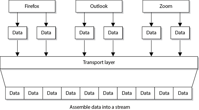
Figure 11-6 TCP formats data from applications into a stream to be prepared for transmission.
Network Layer
The main responsibilities of the network layer, layer 3, are to insert information into the packet’s header so it can be properly addressed and routed, and then to actually route the packet to its proper destination. In a network, many routes can lead to one destination. The protocols at the network layer must determine the best path for the packet to take. Routing protocols build and maintain their routing tables. These tables are maps of the network, and when a packet must be sent from computer A to computer M, the protocols check the routing table, add the necessary information to the packet’s header, and send it on its way.
The protocols that work at this layer do not ensure the delivery of the packets. They depend on the protocols at the transport layer to catch any problems and resend packets if necessary. The Internet Protocol (IP) is the predominant protocol working at the network layer, although other routing and routed protocols work there as well. Some of the other protocols are the Internet Control Message Protocol (ICMP), Routing Information Protocol (RIP), Open Shortest Path First (OSPF), Border Gateway Protocol (BGP), and Internet Group Management Protocol (IGMP). Figure 11-7 shows that a packet can take many routes and that the network layer enters routing information into the header to help the packet arrive at its destination.
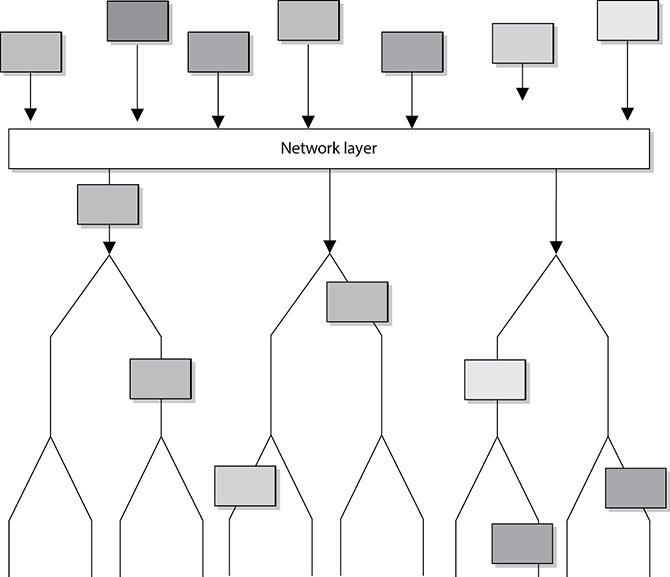
Figure 11-7 The network layer determines the most efficient path for each packet to take.
Data Link Layer
As we continue down the protocol stack, we are getting closer to the actual transmission channel (e.g., network wire) over which all the data will travel. The network layer has already figured out how to route the packet through the various network devices to its final destination, but we still need to get the data over to the next, directly connected device. This happens at the data link layer, layer 2.
Different networking technologies, as we will shortly discuss in detail, can use different protocols, network interface cards (NICs), cables, and transmission methods. Each of these components has a different header data format structure, and they interpret electromagnetic signals in different ways. The data link layer is where the network stack knows in what format the data frame must be in order to transmit it properly over Ethernet, wireless, or frame relay links. If the network is an Ethernet network, for example, all the computers will expect packet headers to be a certain length, the flags to be positioned in certain field locations within the header, and the trailer information to be in a certain place with specific fields. Compared to Ethernet, frame relay network technology has different frame header lengths, flag values, and header formats.
The data link layer can be further divided into two functional sublayers: Logical Link Control (LLC), whose job is to interface with the network layer above, and Media Access Control (MAC), which is designed to interface with the physical layer below. Let’s drill into this a bit. The LLC sublayer, which is defined in the ISO/IEC 8802-2 standard for Ethernet networks, receives a message (say, an IP packet) from layer 3 and negotiates the manner in which it should be sent out over the network link. This could include keeping track of which layer 3 protocol was used, determining what kind of service (e.g., connectionless or connection-oriented) will be used, and performing flow control so the link doesn’t get saturated. The LLC sublayer then hands over the data to the MAC sublayer, which encapsulates it into a frame of the right type depending on the networking technology in use by the physical layer. Generally, LLC is implemented in software (as a device driver), while MAC is built in firmware on a physical device. Figure 11-8 shows these two sublayers that make up the data link layer.
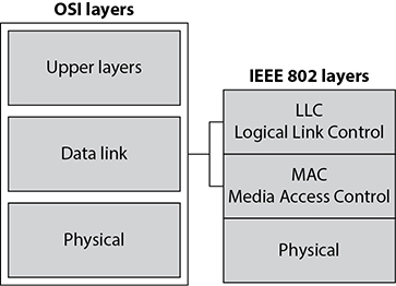
Figure 11-8 The data link layer is made up of two sublayers.
As data is passed down the network stack, it has to go from the network layer to the data link layer. The protocol at the network layer does not know if the underlying network is Ethernet, wireless, or frame relay—it does not need to have this type of insight. The protocol at the network layer just adds its header and trailer information to the packet and passes it on to the next layer, which is the LLC sublayer. The LLC sublayer takes care of flow control and error checking. Data coming from the network layer passes down through the LLC sublayer and goes to the MAC sublayer. The technology at the MAC sublayer knows if the network is Ethernet, wireless, or frame relay, so it knows how to put the last header and trailer on the packet before it “hits the wire” for transmission.
Some of the protocols that work at the data link layer are the Point-to-Point Protocol (PPP), Asynchronous Transfer Mode (ATM), Layer 2 Tunneling Protocol (L2TP), Fiber Distributed Data Interface (FDDI), Ethernet, and Token Ring.
Each network technology (Ethernet, wireless, frame relay, and so on) defines the compatible physical transmission type (coaxial, twisted pair, fiber, wireless) that is required to enable network communication. Each network technology also has defined electronic signaling and encoding patterns. For example, if we were transmitting a bit with the value of 1 over an Ethernet network, the MAC sublayer would tell the physical layer to create a +0.5-volt electric signal. In the “language of Ethernet” this means that 0.5 volts is the encoding value for a bit with the value of 1. If the next bit the MAC sublayer receives is 0, the MAC layer would tell the physical layer to transmit 0 volts. The different network types will have different encoding schemes.
NICs bridge the data link and physical layers. Data is passed down through the first six layers and reaches the NIC at the data link layer. Depending on the network technology being used, the NIC encodes the bits at the data link layer, which are then turned into electricity states at the physical layer and placed onto the wire for transmission.
 EXAM TIP
When the data link layer applies the last header and trailer to the data message, this is referred to as framing. The unit of data is now called a frame.
Physical Layer
The physical layer, layer 1, converts bits into electromagnetic signals for transmission. Signals and voltage schemes have different meanings for different LAN and WAN technologies, as covered earlier. If a user sends data through the radio transceiver on a smartphone, the data format, electrical signals, and control functionality are much different than if that user sends data through an Ethernet NIC and onto an unshielded twisted pair (UTP) wire for LAN communication. The mechanisms that control this data going onto the radio waves, or the UTP wire, work at the physical layer. This layer controls synchronization, data rates, line noise, and transmission techniques. Specifications for the physical layer include the timing of voltage changes, voltage levels, and the physical connectors for electrical, optical, and mechanical transmission.
EXAM TIP
To remember all the layers within the OSI model in the correct order, memorize “All People Seem To Need Data Processing.” Remember that you are starting at layer 7, the application layer, at the top.
Functions and Protocols in the OSI Model
For the CISSP exam, you will need to know the functionality that takes place at the different layers of the OSI model, along with specific protocols that work at each layer. The following is a quick overview of each layer and its components.
Application
The protocols at the application layer handle file transfer, virtual terminals, network management, and fulfilling networking requests of applications. A few of the protocols that work at this layer include
• File Transfer Protocol (FTP)
• Network Time Protocol (NTP)
• Simple Mail Transfer Protocol (SMTP)
• Internet Message Access Protocol (IMAP)
• Hypertext Transfer Protocol (HTTP)
Presentation
The services of the presentation layer handle translation into standard formats, data compression and decompression, and data encryption and decryption. No protocols work at this layer, just services. The following lists some of the presentation layer standards:
• American Standard Code for Information Interchange (ASCII)
• Tagged Image File Format (TIFF)
• Joint Photographic Experts Group (JPEG)
• Motion Picture Experts Group (MPEG)
• Musical Instrument Digital Interface (MIDI)
Session
The session layer protocols set up connections between applications; maintain dialog control; and negotiate, establish, maintain, and tear down the communication channel. Some of the protocols that work at this layer include
• Layer 2 Tunneling Protocol (L2TP)
• Network Basic Input Output System (NetBIOS)
• Password Authentication Protocol (PAP)
• Point-to-Point Tunneling Protocol (PPTP)
• Remote Procedure Call (RPC)
Transport
The protocols at the transport layer handle end-to-end transmission and segmentation of a data stream. The following protocols work at this layer:
• Transmission Control Protocol (TCP)
• User Datagram Protocol (UDP)
• Stream Control Transmission Protocol (SCTP)
• Resource Reservation Protocol (RSVP)
• QUIC (not an acronym)
Network
The responsibilities of the network layer protocols include internetworking service, addressing, and routing. The following lists some of the protocols that work at this layer:
• Internet Protocol (IP)
• Internet Control Message Protocol (ICMP)
• Internet Group Management Protocol (IGMP)
• Routing Information Protocol (RIP)
• Open Shortest Path First (OSPF)
Data Link
The protocols at the data link layer convert data into LAN or WAN frames for transmission and define how a computer accesses a network. This layer is divided into the Logical Link Control (LLC) and the Media Access Control (MAC) sublayers. Some protocols that work at this layer include the following:
• Address Resolution Protocol (ARP)
• Reverse Address Resolution Protocol (RARP)
• Serial Line Internet Protocol (SLIP)
• Ethernet (IEEE 802.3)
• Wireless Ethernet (IEEE 802.11)
Physical
Network interface cards and drivers convert bits into electrical signals and control the physical aspects of data transmission, including optical, electrical, and mechanical requirements. The following are some of the standard interfaces at this layer:
• RS/EIA/TIA-422, RS/EIA/TIA-423, RS/EIA/TIA-449, RS/EIA/TIA-485
• 10Base-T, 10Base2, 10Base5, 100Base-TX, 100Base-FX, 100Base-T, 1000Base-T, 1000Base-SX
• Integrated Services Digital Network (ISDN)
• Digital subscriber line (DSL)
• Synchronous Optical Networking (SONET)
Tying the Layers Together
The OSI model is used as a framework for many network-based products and is used by many types of vendors. Various types of devices and protocols work at different parts of this seven-layer model. The main reason that a Cisco switch, a Microsoft web server, a Barracuda firewall, and a Belkin wireless access point can all communicate properly on one network is because they all work within the OSI model. They do not have their own individual ways of sending data; they follow a standardized manner of communication, which allows for interoperability and allows a network to be a network. If a product does not follow the OSI model, it will not be able to communicate with other devices on the network because the other devices will not understand its proprietary way of communicating.
The different device types work at specific OSI layers. For example, computers can interpret and process data at each of the seven layers, but routers can understand information only up to the network layer because a router’s main function is to route packets, which does not require knowledge about any further information within the packet. A router peels back the header information until it reaches the network layer data, where the routing and IP address information is located. The router looks at this information to make its decisions on where the packet should be routed. Bridges and switches understand only up to the data link layer, and repeaters understand traffic only at the physical layer. So if you hear someone mention a “layer 3 device,” the person is referring to a device that works at the network layer. A “layer 2 device” works at the data link layer. Figure 11-9 shows what layer of the OSI model each type of device works within.
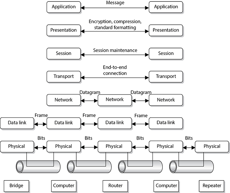
Figure 11-9 Each device works at a particular layer within the OSI model.
NOTE
Some techies like to joke that all computer problems reside at layer 8. The OSI model does not have an eighth layer, and what these people are referring to is the user of a computer. So if someone states that there is a problem at layer 8, this is code for “the user is the problem.”
Let’s walk through an example. You just logged into a website and the landing page includes an image that your web browser automatically requests from the server. The web server now has to move this file over the network to your computer, so it generates an HTTP response, which includes a handle to the file, and hands it over to the presentation layer for encoding. HTTP doesn’t directly handle binary files like JPEG images, so the file must first be “serialized” or converted to a sequence of printable characters, which is what the presentation layer does.
Once the response is “presentable” (pardon the pun), the presentation layer hands it to the session layer to figure out which of the clients currently communicating with the server should receive this image; the session layer figures out that it is for you and that you have been authenticated. The session layer then forwards the response to the transport layer, telling it the connection (or network socket) on which it should go out. Based on this connection identifier, the transport layer encapsulates the payload it just got from the session layer in a TCP datagram (which is what HTTP runs on), writes the protocol and port numbers in its header, and passes it on to layer 3.
The image you’re requesting is quite large, so the network layer breaks it up into a numbered sequence of chunks, encapsulates each in its own IP packet, figures out how to route the packets, and then hands each to the data link layer. Layer 2 takes each packet and, based on its destination IP address, determines the next hop on its journey back to you, which is probably the DMZ firewall. It encapsulates the packet into an Ethernet frame, writes the MAC address of the firewall in it, and sends it down to the physical layer, which turns the 1’s and 0’s into electric currents on the network cable. And, just like that, your image starts its journey toward your screen.
Local Area Networks
Now that we’ve taken a quick look down all seven layers of the OSI model, let’s circle back and take a more detailed look from the ground up. If you connect two general-purpose computers that are right next to each other, you create a local area network. A local area network (LAN) is a group of interconnected computers in close physical proximity to each other. A LAN is the basic building block for most organizational networks. As we’ll shortly see, there are multiple ways to build LANs both physically and logically. In the following sections, we’ll discuss the various technologies that allow us to physically interconnect devices.
Network Topology
The arrangement of computers and devices is called a network topology. Topology refers to the manner in which a network is physically connected and shows the layout of resources and systems. A difference exists between the physical network topology and the logical topology. A network can be configured as a physical star but work logically as a ring, as in the Token Ring technology.
The best topology for a particular network depends on such things as how nodes are supposed to interact; which protocols are used; the types of applications that are available; the reliability, expandability, and physical layout of a facility; existing wiring; and the technologies implemented. The wrong topology or combination of topologies can negatively affect the network’s performance, productivity, and growth possibilities.
This section describes the basic types of network topologies. Most networks are much more complex and are usually implemented using a combination of topologies.
Bus Topology
In a simple bus topology, a single cable runs the entire length of the network. Nodes are attached to the network through drop points on this cable. Data communications transmit the length of the medium, and each packet transmitted has the capability of being “looked at” by all nodes. Each node decides to accept or ignore the packet, depending upon the packet’s destination address.
Bus topologies are of two main types: linear and tree. The linear bus topology has a single cable with nodes attached. A tree topology has branches from the single cable, and each branch can contain many nodes. In simple implementations of a bus topology, if one workstation fails, other systems can be negatively affected because of the degree of interdependence. In addition, because all nodes are connected to one main cable, the cable itself becomes a potential single point of failure.
Bus topologies were common years ago on the first Ethernet networks. Today, you are very unlikely to encounter them in local area networks. However, this topology is prevalent in vehicular networks, of which the Controller Area Network (CAN) bus is by far the most popular standard.
Star Topology
In a star topology, all nodes connect to a central device such as a switch. Each node has a dedicated link to the central device. The central device needs to provide enough throughput that it does not become a detrimental bottleneck for the network as a whole. Because a central device is required, it is a potential single point of failure, so redundancy may need to be implemented. Switches can be configured in flat or hierarchical implementations so larger organizations can use them.
When one workstation fails on a star topology, it does not affect other systems, as in the bus topologies. In a star topology, each system is not as dependent on others as it is dependent on the central connection device. This topology generally requires less cabling than other types of topologies. As a result, cut cables are less likely, and detecting cable problems is an easier task.
Mesh Topology
In a mesh topology, all systems and resources are connected to each other in a way that does not follow the uniformity of the previous topologies, as shown in Figure 11-10. This arrangement is usually a network of interconnected routers and switches that provides multiple paths to all the nodes on the network. In a full mesh topology, every node is directly connected to every other node, which provides a great degree of redundancy. A typical Internet of Things (IoT) home automation network using ZigBee is an example of a full mesh topology. In a partial mesh topology, every node is not directly connected. The Internet is an example of a partial mesh topology.

Figure 11-10 In a mesh topology, each node is connected to all other nodes, which provides for redundant paths.
Ring Topology
A ring topology has a series of devices connected by unidirectional transmission links, as shown in Figure 11-11. These links form a closed loop and do not connect to a central system, as in a star topology. In a physical ring formation, each node is dependent upon the preceding nodes. In simple networks, if one system fails, all other systems could be negatively affected because of this interdependence. Compensating for such failures, coupled with the difficulty of installing a ring network in the first place, makes ring topologies more expensive than other topologies. Although you have to know about ring topologies for the CISSP exam, you are extremely unlikely to find them in the real world. Still, who knows? Maybe one day they’ll make a comeback.

Figure 11-11 A ring topology forms a closed-loop connection.
Network Topologies Summary
A summary of the different network topologies and their important characteristics is provided in Table 11-1.
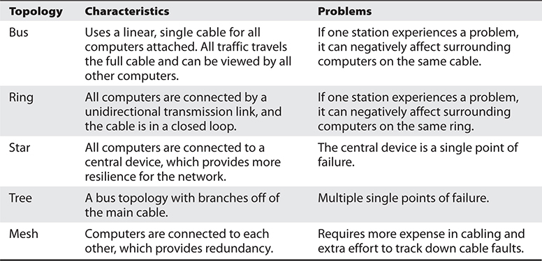
Table 11-1 Summary of Network Topologies
Medium Access Control Mechanisms
The physical topology of a network is the lower layer, or foundation, of a network. It determines what type of physical media will be used to connect network devices and what these connections look like. Medium access control (MAC) mechanisms deal with how computer systems communicate over these media and are built into the network interfaces. MAC mechanisms set up the rules of how computers will communicate on a LAN, how errors are handled, the maximum transmission unit (MTU) size of frames, and much more. These rules enable all computers and devices to communicate and recover from problems, and enable users to be productive in accomplishing their networking tasks. Each participating entity needs to know how to communicate properly so all other systems will understand the transmissions, instructions, and requests.
LAN MAC mechanisms reside at the data link layer of the OSI model. Remember that as a message is passed down through a network stack, it is encapsulated by the protocols and services at each layer. When the data message reaches the data link layer, the protocol at this layer adds the necessary headers and trailers that will allow the message to traverse a specific type of network (Ethernet, Token Ring, FDDI, etc.)
No matter what type of medium access technology is being used, the main resource that has to be shared by all systems and devices on the network is the network transmission channel. This transmission channel could be coaxial cabling, UTP cabling, optical fibers, or free space (e.g., using radio waves). There must be methods in place to make sure that each system gets its fair share of access to the channel, that the system’s data is not corrupted during transmission, and that there is a way to control traffic in peak times. Let’s take a closer look at the three most common approaches to MAC: carrier sense multiple access, Token Ring, and polling.
Carrier Sense Multiple Access
By far, the most common approach to MAC is called carrier sense multiple access (CSMA), which provides a standard way to access the shared medium, communicate, and recover from any errors that may occur. A transmission is called a carrier, so if a computer is transmitting frames, it is performing a carrier activity. Despite their best efforts, networked computers sometimes talk over each other, which creates what is called a collision. Think about it: it takes time for electromagnetic signals to move from point A (where one transmitter sits) to point B (where another computer also wants to transmit). Both computers listen to the medium and, detecting no other traffic on it, simultaneously transmit their messages. Sometime later, these messages meet each other on the medium and collide, or corrupt each other. There are two variants of CSMA with which you should be familiar: collision detection (CSMA/CD) and collision avoidance (CSMA/CA).
When computers use the carrier sense multiple access with collision detection (CSMA/CD) protocol, they monitor the transmission activity, or carrier activity, on the wire so they can determine when would be the best time to transmit data. Each node monitors the wire continuously and waits until the wire is free before it transmits its data. As an analogy, consider several people gathered in a group talking here and there about this and that. If a person wants to talk, she usually listens to the current conversation and waits for a break before she proceeds to talk. If she does not wait for the first person to stop talking, she will be speaking at the same time as the other person, and the people around them may not be able to understand fully what each is trying to say. If a computer puts frames on the wire and its frames collide with another computer’s frames, it will abort its transmission and alert all other stations that a collision just took place. All stations will start a random collision timer to force a delay before they attempt to transmit data. This random collision timer is called the back-off algorithm. CSMA/CD was important in the early days of Ethernet LANs when hubs and bridges were common, but is now largely deprecated.
The other variant of CSMA is carrier sense multiple access with collision avoidance (CSMA/CA), in which all stations with data to transmit first check the medium to see if it’s quiet. If it is, they send their data. If it isn’t, they start a random timer before they check again. In some implementations, the station wishing to send data first sends a request to send (RTS) frame to a controller or the destination and then waits for a clear to send (CTS) frame before transmitting its data. CSMA/CA is most commonly used in wireless networks.
Token Passing
Some of North America’s indigenous people devised a clever way to ensure only one of them spoke (and was not interrupted) at meetings. It was called the talking stick, and only the one holding it was allowed to speak. Once that person was done, they would put it down, allowing the next individual to pick it up and speak. This token ensured that all participants had a chance to speak uninterrupted. Some MAC technologies also use tokens, which are 24-bit control frames used to control which computers communicate at what intervals. The token is passed from computer to computer, and only the computer that has the token can actually put frames onto the wire. The token grants a computer the right to communicate. The token contains the data to be transmitted and source and destination address information. When a system has data it needs to transmit, it has to wait to receive the token. The computer then connects its message to the token and puts it on the wire. Each computer checks this message to determine whether it is addressed to it, which continues until the destination computer receives the message. The destination computer makes a copy of the message and flips a bit to tell the source computer it did indeed get its message. Once this gets back to the source computer, it removes the frames from the network. The destination computer makes a copy of the message, but only the originator of the message can remove the message from the token and the network.
If a computer that receives the token does not have a message to transmit, it sends the token to the next computer on the network. An empty token has a header, data field, and trailer, but a token that has an actual message has a new header, destination address, source address, and a new trailer. This type of media-sharing method is used by Token Ring and FDDI technologies.
NOTE
Some applications and network protocols work better if they can communicate at determined intervals, instead of “whenever the data arrives.” In token-passing technologies, traffic arrives in this type of deterministic nature because not all systems can communicate at one time; only the system that has control of the token can communicate.
NOTE
When there is just one transmission medium (i.e., UTP cable) that has to be shared by all nodes and devices in a network, this is referred to as a contention-based environment. Each system has to “compete” to use the transmission line, which can cause contention.
Collision and Broadcast Domains
As previously indicated, a collision occurs on Ethernet networks when two computers transmit data at the same time. Other computers on the network detect this collision because the overlapping signals of the collision increase the voltage of the signal above a specific threshold. The more devices on a contention-based network, the more likely collisions will occur, which increases network latency (data transmission delays). A collision domain is a group of devices that are contending, or competing, for the same shared communication medium. For example, all devices that are connected to a particular wireless access point (WAP) belong to the same collision domain.
NOTE
Collision domains used to be a problem in wired networks back when hubs were more prevalent than switches. You may still come across these examples, but they are exceptionally rare in real networks nowadays.
Sometimes, a network device will want to send a message to all its neighbors. For example, it may need to send a message to Priya, so it shouts out “which of you have Priya?” In Ethernet networks, the broadcast address is the one consisting of all 1’s, which in hexadecimal looks like this: FF:FF:FF:FF:FF:FF. A broadcast domain consists of all devices that can receive layer 2 (data link) broadcast messages from each other. If a group of devices are in the same collision domain, then they must also be in the same broadcast domain. However, there are cases in which these two domains are different. For example, as shown in Figure 11-12, you can have wireless and wired clients on a hybrid network in which all devices are in the same broadcast domain, but there will be different collision domains. Note that network switches create a separate collision domain for each port. If there is a single device on each port, collisions are avoided altogether.
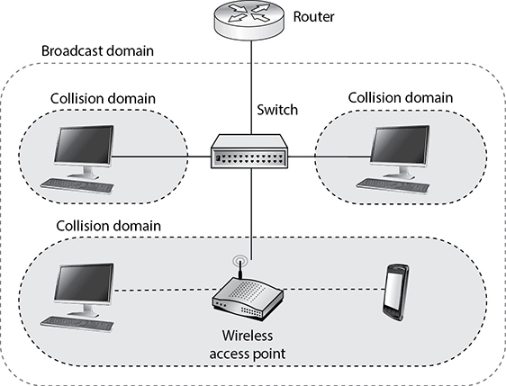
Figure 11-12 Collision domains within one broadcast domain
EXAM TIP
Broadcast domains are sets of computing nodes that all receive a layer 2 broadcast frame. These are normally all nodes that are interconnected, with no routers in between them. Collision domains are sets of computing nodes that may produce collisions when they transmit data. These are normally nodes connected by hubs, repeaters, or wireless access points.
Another benefit of restricting and controlling broadcast and collision domains is that it makes sniffing the network and obtaining useful information more difficult for an intruder as he traverses the network. A useful tactic for attackers is to install a Trojan horse that sets up a network sniffer on the compromised computer. The sniffer is usually configured to look for a specific type of information, such as usernames and passwords. If broadcast and collision domains are in effect, the compromised system will have access only to the broadcast and collision traffic within its specific subnet or broadcast domain. The compromised system will not be able to listen to traffic on other broadcast and collision domains, and this can greatly reduce the amount of traffic and information available to an attacker.
Polling
The third type of media-sharing method, besides CSMA and token passing, is polling. Polling is a medium access control mechanism that relies on a primary station that periodically polls all others in its collision domain. Each polled device responds by stating whether or not it has anything to send. In some implementations, the secondary stations (devices) can also let the primary station know how much data they want to send, where it’s going to, and how urgent it is. After polling all secondary stations, the primary station allocates the channel according to whatever policy it follows. It could, for example, prioritize traffic from one station, or type, or evenly divide the channel among all stations that asked to access it.
The main thing to remember about polling MAC is that each device needs to wait until the primary station completes a poll and then tells that device how much of the channel it can use. Only then can a secondary station transmit data. This approach is very uncommon in LANs, though it is used in some wireless networks. Polling is much more common in wide area networks.
Layer 2 Protocols
Now that we’ve discussed LAN topologies and MAC mechanisms, let’s look at how these are implemented in reality. For the CISSP exam, you should know three layer 2 protocols: Ethernet, Token Ring, and FDDI. In reality, you are almost certainly to only use Ethernet and its wireless cousin Wi-Fi. Token Ring and FDDI are exceptionally rare in LANs, though FDDI is still used as the backbone of metropolitan area networks (MANs).
Ethernet
Ethernet is a set of technologies that enables several devices to communicate on the same network. Ethernet usually uses a bus or star topology. If a linear bus topology is used, all devices connect to one cable. If a star topology is used, each device is connected to a cable that is connected to a centralized device, such as a switch. Ethernet was developed in the 1970s, became commercially available in 1980, and was officially defined through the IEEE 802.3 standard.
Ethernet has seen quite an evolution in its short history, from purely coaxial cable installations that worked at 10 Mbps to mostly twisted-pair cable that works at speeds of 100 Mbps, 1,000 Mbps (1 Gbps), and up to 40 Gbps.
Ethernet is defined by the following characteristics:
• Contention-based technology (all resources use the same shared communication medium)
• Uses broadcast and collision domains
• Uses the CSMA access method
• Supports full-duplex communication
• Can use coaxial, twisted-pair, or fiber-optic cabling types, but most commonly uses UTP cables
• Is defined by the IEEE 802.3 family of standards
Ethernet addresses how computers share a common network and how they deal with collisions, data integrity, communication mechanisms, and transmission controls. These are the common characteristics of Ethernet, but Ethernet does vary in the type of cabling schemes and transfer rates it can supply. Several types of Ethernet implementations are available, as outlined in Table 11-2.

Table 11-2 Ethernet Implementation Types
10Base-T was considered heaven-sent when it first arrived on the networking scene, but soon many users were demanding more speed and power. It is now considered a legacy standard and is very rarely seen in organizational networks. There are ongoing efforts, however, to develop variants of this obsolete standard for use in automotive and IoT applications. Today, the most widely deployed type of Ethernet in organizational networks is 1000Base-T.
Token Ring
The Token Ring technology was originally developed by IBM and then defined by the IEEE 802.5 standard. At first, Token Ring technology had the ability to transmit data at 4 Mbps. Later, it was improved to transmit at 16 Mbps. It uses a token-passing technology with a star-configured topology. The ring part of the name pertains to how the signals travel, which is in a logical ring. Each computer is connected to a central hub, called a Multistation Access Unit (MAU). Physically, the topology can be a star, but the signals and transmissions are passed in a logical ring.
As previously described, token-passing technology is one in which a device cannot put data on the network wire without having possession of a token, a control frame that travels in a logical circle and is “picked up” when a system needs to communicate. This is different from Ethernet, in which all the devices attempt to communicate at the same time. This is why Ethernet is referred to as a “chatty protocol” and has collisions. Token Ring does not endure collisions, since only one system can communicate at a time, but this also means communication takes place more slowly compared to Ethernet.
Token Ring employs a couple of mechanisms to deal with problems that can occur on this type of network. The active monitor mechanism removes frames that are continuously circulating on the network. This can occur if a computer locks up or is taken offline for one reason or another and cannot properly receive a token destined for it. With the beaconing mechanism, if a computer detects a problem with the network, it sends a beacon frame. This frame generates a failure domain, which is between the computer that issued the beacon and its neighbor downstream. The computers and devices within this failure domain will attempt to reconfigure certain settings to try to work around the detected fault. Figure 11-13 depicts a Token Ring network in a physical star configuration. Token Ring networks were popular in the 1980s and 1990s, and although some are still around, Ethernet is much more popular.
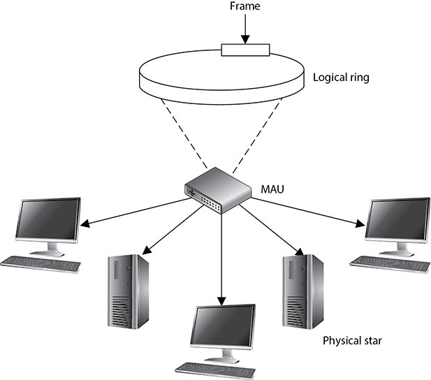
Figure 11-13 A Token Ring network
FDDI
Fiber Distributed Data Interface (FDDI) technology, developed by the American National Standards Institute (ANSI), is a high-speed, token-passing, medium access technology. FDDI has a data transmission speed of up to 100 Mbps and is usually used as a backbone network using fiber-optic cabling. FDDI also provides fault tolerance by offering a second counter-rotating fiber ring. The primary ring has data traveling clockwise and is used for regular data transmission. The second ring transmits data in a counterclockwise fashion and is invoked only if the primary ring goes down. Sensors watch the primary ring and, if it goes down, invoke a ring wrap so the data will be diverted to the second ring. Each node on the FDDI network has relays that are connected to both rings, so if a break in the ring occurs, the two rings can be joined.
When FDDI is used as a backbone network, it usually connects several different networks, as shown in Figure 11-14.
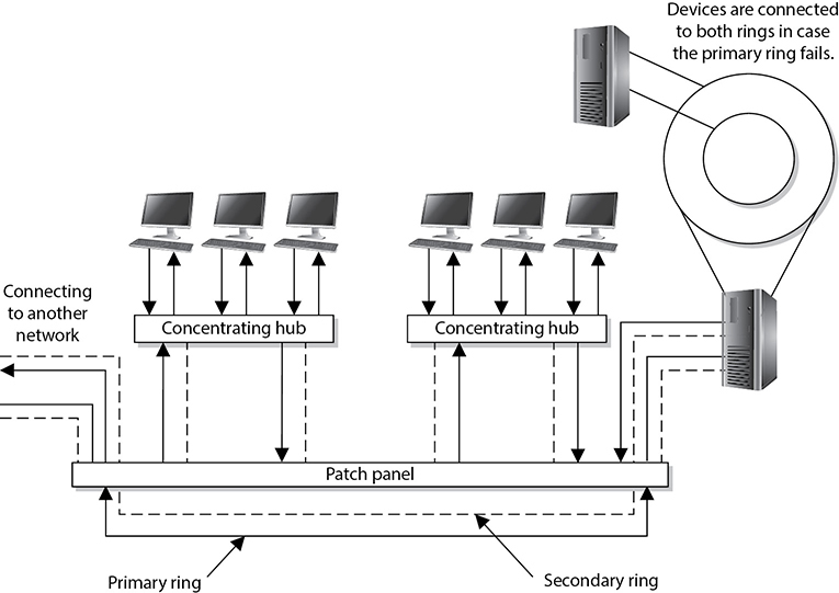
Figure 11-14 FDDI rings can be used as backbones to connect different LANs.
Before Fast Ethernet and Gigabit Ethernet hit the market, FDDI was used mainly as campus and service provider backbones. Because FDDI can be employed for distances up to 100 kilometers, it was often used in MANs. The benefit of FDDI is that it can work over long distances and at high speeds with minimal interference. It enables several tokens to be present on the ring at the same time, causing more communication to take place simultaneously, and it provides predictable delays that help connected networks and devices know what to expect and when.
NOTE
A version of FDDI, Copper Distributed Data Interface (CDDI), can work over UTP cabling.
Devices that connect to FDDI rings fall into one of the following categories:
• Single-attachment station (SAS) Attaches to only one ring (the primary) through a concentrator
• Dual-attachment station (DAS) Has two ports and each port provides a connection for both the primary and the secondary rings
• Single-attached concentrator (SAC) Concentrator that connects an SAS device to the primary ring
• Dual-attached concentrator (DAC) Concentrator that connects DAS, SAS, and SAC devices to both rings
The different FDDI device types are illustrated in Figure 11-15.

Figure 11-15 FDDI device types
NOTE
Ring topologies are considered deterministic, meaning that the rate of the traffic flow can be predicted. Since traffic can only flow if a token is in place, the maximum time that a node will have to wait to receive traffic can be determined. This can be beneficial for time-sensitive applications.
Layer 2 Network Protocol Summary
Table 11-3 sums up the important characteristics of the technologies described in the preceding sections.
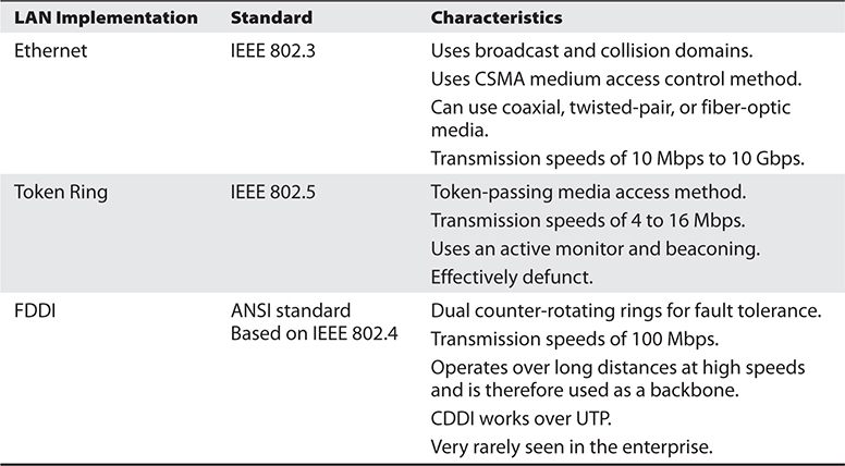
Table 11-3 LAN Media Access Methods
Transmission Methods
A packet may need to be sent to only one workstation, to a set of workstations, or to all workstations on a particular subnet. If a packet needs to go from the source computer to one particular system, a unicast transmission method is used. If the packet needs to go to a specific group of systems, the sending system uses the multicast method. If a system wants all computers on its subnet to receive a message, it uses the broadcast method.
Unicast is pretty simple because it has a source address and a destination address. The data goes from point A to point B, it is a one-to-one transmission, and everyone is happy. Multicast is a bit different in that it is a one-to-many transmission. Multicasting enables one computer to send data to a selective group of computers. A good example of multicasting is tuning into a radio station on a computer. Some computers have software that enables the user to determine whether she wants to listen to rock, Latin, or a talk radio station, for example. Once the user selects one of these genres, the software must tell the NIC driver to pick up not only packets addressed to its specific MAC address but also packets that contain a specific multicast address.
The difference between broadcast and multicast is that in a broadcast one-to-all transmission, everyone gets the data, whereas in a multicast, only certain nodes receive the data. So how does a server three states away multicast to one particular computer on a specific network and no other networks in between? Suppose a user tunes in to her favorite Internet radio station. An application running on her computer (say, a web browser) has to tell her local router she wants to get frames with this particular multicast address passed her way. The local router must tell the router upstream, and this process continues so each router between the source and destination knows where to pass this multicast data. This ensures that the user can get her rock music without other networks being bothered with this extra data.
IPv4 multicast protocols use a Class D address (224.0.0.0 to 239.255.255.255), which is a special address space reserved for multicasting. IPv6 multicast addresses start with eight 1’s (that is, 1111 1111). Multicasting can be used to send out information; multimedia data; and even real-time video, music, and voice clips.
Internet Group Management Protocol (IGMP) is used to report multicast group memberships to routers. When a user chooses to accept multicast traffic, she becomes a member of a particular multicast group. IGMP is the mechanism that allows her computer to inform the local routers that she is part of this group and to send traffic with a specific multicast address to her system. IGMP can be used for online streaming video and gaming activities. The protocol allows for efficient use of the necessary resources when supporting these types of applications.
Like most protocols, IGMP has gone through a few different versions, each improving upon the earlier one. In version 1, multicast agents periodically send queries to systems on the network they are responsible for and update their databases, indicating which system belongs to which group membership. Version 2 provides more granular query types and allows a system to signal to the agent when it wants to leave a group. Version 3 allows the systems to specify the sources it wants to receive multicast traffic from. Each version is backward-compatible because versions 1 and 2 are still in use in legacy equipment.
NOTE
The previous statements are true pertaining to IPv4. IPv6 is more than just an upgrade to the original IP protocol; it functions differently in many respects, including how it handles multicasting, which has caused many interoperability issues and delay in its full deployment.
Layer 2 Security Standards
As frames pass from one network device to another device, attackers could sniff the data; modify the headers; redirect the traffic; spoof traffic; carry out man-in-the-middle attacks, DoS attacks, and replay attacks; and indulge in other malicious activities. It has become necessary to secure network traffic at the frame level, which is layer 2 of the OSI model.
802.1AE is the IEEE MAC Security (MACSec) standard, which defines a security infrastructure to provide data confidentiality, data integrity, and data origin authentication. Where a VPN connection provides protection at the higher networking layers, MACSec provides hop-by-hop protection at layer 2, as shown in Figure 11-16.

Figure 11-16 MACSec provides layer 2 frame protection.
MACSec integrates security protection into wired Ethernet networks to secure LAN-based traffic. Only authenticated and trusted devices on the network can communicate with each other. Unauthorized devices are prevented from communicating via the network, which helps prevent attackers from installing rogue devices and redirecting traffic between nodes in an unauthorized manner. When a frame arrives at a device that is configured with MACSec, the MACSec Security Entity (SecY) decrypts the frame if necessary and computes an integrity check value (ICV) on the frame and compares it with the ICV that was sent with the frame. If the ICVs match, the device processes the frame. If they do not match, the device handles the frame according to a preconfigured policy, such as discarding it.
The IEEE 802.1AR standard specifies unique per-device identifiers (DevID) and the management and cryptographic binding of a device (router, switch, access point) to its identifiers. A verifiable unique device identity allows establishment of the trustworthiness of devices, and thus facilitates secure device provisioning.
As a security administrator you really only want devices that are allowed on your network to be plugged into your network. But how do you properly and uniquely identify devices? The manufacturer’s serial number is not available for a protocol to review. MAC addresses, hostnames, and IP addresses are easily spoofed. 802.1AR defines a globally unique per-device secure identifier cryptographically bound to the device through the use of public cryptography and digital certificates. These unique hardware-based credentials can be used with the Extensible Authentication Protocol-Transport Layer Security (EAP-TLS) authentication framework. Each device that is compliant with IEEE 802.1AR comes with a single built-in initial secure device identity (iDevID). The iDevID is an instance of the general concept of a DevID, which is intended to be used with authentication protocols such as EAP, which is supported by IEEE 802.1X.
So 802.1AR provides a unique ID for a device. 802.1AE provides data encryption, integrity, and origin authentication functionality. 802.1AF carries out key agreement functions for the session keys used for data encryption. Each of these standards provides specific parameters to work within an 802.1X EAP-TLS framework, as shown in Figure 11-17.
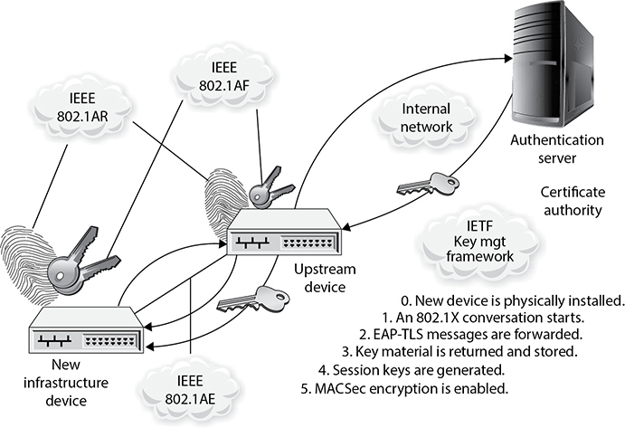
Figure 11-17 Layer 2 security protocols
As Figure 11-17 shows, when a new device is installed on the network, it cannot just start communicating with other devices, receive an IP address from a Dynamic Host Configuration Protocol (DHCP) server, resolve names with the Domain Name System (DNS) server, and so on. The device cannot carry out any network activity until it is authorized to do so. So 802.1X port authentication kicks in, which means that only authentication data is allowed to travel from the new device to the authenticating server. The authentication data is the digital certificate and hardware identity associated with that device (802.1AR), which is processed by EAP-TLS. Once the device is authenticated, usually by a Remote Authentication Dial-In User Server (RADIUS) server, encryption keying material is negotiated and agreed upon between surrounding network devices. Once the keying material is installed, then data encryption and frame integrity checking can take place (802.1AE) as traffic goes from one network device to the next.
These IEEE standards are new and evolving and at different levels of implementation by various vendors. One way the unique hardware identity and cryptographic material are embedded in new network devices is through the use of a Trusted Platform Module (TPM; described in Chapter 9).
Internet Protocol Networking
Unless your network consists of only a few devices, isolated from the Internet (and what good is that?), you will need to move from layer 2 into layer 3 and above to do anything meaningful. Recall that the data link layer is concerned with exchanging data between devices that are directly connected to each other (in other words, in the same collision domain). Beyond that, we need layer 3 (network) and 4 (transport) protocols, such as TCP/IP.
The Transmission Control Protocol/Internet Protocol (TCP/IP) is a suite of protocols that governs the way data travels from one device to another. IP is a network layer protocol and provides datagram routing services. IP’s main task is to support internetwork addressing and packet routing. It is a connectionless protocol that envelops data passed to it from the transport layer. The IP protocol addresses the datagram with the source and destination IP addresses. The protocols within the TCP/IP suite work together to break down the data passed from the application layer into pieces that can be moved along a network. They work with other protocols to transmit the data to the destination computer and then reassemble the data back into a form that the application layer can understand and process.
Two main protocols work at the transport layer: TCP and UDP. TCP is a reliable and connection-oriented protocol, which means it ensures packets are delivered to the destination computer. If a packet is lost during transmission, TCP has the ability to identify this issue and resend the lost or corrupted packet. TCP also supports packet sequencing (to ensure each and every packet was received), flow and congestion control, and error detection and correction. UDP, on the other hand, is a best-effort and connectionless protocol. It has neither packet sequencing nor flow and congestion control, and the destination does not acknowledge every packet it receives.
TCP
TCP is referred to as a connection-oriented protocol because before any user data is actually sent, handshaking takes place between the two systems that want to communicate. Once the handshaking completes successfully, a virtual connection is set up between the two systems. UDP is considered a connectionless protocol because it does not go through these steps. Instead, UDP sends out messages without first contacting the destination computer and does not know if the packets were received properly or dropped. Figure 11-18 shows the difference between a connection-oriented protocol and a connectionless protocol.
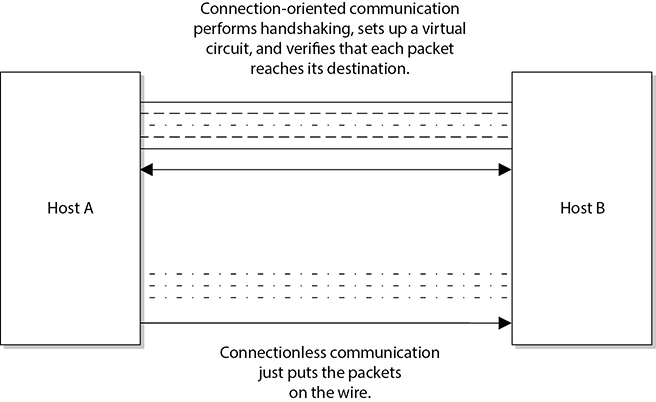
Figure 11-18 Connection-oriented protocol vs. connectionless protocol functionality
UDP and TCP sit together on the transport layer, and developers can choose which to use when developing applications. Many times, TCP is the transport protocol of choice because it provides reliability and ensures the packets are delivered. TCP provides a full-duplex, reliable communication mechanism, and if any packets are lost or damaged, they are re-sent; however, TCP requires a lot of system overhead compared to UDP.
If developers know that data being dropped during transmission is not detrimental to the application, they may choose to use UDP because it is faster and requires fewer resources. For example, UDP is a better choice than TCP when a server sends status information to all listening nodes on the network. A node will not be negatively affected if, by some chance, it did not receive this status information, because the information will be re-sent every 60 seconds.
UDP and TCP are transport protocols that applications use to get their data across a network. They both use ports to communicate with upper OSI layers and to keep track of various conversations that take place simultaneously. The ports are also the mechanism used to identify how other computers access services. When a TCP or UDP message is formed, source and destination ports are contained within the header information along with the source and destination IP addresses. The combination of protocol (TCP or UDP), port, and IP address makes up a socket, and is how packets know where to go (by the address) and how to communicate with the right service or protocol on the other computer (by the port number). The IP address acts as the doorway to a computer, and the port acts as the doorway to the actual protocol or service. To communicate properly, the packet needs to know these doors. Figure 11-19 shows how packets communicate with applications and services through ports.

Figure 11-19 The packet can communicate with upper-layer protocols and services through a port.
The difference between TCP and UDP can also be seen in the message formats. Because TCP offers more services than UDP, it must contain much more information within its packet header format, as shown in Figure 11-20. Table 11-4 lists the major differences between TCP and UDP.
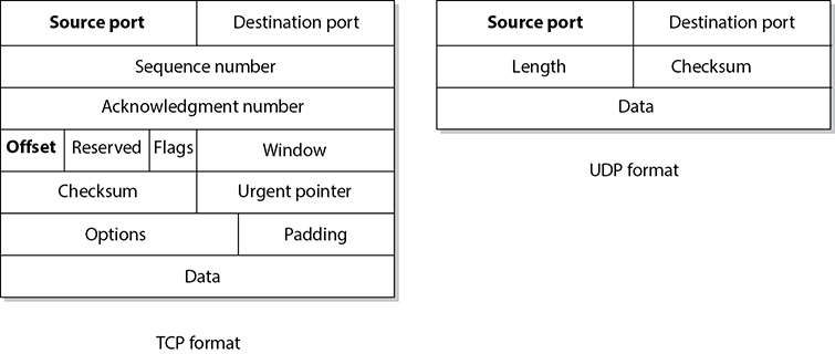
Figure 11-20 TCP carries a lot more information within its segment because it offers more services than UDP.
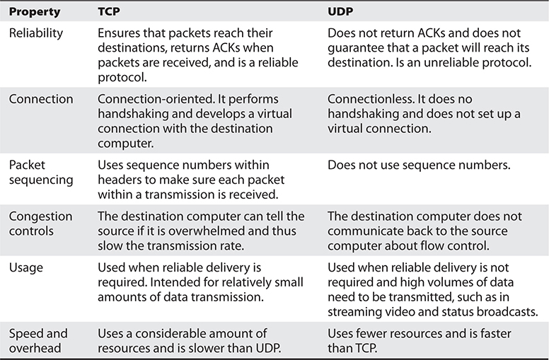
Table 11-4 Major Differences Between TCP and UDP
TCP Handshake
TCP must set up a virtual connection between two hosts before any data is sent. This means the two hosts must agree on certain parameters, data flow, windowing, error detection, and options. These issues are negotiated during the handshaking phase, as shown in Figure 11-21.

Figure 11-21 The TCP three-way handshake
The host that initiates communication sends a synchronization (SYN) packet to the receiver. The receiver acknowledges this request by sending a SYN/ACK packet. This packet translates into, “I have received your request and am ready to communicate with you.” The sending host acknowledges this with an acknowledgment (ACK) packet, which translates into, “I received your acknowledgment. Let’s start transmitting our data.” This completes the handshaking phase, after which a virtual connection is set up, and actual data can now be passed. The connection that has been set up at this point is considered full duplex, which means transmission in both directions is possible using the same transmission line.
If an attacker sends a target system SYN packets with a spoofed address, then the victim system replies to the spoofed address with SYN/ACK packets. Each time the victim system receives one of these SYN packets, it sets aside resources to manage the new connection. If the attacker floods the victim system with SYN packets, eventually the victim system allocates all of its available TCP connection resources and can no longer process new requests. This is a type of DoS attack that is referred to as a SYN flood. To thwart this type of attack you can use a number of mitigations, the most common of which are described in the Internet Engineering Task Force’s (IETF) Request for Comments (RFC) 4987. One of the most effective techniques described in RFC 4987 is the use of SYN caches, which delays the allocation of a socket until the handshake is completed.
Another attack vector we need to understand is TCP sequence numbers. One of the values that is agreed upon during a TCP handshake between two systems is the sequence numbers that will be inserted into the packet headers. Once the sequence number is agreed upon, if a receiving system receives a packet from the sending system that does not have this predetermined value, it disregards the packet. This means that an attacker cannot just spoof the address of a sending system to fool a receiving system; the attacker has to spoof the sender’s address and use the correct sequence number values. If an attacker can correctly predict the TCP sequence numbers that two systems will use, then she can create packets containing those numbers and fool the receiving system into thinking that the packets are coming from the authorized sending system. She can then take over the TCP connection between the two systems, which is referred to as TCP session hijacking.
Data Structures
As stated earlier, the message is formed and passed to the application layer from a program and sent down through the protocol stack. Each protocol at each layer adds its own information to the message to create a PDU and passes it down to the next layer. This activity is referred to as encapsulation. As the message is passed down the stack, it goes through a sort of evolution, and each stage has a specific name that indicates what is taking place. When an application formats data to be transmitted over the network, the PDU is called a message or data. The message is sent to the transport layer, where TCP does its magic on it. The PDU is now a segment. The segment is sent to the network layer. The network layer adds routing and addressing, and now the PDU is called a packet. The network layer passes off the packet to the data link layer, which frames the packet with a header and a trailer, and now it is called a frame. Figure 11-22 illustrates these stages.
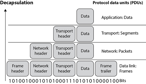
Figure 11-22 Data goes through its own evolutionary stages as it passes through the layers within the network stack.
EXAM TIP
If the message is being transmitted over TCP, it is referred to as a “segment.” If it is being transmitted over UDP, it is referred to as a “datagram.”
Sometimes when an author refers to a segment, she is specifying the stage in which the data is located within the protocol stack. If the literature is describing routers, which work at the network layer, the author might use the word “packet” because the data at this layer has routing and addressing information attached. If an author is describing network traffic and flow control, she might use the word “frame” because all data actually ends up in the frame format before it is put on the network wire. The important thing here is that you understand the various steps a data package goes through when it moves up and down the protocol stack.
IP Addressing
Each node on a network must have a unique IP address. Today, the most commonly used version of IP is IP version 4 (IPv4), which is used by roughly 70 percent of Internet hosts as we write these words. IP version 6 (IPv6), which was created in part to address the shortage of IPv4 addresses (IPv6 also has many security features built into it that are not part of IPv4), is steadily gaining ground, however. IPv6 is covered later in this chapter.
IPv4 uses 32 bits for its addresses, whereas IPv6 uses 128 bits; thus, IPv6 provides more possible addresses with which to work. Each address has a host portion and a network portion, and the addresses are grouped into classes and then into subnets. The subnet mask of the address differentiates the groups of addresses that define the subnets of a network. IPv4 address classes are listed in Table 11-5.

Table 11-5 IPv4 Addressing
For any given IP network within an organization, all nodes connected to the network can have different host addresses but a common network address. The host address identifies every individual node, whereas the network address is the identity of the network all the nodes are connected to; therefore, it is the same for each one of them. Any traffic meant for nodes on this network will be sent to the prescribed network address.
A subnet is created from the host portion of an IP address to designate a “sub” network. This allows us to further break the host portion of the address into two or more logical groupings, as shown in Figure 11-23. A network can be logically partitioned to reduce administration headaches, increase traffic performance, and potentially strengthen security. As an analogy, let’s say you work at Toddlers R Us and you are responsible for babysitting 100 toddlers. If you kept all 100 toddlers in one room, you would probably end up crazy. To better manage these kids, you could break them up into groups. The three-year-olds go in the yellow room, the four-year-olds go in the green room, and the five-year-olds go in the blue room. This is what a network administrator would do—break up and separate computer nodes to be able to better control them. Instead of putting them into physical rooms, the administrator puts them into logical rooms (subnets).
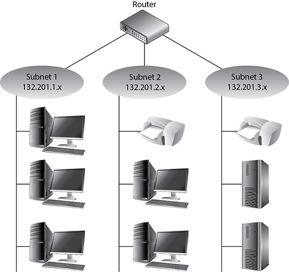
Figure 11-23 Subnets create logical partitions.
To continue with our analogy, when you put your toddlers in different rooms, you would have physical barriers that separate them—walls. Network subnetting is not physical; it is logical. This means you would not have physical walls separating your individual subnets, so how do you keep them separate? This is where subnet masks come into play. A subnet mask defines smaller networks inside a larger network, just like individual rooms are defined within a building.
Subnetting allows larger IP address ranges to be divided into smaller, logical, and more tangible network segments. Consider an organization with several divisions, such as IT, Accounting, HR, and so on. Creating subnets for each division breaks the networks into logical partitions that route traffic directly to recipients without dispersing data all over the network. This drastically reduces the traffic load across the network, reducing the possibility of network congestion and excessive broadcast packets in the network. Implementing network security policies is also much more effective across logically categorized subnets with a demarcated perimeter, as compared to a large, cluttered, and complex network.
Subnetting is particularly beneficial in keeping down routing table sizes because external routers can directly send data to the actual network segment without having to worry about the internal architecture of that network and getting the data to individual hosts. This job can be handled by the internal routers, which can determine the individual hosts in a subnetted environment and save the external routers the hassle of analyzing all 32 bits of an IP address and just look at the “masked” bits.
 TIP
TIP
You should not have to calculate any subnets for the CISSP exam, but for a better understanding of how this stuff works under the hood, check out the article “IP Tutorial: Subnet Mask and Subnetting” at https://www.lifewire.com/internet-protocol-tutorial-subnets-818378 (keep in mind that URLs are subject to change from time to time).
If the traditional subnet masks are used, they are referred to as classful or classical IP addresses. If an organization needs to create subnets that do not follow these traditional sizes, then it would use classless IP addresses. This just means a different subnet mask would be used to define the network and host portions of the addresses. After it became clear that available IP addresses were running out as more individuals and corporations participated on the Internet, classless interdomain routing (CIDR) was created. A Class B address range is usually too large for most organizations, and a Class C address range is too small, so CIDR provides the flexibility to increase or decrease the class sizes as necessary. CIDR is the method to specify more flexible IP address classes. CIDR is also referred to as supernetting.
TIP
To better understand CIDR, a good resource is “IP Classless Addressing: Classless Inter-Domain Routing (CIDR)/“Supernetting”: www.tcpipguide.com/free/t_IPClasslessAddressingClasslessInterDomainRoutingCI.htm.
Although each node has an IP address, people usually refer to their hostname rather than their IP address. Hostnames, such as www.mheducation.com, are easier for humans to remember than IP addresses, such as 198.105.254.228. However, the use of these two nomenclatures requires mapping between the hostnames and IP addresses because the computer understands only the numbering scheme. This process is addressed in the “Domain Name Service” section later in this chapter.
NOTE
IP provides addressing, packet fragmentation, and packet timeouts. To ensure that packets do not continually traverse a network forever, IP provides a Time to Live (TTL) value that is decremented every time the packet passes through a router.
IPv6
IPv6, also called IP next generation (IPng), not only has a larger address space than IPv4 to support more IP addresses; it has some capabilities that IPv4 does not and it accomplishes some of the same tasks differently. All of the specifics of the new functions within IPv6 are beyond the scope of this book, but we will look at a few of them, because IPv6 is the way of the future. IPv6 allows for scoped addresses, which enables an administrator to restrict specific addresses for specific servers or file and print sharing, for example. IPv6 has Internet Protocol Security (IPSec) integrated into the protocol stack, which provides end-to-end secure transmission and authentication. IPv6 has more flexibility and routing capabilities and allows for Quality of Service (QoS) priority values to be assigned to time-sensitive transmissions. The protocol offers autoconfiguration, which makes administration much easier, and it does not require network address translation (NAT) to extend its address space.
NAT was developed because IPv4 addresses were running out. Although the NAT technology is extremely useful, it has caused a lot of overhead and transmission problems because it breaks the client/server model that many applications use today. One reason the industry did not jump on the IPv6 bandwagon when it came out years ago is that NAT was developed, which reduced the speed at which IP addresses were being depleted. Although the conversion rate from IPv4 to IPv6 is slow in some parts of the world and the implementation process is quite complicated, the industry is making the shift because of all the benefits that IPv6 brings to the table.
NOTE
NAT is covered in the “Network Address Translation” section later in this chapter.
The IPv6 specification, as outlined in RFC 8200, lays out the differences and benefits of IPv6 over IPv4. A few of the differences are as follows:
• IPv6 increases the IP address size from 32 bits to 128 bits to support more levels of addressing hierarchy, a much greater number of addressable nodes, and simpler autoconfiguration of addresses.
• The scalability of multicast routing is improved by adding a “scope” field to multicast addresses. Also, a new type of address called an anycast address is defined, which is used to send a packet to any one of a group of nodes.
• Some IPv4 header fields have been dropped or made optional to reduce the common-case processing cost of packet handling and to limit the bandwidth cost of the IPv6 header. This is illustrated in Figure 11-24.
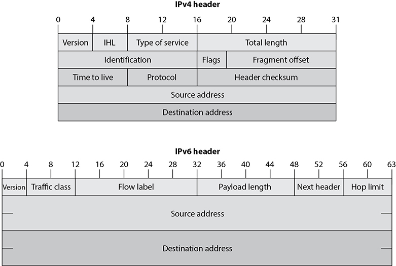
Figure 11-24 IPv4 vs. IPv6 headers
• Changes in the way IP header options are encoded allow for more efficient forwarding, less stringent limits on the length of options, and greater flexibility for introducing new options in the future.
• A new capability is added to enable the labeling of packets belonging to particular traffic “flows” for which the sender requests special handling, such as nondefault QoS or “real-time” service.
• Extensions to support authentication, data integrity, and (optional) data confidentiality are also specified for IPv6.
IPv4 limits packets to 65,535 bytes of payload, and IPv6 extends this size to 4,294,967,295 bytes. These larger packets are referred to as jumbograms and improve performance over high-MTU links. Currently most of the world still uses IPv4, but IPv6 is being deployed more rapidly. This means that there are “pockets” of networks using IPv4 and “pockets” of networks using IPv6 that still need to communicate. This communication takes place through different tunneling techniques, which either encapsulate IPv6 packets within IPv4 packets or carry out automated address translations. Automatic tunneling is a technique where the routing infrastructure automatically determines the tunnel endpoints so that protocol tunneling can take place without preconfiguration. In the 6to4 tunneling method, the tunnel endpoints are determined by using a well-known IPv4 anycast address on the remote side and embedding IPv4 address data within IPv6 addresses on the local side. Teredo is another automatic tunneling technique that uses UDP encapsulation so that NAT address translations are not affected. Intra-Site Automatic Tunnel Addressing Protocol (ISATAP) treats the IPv4 network as a virtual IPv6 local link, with mappings from each IPv4 address to a link-local IPv6 address.
The 6to4 and Teredo are intersite tunneling mechanisms, and ISATAP is an intrasite mechanism. So the first two are used for connectivity between different networks, and ISATAP is used for connectivity of systems within a specific network. Notice in Figure 11-25 that 6to4 and Teredo are used on the Internet and ISATAP is used within an intranet.

Figure 11-25 Various IPv4 to IPv6 tunneling techniques
While many of these automatic tunneling techniques reduce administration overhead, because network administrators do not have to configure each and every system and network device with two different IP addresses, there are security risks that need to be understood. Many times users and network administrators do not know that automatic tunneling capabilities are enabled, and thus they do not ensure that these different tunnels are secured and/or are being monitored. If you are an administrator of a network and have intrusion detection systems (IDSs), intrusion prevention systems (IPSs), and firewalls that are only configured to monitor and restrict IPv4 traffic, then all IPv6 traffic could be traversing your network insecurely. Attackers use these protocol tunnels and misconfigurations to get past these types of security devices so that malicious activities can take place unnoticed. If you are a user and have a host-based firewall that only understands IPv4 and your operating system has a dual IPv4/IPv6 networking stack, traffic could be bypassing your firewall without being monitored and logged. The use of Teredo can actually open ports in NAT devices that allow for unintended traffic in and out of a network.
It is critical that people who are responsible for configuring and maintaining systems and networks understand the differences between IPv4 and IPv6 and how the various tunneling mechanisms work so that all vulnerabilities are identified and properly addressed. Products and software may need to be updated to address both traffic types, proxies may need to be deployed to manage traffic communication securely, IPv6 should be disabled if not needed, and security appliances need to be configured to monitor all traffic types.
Address Resolution Protocol
On a TCP/IP network, each computer and network device requires a unique IP address and a unique physical hardware address. Each NIC has a unique 48-bit physical address that is programmed by the manufacturer into the ROM chips on the card. The physical address is also referred to as the Media Access Control (MAC) address. The network layer works with and understands IP addresses, and the data link layer works with and understands physical MAC addresses. So, how do these two types of addresses work together while operating at different layers?
NOTE
A MAC address is unique because the first 24 bits represent the manufacturer code and the last 24 bits represent the unique serial number assigned by the manufacturer.
When data comes from the application layer, it goes to the transport layer for sequence numbers, session establishment, and streaming. The data is then passed to the network layer, where routing information is added to each packet and the source and destination IP addresses are attached to the data bundle. Then this goes to the data link layer, which must find the MAC address and add it to the header portion of the frame. When a frame hits the wire, it only knows what MAC address it is heading toward. At this lower layer of the OSI model, the mechanisms do not even understand IP addresses. So if a computer cannot resolve the IP address passed down from the network layer to the corresponding MAC address, it cannot communicate with that destination computer.
NOTE
A frame is data that is fully encapsulated, with all of the necessary headers and trailers.
MAC and IP addresses must be properly mapped so they can be correctly resolved. This happens through the Address Resolution Protocol (ARP). When the data link layer receives a frame, the network layer has already attached the destination IP address to it, but the data link layer cannot understand the IP address and thus invokes ARP for help. ARP broadcasts a frame requesting the MAC address that corresponds with the destination IP address. Each computer on the broadcast domain receives this frame, and all but the computer that has the requested IP address ignore it. The computer that has the destination IP address responds with its MAC address. Now ARP knows what hardware address corresponds with that specific IP address. The data link layer takes the frame, adds the hardware address to it, and passes it on to the physical layer, which enables the frame to hit the wire and go to the destination computer. ARP maps the hardware address and associated IP address and stores this mapping in its table for a predefined amount of time. This caching is done so that when another frame destined for the same IP address needs to hit the wire, ARP does not need to broadcast its request again. It just looks in its table for this information.
Sometimes attackers alter a system’s ARP table so it contains incorrect information. This is called ARP table cache poisoning. The attacker’s goal is to receive packets intended for another computer. This is a type of masquerading attack. For example, let’s say that Bob’s computer has an IP address of 10.0.0.1 and a MAC address of bb:bb:bb:bb:bb:bb, Alice’s computer has an IP address of 10.0.0.7 and a MAC address of aa:aa:aa:aa:aa:aa, and an attacker has an IP address of 10.0.0.3 and a MAC address of cc:cc:cc:cc:cc:cc, as shown in Figure 11-26. Suppose Bob wants to send a message to Alice. The message is encapsulated at the IP layer with information including Alice’s IP address and then handed off to the data link layer. If this is the first message for Alice’s computer, the data link process on Bob’s computer has no way of knowing her MAC address, so it crafts an ARP query that (literally) says “Who has 10.0.0.7?” This ARP frame is broadcast to the network, where it is received by both Alice’s computer and the attacker’s computer. Both respond claiming to be the rightful owners of that IP address. What does Bob’s computer do when faced with multiple different responses? The answer in most cases is that it uses the most recent response. If the attacker wants to ensure that Bob’s ARP table remains poisoned, then he will have to keep pumping out bogus ARP replies.

Figure 11-26 ARP poisoning attack
So ARP is critical for a system to communicate, but it can be manipulated to allow traffic to be sent to unintended systems. ARP is a rudimentary protocol and does not have any security measures built in to protect itself from these types of attacks. Networks should have IDS sensors monitoring for this type of malicious activity so that administrators can be alerted if it is underway. This is not difficult to detect, since, as already noted, the attacker will have to constantly (or at least frequently) transmit bogus ARP replies.
Dynamic Host Configuration Protocol
A computer can receive its IP addresses in a few different ways when it first boots up. If it has a statically assigned address, nothing needs to happen. It already has the configuration settings it needs to communicate and work on the intended network. If a computer depends upon a DHCP server to assign it the correct IP address, it boots up and makes a request to the DHCP server. The DHCP server assigns the IP address, and everyone is happy.
DHCP is a UDP-based protocol that allows servers to assign IP addresses to network clients in real time. Unlike static IP addresses, where IP addresses are manually configured, the DHCP server automatically checks for available IP addresses and correspondingly assigns an IP address to the client. This eliminates the possibility of IP address conflicts that occur if two systems are assigned identical IP addresses, which could cause loss of service. On the whole, DHCP considerably reduces the effort involved in managing large-scale IP networks.
The DHCP server assigns IP addresses in real time from a specified range when a client connects to the network; this is different from static addresses, where each system is individually assigned a specific IP address when coming online. In a standard DHCP-based network, the client computer broadcasts a DHCPDISCOVER message on the network in search of the DHCP server. Once the respective DHCP server receives the DHCPDISCOVER request, the server responds with a DHCPOFFER packet, offering the client an IP address. The server assigns the IP address based on the subject of the availability of that IP address and in compliance with its network administration policies. The DHCPOFFER packet that the server responds with contains the assigned IP address information and configuration settings for client-side services.
Once the client receives the settings sent by the server through the DHCPOFFER packet, it responds to the server with a DHCPREQUEST packet confirming its acceptance of the allotted settings. The server now acknowledges with a DHCPACK packet, which includes the validity period (lease) for the allocated parameters.
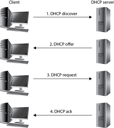
So as shown in Figure 11-27, the DHCP client yells out to the network, “Who can help me get an address?” The DHCP server responds with an offer: “Here is an address and the parameters that go with it.” The client accepts this gracious offer with the DHCPREQUEST message, and the server acknowledges this message. Now the client can start interacting with other devices on the network and the user can surf the Web and check her e-mail.
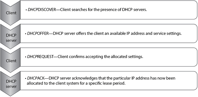
Figure 11-27 The four stages of the Discover, Offer, Request, and Acknowledgment (D-O-R-A) process
Unfortunately, both the client and server segments of DHCP are vulnerable to falsified identity. On the client end, attackers can masquerade their systems to appear as valid network clients. This enables rogue systems to become a part of an organization’s network and potentially infiltrate other systems on the network. An attacker may create an unauthorized DHCP server on the network and start responding to clients searching for a DHCP server. A DHCP server controlled by an attacker can compromise client system configurations, carry out man-in-the-middle attacks, route traffic to unauthorized networks, and a lot more, with the end result of jeopardizing the entire network.
An effective method to shield networks from unauthenticated DHCP clients is through the use of DHCP snooping on network switches. DHCP snooping ensures that DHCP servers can assign IP addresses to only selected systems, identified by their MAC addresses. Also, advanced network switches have the capability to direct clients toward legitimate DHCP servers to get IP addresses and restrict rogue systems from becoming DHCP servers on the network.
Diskless workstations do not have a full operating system but have just enough code to know how to boot up and broadcast for an IP address, and they may have a pointer to the server that holds the operating system. The diskless workstation knows its hardware address, so it broadcasts this information so that a listening server can assign it the correct IP address. As with ARP, Reverse Address Resolution Protocol (RARP) frames go to all systems on the subnet, but only the RARP server responds. Once the RARP server receives this request, it looks in its table to see which IP address matches the broadcast hardware address. The server then sends a message that contains its IP address back to the requesting computer. The system now has an IP address and can function on the network.
The Bootstrap Protocol (BOOTP) was created after RARP to enhance the functionality that RARP provides for diskless workstations. The diskless workstation can receive its IP address, the name server address for future name resolutions, and the default gateway address from the BOOTP server. BOOTP usually provides more functionality to diskless workstations than does RARP.
Internet Control Message Protocol
The Internet Control Message Protocol (ICMP) is basically IP’s “messenger boy.” ICMP delivers status messages, reports errors, replies to certain requests, and reports routing information and is used to test connectivity and troubleshoot problems on IP networks.
The most commonly understood use of ICMP is its use by the ping utility. When a person wants to test connectivity to another system, he may ping it, which sends out ICMP Echo Request frames. The replies on his screen that are returned to the ping utility are called ICMP Echo Reply frames and are responding to the Echo Request frames. If a reply is not returned within a predefined time period, the ping utility sends more Echo Request frames. If there is still no reply, ping indicates the host is unreachable.
ICMP also indicates when problems occur with a specific route on the network and tells surrounding routers about better routes to take based on the health and congestion of the various pathways. Routers use ICMP to send messages in response to packets that could not be delivered. The router selects the proper ICMP response and sends it back to the requesting host, indicating that problems were encountered with the transmission request.
ICMP is used by other connectionless protocols, not just IP, because connectionless protocols do not have any way of detecting and reacting to transmission errors, as do connection-oriented protocols. In these instances, the connectionless protocol may use ICMP to send error messages back to the sending system to indicate networking problems.
As you can see in Table 11-6, ICMP is used for many different networking purposes. This table lists the various messages that can be sent to systems and devices through ICMP.

Table 11-6 ICMP Message Types
Attacks Using ICMP
ICMP was developed to send status messages, not to hold or transmit user data. But someone figured out how to insert some data inside of an ICMP packet, which can be used to communicate to an already compromised system. This technique is called ICMP tunneling, and is an older, but still effective, client/server approach that can be used by hackers to set up and maintain covert communication channels to compromised systems. The attacker would target a computer and install the server portion of the tunneling software. This server portion would “listen” on a port, which is the back door an attacker can use to access the system. To gain access and open a remote shell to this computer, an attacker would send commands inside of ICMP packets. This is usually successful because many routers and firewalls are configured to allow ICMP traffic to come and go out of the network, based on the assumption that this is safe because ICMP was developed to not hold any data or a payload.
Just as any tool that can be used for good can also be used for evil, attackers commonly use ICMP to redirect traffic. The redirected traffic can go to the attacker’s dedicated system, or it can go into a “black hole.” Routers use ICMP messages to update each other on network link status. An attacker could send a bogus ICMP message with incorrect information, which could cause the routers to divert network traffic to where the attacker indicates it should go.
ICMP is also used as the core protocol for a network tool called Traceroute. Traceroute is used to diagnose network connections, but since it gathers a lot of important network statistics, attackers use the tool to map out a victim’s network. This is similar to a burglar “casing the joint,” meaning that the more the attacker learns about the environment, the easier it can be for her to exploit some critical targets. So while the Traceroute tool is a valid networking program, a security administrator might configure the IDS sensors to monitor for extensive use of this tool because it could indicate that an attacker is attempting to map out the network’s architecture.
The countermeasures to these types of attacks are to use firewall rules that only allow the necessary ICMP packets into the network and the use of an IDS or IPS to watch for suspicious activities. Host-based protection (host firewalls and host IDS) can also be installed and configured to identify this type of suspicious behavior.
Simple Network Management Protocol
The Simple Network Management Protocol (SNMP) was released to the networking world in 1988 to help with the growing demand of managing network IP devices. Organizations use many types of products that use SNMP to view the status of their network, traffic flows, and the hosts within the network. Since these tasks are commonly carried out using graphical user interface (GUI)–based applications, many people do not have a full understanding of how the protocol actually works. The protocol is important to understand because it can provide a wealth of information to attackers, and you should understand the amount of information that is available to the ones who wish to do you harm, how they actually access this data, and what can be done with it.
The two main components within SNMP are managers and agents. The manager is the server portion, which polls different devices to check status information. The server component also receives trap messages from agents and provides a centralized place to hold all network-wide information. The agent is a piece of software that runs on a network device, which is commonly integrated into the operating system. The agent has a list of objects that it is to keep track of, which is held in a database-like structure called the Management Information Base (MIB). A MIB is a logical grouping of managed objects that contain data used for specific management tasks and status checks.
When the SNMP manager component polls the individual agent installed on a specific device, the agent pulls the data it has collected from the MIB and sends it to the manager. Figure 11-28 illustrates how data pulled from different devices is located in one centralized location (SNMP manager). This allows the network administrator to have a holistic view of the network and the devices that make up that network.
NOTE
The trap operation allows the agent to inform the manager of an event, instead of having to wait to be polled. For example, if an interface on a router goes down, an agent can send a trap message to the manager. This is the only way an agent can communicate with the manager without first being polled.
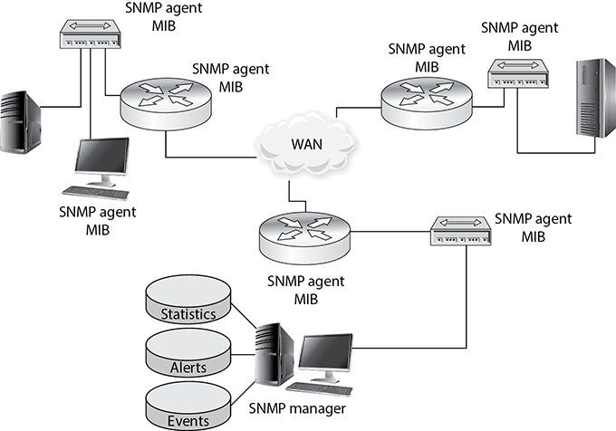
Figure 11-28 Agents provide the manager with SNMP data.
It might be necessary to restrict which managers can request information of an agent, so communities were developed to establish a trust between specific agents and managers. A community string is basically a password a manager uses to request data from the agent, and there are two main community strings with different levels of access: read-only and read-write. As the names imply, the read-only community string allows a manager to read data held within a device’s MIB, and the read-write string allows a manager to read the data and modify it. If an attacker can uncover the read-write string, she could change values held within the MIB, which could reconfigure the device.
Since the community string is a password, it should be hard to guess and be protected. It should contain mixed-case alphanumeric strings that are not dictionary words. This practice is not always the case in many networks. The usual default read-only community string is “public” and the read-write string is “private.” Many organizations do not change these, so anyone who can connect to port 161 can read the status information of a device and potentially reconfigure it. Different vendors may put in their own default community string values, but organizations may still not take the necessary steps to change them. Attackers usually have lists of default vendor community string values, so they can be easily discovered and used against networks.
To make matters worse, the community strings are sent in cleartext in SNMP v1 and v2, so even if a company does the right thing by changing the default values, the strings are still easily accessible to any attacker with a sniffer. If you absolutely have to use v1 or v2 (and you really shouldn’t because they are obsolete), make sure that different network segments use different community strings, so that if one string is compromised an attacker cannot gain access to all the devices in the network. The SNMP ports (161 and 162) should not be open to untrusted networks, like the Internet, and if needed they should be filtered to ensure only authorized individuals can connect to them. If these ports need to be available to an untrusted network, configure the router or firewall to only allow UDP traffic to come and go from preapproved network-management stations. While versions 1 and 2 of this protocol send the community string values in cleartext, version 3 has cryptographic functionality, which provides encryption, message integrity, and authentication security. So, SNMP v3 should be implemented for more granular protection.
If the proper countermeasures are not put into place, then an attacker can gain access to a wealth of device-oriented data that can be used in her follow-up attacks. The following are just some data sets held within MIB SNMP objects that attackers would be interested in:
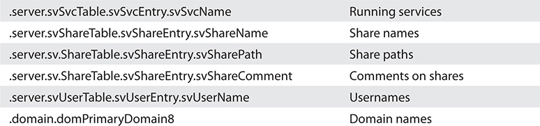
Gathering this type of data allows an attacker to map out the target network and enumerate the nodes that make up the network.
As with all tools, SNMP is used for good purposes (network management) and for bad purposes (target mapping, device reconfiguration). We need to understand both sides of all tools available to us.
Domain Name Service
Imagine how hard it would be to use the Internet if we had to remember actual specific IP addresses to get to various websites. The Domain Name Service (DNS) is a method of resolving hostnames to IP addresses so names can be used instead of IP addresses within networked environments.
The first iteration of the Internet was made up of about 100 computers (versus over 22 billion now), and a list was kept that mapped every system’s hostname to its IP address. This list was kept on an FTP server so everyone could access it. It did not take long for the task of maintaining this list to become overwhelming, and the computing community looked to automate it.
When a user types a uniform resource locator (URL) into his web browser, the URL is made up of words or letters that are in a sequence that makes sense to that user, such as www.google.com. However, these words are only for humans—computers work with IP addresses. So after the user enters this URL and presses ENTER, behind the scenes his computer is actually being directed to a DNS server that will resolve this URL, or hostname, into an IP address that the computer understands. Once the hostname has been resolved into an IP address, the computer knows how to get to the web server holding the requested web page.
Many organizations have their own DNS servers to resolve their internal hostnames. These organizations usually also use the DNS servers at their Internet service providers (ISPs) to resolve hostnames on the Internet. An internal DNS server can be used to resolve hostnames on the entire LAN, but usually more than one DNS server is used so the load can be split up and so redundancy and fault tolerance are in place.
Within DNS servers, DNS namespaces are split up administratively into zones. One zone may contain all hostnames for the marketing and accounting departments, and another zone may contain hostnames for the administration, research, and legal departments. The DNS server that holds the files for one of these zones is said to be the authoritative name server for that particular zone. A zone may contain one or more domains, and the DNS server holding those host records is the authoritative name server for those domains.
The DNS server contains records that map hostnames to IP addresses, which are referred to as resource records. When a user’s computer needs to resolve a hostname to an IP address, it looks to its networking settings to find its DNS server. The computer then sends a request, containing the hostname, to the DNS server for resolution. The DNS server looks at its resource records and finds the record with this particular hostname, retrieves the address, and replies to the computer with the corresponding IP address.
It is recommended that a primary and a secondary DNS server cover each zone. The primary DNS server contains the actual resource records for a zone, and the secondary DNS server contains copies of those records. Users can use the secondary DNS server to resolve names, which takes a load off of the primary server. If the primary server goes down for any reason or is taken offline, users can still use the secondary server for name resolution. Having both a primary DNS server and a secondary DNS server provides fault tolerance and redundancy to ensure users can continue to work if something happens to one of these servers.
The primary and secondary DNS servers synchronize their information through a zone transfer. After changes take place to the primary DNS server, those changes must be replicated to the secondary DNS server. It is important to configure the DNS server to allow zone transfers to take place only between the specific servers. For years now, attackers have been carrying out unauthorized zone transfers to gather very useful network information from victims’ DNS servers.
An unauthorized zone transfer provides the attacker with information on almost every system within the network, including the hostname and IP address of each system, system alias names, public key infrastructure (PKI) server, DHCP server, DNS servers, and so on. This allows an attacker to carry out very targeted attacks on specific systems. If you were the attacker and you had a new exploit for DHCP software, now you would know the IP address of the company’s DHCP server and could send your attack parameters directly to that system. Also, since the zone transfer can provide data on all of the systems in the network, the attacker can map out the network. He knows what subnets are being used, which systems are in each subnet, and where the critical network systems reside. This is analogous to you allowing a burglar into your house with the freedom of identifying where you keep your jewels, expensive stereo equipment, piggy bank, and keys to your car, which will allow him to more easily steal these items when you are on vacation. Unauthorized zone transfers can take place if the DNS servers are not properly configured to restrict this type of activity.
Internet DNS and Domains
Networks on the Internet are connected in a hierarchical structure, as are the different DNS servers, as shown in Figure 11-29. While performing routing tasks, if a router does not know the necessary path to the requested destination, that router passes the packet up to a router above it. The router above it knows about all the routers below it. This router has a broader view of the routing that takes place on the Internet and has a better chance of getting the packet to the correct destination. This holds true with DNS servers also. If one DNS server does not know which DNS server holds the necessary resource record to resolve a hostname, it can pass the request up to a DNS server above it.
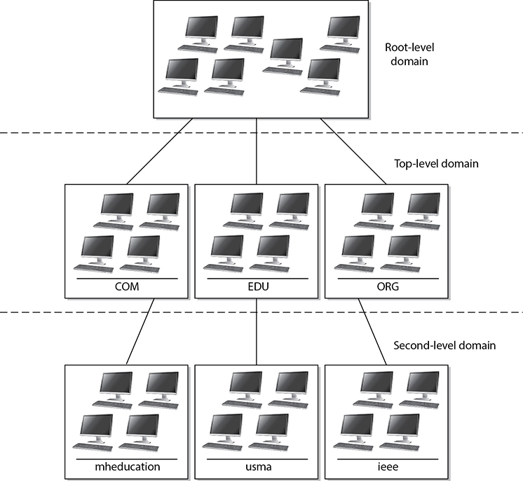
Figure 11-29 The DNS naming hierarchy is similar to the routing hierarchy on the Internet.
The naming scheme of the Internet resembles an inverted tree with the root servers at the top. Lower branches of this tree are divided into top-level domains, with second-level domains under each. The most common top-level domains are as follows:
• COM Commercial
• EDU Education
• MIL U.S. military organization
• INT International treaty organization
• GOV Government
• ORG Organizational
• NET Networks
So how do all of these DNS servers play together in the Internet playground? When a user types in a URL to access a website that sells computer books, for example, his computer asks its local DNS server if it can resolve this hostname to an IP address. If the primary DNS server cannot resolve the hostname, it must query a higher-level DNS server, ultimately ending at an authoritative DNS server for the specified domain. Because this website is most likely not on the corporate network, the local LAN DNS server will not usually know the necessary IP address of that website. The DNS server does not reject the user’s request, but rather passes it on to another DNS server on the Internet. The request for this hostname resolution continues through different DNS servers until it reaches one that knows the IP address. The requested host’s IP information is reported back to the user’s computer. The user’s computer then attempts to access the website using the IP address, and soon the user is buying computer books, happy as a clam.
DNS server and hostname resolution is extremely important in corporate networking and Internet use. Without it, users would have to remember and type in the IP address for each website and individual system instead of the name. That would be a mess.
Your computer has a DNS resolver, which is responsible for sending out requests to DNS servers for host IP address information. If your system did not have this resolver, when you type in www.google.com in your browser, you would not get to this website because your system does not actually know what www.google.com means. When you type in this URL, your system’s resolver has the IP address of a DNS server it is supposed to send its hostname-to-IP address request to. Your resolver can send out a nonrecursive query or a recursive query to the DNS server. A nonrecursive query means that the request just goes to that specified DNS server and either the answer is returned to the resolver or an error is returned. A recursive query means that the request can be passed on from one DNS server to another one until the DNS server with the correct information is identified.
In the following illustration, you can follow the succession of requests that commonly takes place. Your system’s resolver first checks to see if it already has the necessary hostname-to-IP address mapping cached or if it is in a local HOSTS file. If the necessary information is not found, the resolver sends the request to the local DNS server. If the local DNS server does not have the information, it sends the request to a different DNS server.

The HOSTS file resides on the local computer and can contain static hostname-to-IP address mapping information. If you do not want your system to query a DNS server, you can add the necessary data in the HOSTS file, and your system will check its contents before reaching out to a DNS server. HOSTS files are like two-edged swords: on the one hand they offer a degree of security by ensuring that certain hosts resolve to specific IP addresses, but on the other hand they are attractive targets for attackers who want to redirect your traffic to specific hosts. The key, as always, is to carefully analyze and mitigate the risks.
DNS Threats
As stated earlier, not every DNS server knows the IP address of every hostname it is asked to resolve. When a request for a hostname-to-IP address mapping arrives at a DNS server (server A), the server reviews its resource records to see if it has the necessary information to fulfill this request. If the server does not have a resource record for this hostname, it forwards the request to another DNS server (server B), which in turn reviews its resource records and, if it has the mapping information, sends the information back to server A. Server A caches this hostname-to-IP address mapping in its memory (in case another client requests it) and sends the information on to the requesting client.
With the preceding information in mind, consider a sample scenario. Andy the attacker wants to make sure that any time one of his competitor’s customers tries to visit the competitor’s website, the customer is instead pointed to Andy’s website. Therefore, Andy installs a tool that listens for requests that leave DNS server A asking other DNS servers if they know how to map the competitor’s hostname to its IP address. Once Andy sees that server A sends out a request to server B to resolve the competitor’s hostname, Andy quickly sends a message to server A indicating that the competitor’s hostname resolves to Andy’s website’s IP address. Server A’s software accepts the first response it gets, so server A caches this incorrect mapping information and sends it on to the requesting client. Now when the client tries to reach Andy’s competitor’s website, she is instead pointed to Andy’s website. This will happen subsequently to any user who uses server A to resolve the competitor’s hostname to an IP address because this information is cached on server A.
Previous vulnerabilities that have allowed this type of activity to take place have been addressed, but this type of attack is still taking place because when server A receives a response to its request, it does not authenticate the sender.
Mitigating DNS threats consists of numerous measures, the most important of which is the use of stronger authentication mechanisms such as the DNSSEC (DNS security, which is part of many current implementations of DNS server software). DNSSEC implements PKI and digital signatures, which allows DNS servers to validate the origin of a message to ensure that it is not spoofed and potentially malicious. If DNSSEC were enabled on server A, then server A would, upon receiving a response, validate the digital signature on the message before accepting the information to make sure that the response is from an authorized DNS server. So even if an attacker sends a message to a DNS server, the DNS server would discard it because the message would not contain a valid digital signature. DNSSEC allows DNS servers to send and receive authorized messages between themselves and thwarts the attacker’s goal of poisoning a DNS cache table.
This sounds simple enough, but for DNSSEC to be rolled out properly, all of the DNS servers on the Internet would have to participate in a PKI to be able to validate digital signatures. The implementation of Internet-wide PKIs simultaneously and seamlessly has proved to be difficult.
Despite the fact that DNSSEC requires more resources than the traditional DNS, more and more organizations globally are opting to use DNSSEC. As of this writing, 91 percent of the top-level domains implement DNSSEC. However, across the entire Internet, barely 3 percent of domains have implemented it. So we are getting there, slowly but surely.
Now let’s discuss another (indirectly related) predicament in securing DNS traffic—manipulation of the HOSTS file, a technique frequently used by malware. The HOSTS file is used by the operating system to map hostnames to IP addresses as described before. The HOSTS file is a plaintext file located in the %systemroot%system32driversetc folder in Windows, in /etc/hosts in Unix/Linux systems, and in /private/etc/hosts in macOS. The HOSTS file simply consists of a list of IP addresses with their corresponding hostnames.
Depending on its configuration, the computer refers to the HOSTS file before issuing a DNS request to a DNS server. Most operating systems give preference to details of IP addresses returned by the HOSTS file rather than querying the DNS server because the HOSTS file is generally under the direct control of the local system administrator.
As covered previously, in the early days of the Internet and prior to the adoption of DNS, HOSTS files were the primary source of determining a host’s network addresses from its hostname. With the increase in the number of hosts connected to the Internet, maintaining HOSTS files became next to impossible and ultimately led to the creation of DNS.
Due to the important role of HOSTS files, they are frequently targeted by malware to propagate across systems connected on a local network. Once a malicious program takes over the HOSTS file, it can divert traffic from its intended destination to websites hosting malicious content, for example. A common example of HOSTS file manipulation carried out by malware involves blocking users from visiting antivirus update websites. This is usually done by mapping target hostnames to the loopback interface IP address 127.0.0.1. The most effective technique for preventing HOSTS file intrusions is to set it as a read-only file and implement a host-based IDS that watches for critical file modification attempts.
Attackers don’t always have to go through all this trouble to divert traffic to rogue destinations. They can also use some very simple techniques that are surprisingly effective in routing naive users to unintended destinations. The most common approach is known as URL hiding. Hypertext Markup Language (HTML) documents and e-mail messages allow users to attach or embed hyperlinks in any given text, such as the “Click Here” links you commonly see in e-mail messages or web pages. Attackers misuse hyperlinks to deceive unsuspecting users into clicking rogue links.
Let’s say a malicious attacker creates an unsuspicious text, www.good.site, but embeds the link to an abusive website, www.bad.site. People are likely to click the www.good.site link without knowing that they are actually being taken to the bad site. In addition, attackers also use character encoding to obscure web addresses that may arouse user suspicion.
Network Address Translation
When computers need to communicate with each other, they must use the same type of addressing scheme so everyone understands how to find and talk to one another. The Internet uses the IP address scheme as discussed earlier in the chapter, and any computer or network that wants to communicate with other users on the network must conform to this scheme; otherwise, that computer will sit in a virtual room with only itself to talk to. However, IP addresses have become scarce (until the full adoption of IPv6) and expensive. So some smart people came up with network address translation (NAT), which enables a network that does not follow the Internet’s addressing scheme to communicate over the Internet.
Private IP addresses have been reserved for internal LAN address use, as outlined in RFC 1918. These addresses can be used within the boundaries of an organization, but they cannot be used on the Internet because they will not be properly routed. NAT enables an organization to use these private addresses and still be able to communicate transparently with computers on the Internet.
The following lists current private IP address ranges:
• 10.0.0.0–10.255.255.255 Class A networks
• 172.16.0.0–172.31.255.255 Class B networks
• 192.168.0.0–192.168.255.255 Class C networks
NAT is a gateway that lies between a network and the Internet (or another network) that performs transparent routing and address translation. Because IP addresses were depleting fast, IPv6 was developed in 1999, and was intended to be the long-term fix to the address shortage problem. NAT was developed as the short-term fix to enable more organizations to participate on the Internet. However, to date, IPv6 is slow in acceptance and implementation, while NAT has caught on like wildfire. Many firewall vendors have implemented NAT into their products, and it has been found that NAT actually provides a great security benefit. When attackers want to hack a network, they first do what they can to learn all about the network and its topology, services, and addresses. Attackers cannot easily find out an organization’s address scheme and its topology when NAT is in place, because NAT acts like a large nightclub bouncer by standing in front of the network and hiding the true IP scheme.
NAT hides internal addresses by centralizing them on one device, and any frames that leave that network have only the source address of that device, not of the actual internal computer that sends the message. So when a message comes from an internal computer with the address of 10.10.10.2, for example, the message is stopped at the device running NAT software, which happens to have the IP address of 1.2.3.4. NAT changes the header of the packet from the internal address, 10.10.10.2, to the IP address of the NAT device, 1.2.3.4. When a computer on the Internet replies to this message, it replies to the address 1.2.3.4. The NAT device changes the header on this reply message to 10.10.10.2 and puts it on the wire for the internal user to receive.
Three basic types of NAT implementations can be used:
• Static mapping The NAT software has a pool of public IP addresses configured. Each private address is statically mapped to a specific public address. So computer A always receives the public address x, computer B always receives the public address y, and so on. This is generally used for servers that need to keep the same public address at all times.
• Dynamic mapping The NAT software has a pool of IP addresses, but instead of statically mapping a public address to a specific private address, it works on a first-come, first-served basis. So if Bob needs to communicate over the Internet, his system makes a request to the NAT server. The NAT server takes the first IP address on the list and maps it to Bob’s private address. The balancing act is to estimate how many computers will most likely need to communicate outside the internal network at one time. This estimate is the number of public addresses the organization purchases, instead of purchasing one public address for each computer.
• Port address translation (PAT) The organization owns and uses only one public IP address for all systems that need to communicate outside the internal network. How in the world could all computers use the exact same IP address? Good question. Here’s an example: The NAT device has an IP address of 127.50.41.3. When computer A needs to communicate with a system on the Internet, the NAT device documents this computer’s private address and source port number (10.10.44.3; port 43,887). The NAT device changes the IP address in the computer’s packet header to 127.50.41.3, with the source port 40,000. When computer B also needs to communicate with a system on the Internet, the NAT device documents the private address and source port number (10.10.44.15; port 23,398) and changes the header information to 127.50.41.3 with source port 40,001. So when a system responds to computer A, the packet first goes to the NAT device, which looks up the port number 40,000 and sees that it maps to computer A’s real information. So the NAT device changes the header information to address 10.10.44.3 and port 43,887 and sends it to computer A for processing. An organization can save a lot more money by using PAT because it needs to buy only a few public IP addresses, which are used by all systems in the network.
Most NAT implementations are stateful, meaning they keep track of a communication between the internal host and an external host until that session is ended. The NAT device needs to remember the internal IP address and port to send the reply messages back. This stateful characteristic is similar to stateful-inspection firewalls, but NAT does not perform scans on the incoming packets to look for malicious characteristics. Instead, NAT is a service usually performed on routers or gateway devices within an organization’s screened subnet.
Although NAT was developed to provide a quick fix for the depleting IP address problem, it has actually put the problem off for quite some time. The more organizations that implement private address schemes, the less likely IP addresses will become scarce. This has been helpful to NAT and the vendors that implement this technology, but it has put the acceptance and implementation of IPv6 much farther down the road.
Routing Protocols
Individual networks on the Internet are referred to as autonomous systems (ASs). These ASs are independently controlled by different service providers and organizations. An AS is made up of routers, which are administered by a single entity and use a common Interior Gateway Protocol (IGP) within the boundaries of the AS. The boundaries of these ASs are delineated by border routers. These routers connect to the border routers of other ASs and run interior and exterior routing protocols. Internal routers connect to other routers within the same AS and run interior routing protocols. So, in reality, the Internet is just a network made up of ASs and routing protocols.
NOTE
As an analogy, just as the world is made up of different countries, the Internet is made up of different ASs. Each AS has delineated boundaries just as countries do. Countries can have their own languages (e.g., Spanish, Arabic, Russian). Similarly, ASs have their own internal routing protocols. Countries that speak different languages need to have a way of communicating with each other, which could happen through interpreters. ASs need to have a standardized method of communicating and working together, which is where external routing protocols come into play.
The architecture of the Internet that supports these various ASs is created so that no entity that needs to connect to a specific AS has to know or understand the interior routing protocols that are being used. Instead, for ASs to communicate, they just have to be using the same exterior routing protocols (see Figure 11-30). As an analogy, suppose you want to deliver a package to a friend who lives in another state. You give the package to your brother, who is going to take a train to the edge of the state and hand it to the postal system at that junction. Thus, you know how your brother will arrive at the edge of the state—by train. You do not know how the postal system will then deliver your package to your friend’s house (truck, car, bus), but that is not your concern. It will get to its destination without your participation. Similarly, when one network communicates with another network, the first network puts the data packet (package) on an exterior protocol (train), and when the data packet gets to the border router (edge of the state), the data is transferred to whatever interior protocol is being used on the receiving network.
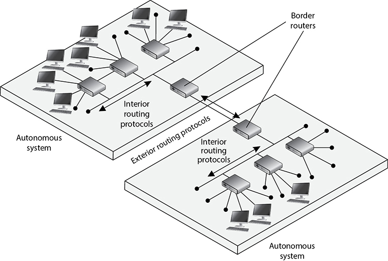
Figure 11-30 Autonomous systems
NOTE
Routing protocols are used by routers to identify a path between the source and destination systems.
Dynamic vs. Static
Routing protocols can be dynamic or static. A dynamic routing protocol can discover routes and build a routing table. Routers use these tables to make decisions on the best route for the packets they receive. A dynamic routing protocol can change the entries in the routing table based on changes that take place to the different routes. When a router that is using a dynamic routing protocol finds out that a route has gone down or is congested, it sends an update message to the other routers around it. The other routers use this information to update their routing table, with the goal of providing efficient routing functionality. A static routing protocol requires the administrator to manually configure the router’s routing table. If a link goes down or there is network congestion, the routers cannot tune themselves to use better routes.
NOTE
Route flapping refers to the constant changes in the availability of routes. Also, if a router does not receive an update that a link has gone down, the router will continue to forward packets to that route, which is referred to as a black hole.
Distance-Vector vs. Link-State
Two main types of routing protocols are used: distance-vector and link-state routing. Distance-vector routing protocols make their routing decisions based on the distance (or number of hops) and a vector (a direction). The protocol takes these variables and uses them with an algorithm to determine the best route for a packet. Link-state routing protocols build a more accurate routing table because they build a topology database of the network. These protocols look at more variables than just the number of hops between two destinations. They use packet size, link speed, delay, network load, and reliability as the variables in their algorithms to determine the best routes for packets to take.
So, a distance-vector routing protocol only looks at the number of hops between two destinations and considers each hop to be equal. A link-state routing protocol sees more pieces to the puzzle than just the number of hops, but understands the status of each of those hops and makes decisions based on these factors also. As you will see in the next section, RIP is an example of a distance-vector routing protocol, and OSPF is an example of a link-state routing protocol. OSPF is preferred and is used in large networks. RIP is still around but should only be used in smaller networks.
Interior Routing Protocols
Interior routing protocols (also known as Interior Gateway Protocols) route traffic within the same AS. Just like the process for flying from one airport to another is different if you travel domestically or internationally, routing protocols are designed differently depending on which side of the AS boundary they operate. De facto and proprietary interior protocols are being used today. The following are just a few of them:
• Routing Information Protocol RIP is a standard that outlines how routers exchange routing table data and is considered a distance-vector protocol, which means it calculates the shortest distance between the source and destination. It is considered a legacy protocol because of its slow performance and lack of functionality. It should only be used in small networks. RIP version 1 has no authentication, and RIP version 2 sends passwords in cleartext or hashed with MD5. RIPng is the third generation of this venerable protocol. It is very similar to version 2 but is designed for IPv6 routing.
• Open Shortest Path First OSPF uses link-state algorithms to send out routing table information. The use of these algorithms allows for smaller, more frequent routing table updates to take place. This provides a more stable network than RIP, but requires more memory and CPU resources to support this extra processing. OSPF allows for a hierarchical routing network that has a backbone link connecting all subnets together. OSPF has replaced RIP in many networks today. Authentication can take place with cleartext passwords or hashed passwords, or you can choose to configure no authentication on the routers using this protocol. The latest OSPF is version 3. Though it was designed to support IPv6, it also supports IPv4. Among the most important improvements is that OSPFv3 uses IPSec for authentication.
• Interior Gateway Routing Protocol IGRP is a distance-vector routing protocol that was developed by, and is proprietary to, Cisco Systems. Whereas RIP uses one criterion to find the best path between the source and destination, IGRP uses five criteria to make a “best route” decision. A network administrator can set weights on these different metrics so that the protocol works best in that specific environment.
• Enhanced Interior Gateway Routing Protocol EIGRP is a Cisco-proprietary and advanced distance-vector routing protocol. It allows for faster router table updates than its predecessor IGRP and minimizes routing instability, which can occur after topology changes. Routers exchange messages that contain information about bandwidth, delay, load, reliability, and MTU of the path to each destination as known by the advertising router. The latest version is 4.
• Virtual Router Redundancy Protocol VRRP is used in networks that require high availability where routers as points of failure cannot be tolerated. It is designed to increase the availability of the default gateway by advertising a “virtual router” as a default gateway. Two physical routers (primary and secondary) are mapped to one virtual router. If one of the physical routers fails, the other router takes over the workload.
• Intermediate System to Intermediate System IS-IS is a link-state protocol that allows each router to independently build a database of a network’s topology. Similar to the OSPF protocol, it computes the best path for traffic to travel. It is a classless and hierarchical routing protocol that is vendor neutral. Unlike other protocols (e.g., RIP and OSPF), IS-IS does not use IP addresses. Instead, it uses ISO addresses, which means that the protocol didn’t have to be redesigned to support IPv6.
NOTE
Although most routing protocols have authentication functionality, many routers do not have this functionality enabled.
Exterior Routing Protocols
The exterior routing protocols used by routers connecting different ASs are generically referred to as exterior gateway protocols (EGPs). The Border Gateway Protocol (BGP) enables routers on different ASs to share routing information to ensure effective and efficient routing between the different AS networks. BGP is commonly used by Internet service providers to route data from one location to the next on the Internet.
NOTE
There is an exterior routing protocol called Exterior Gateway Protocol, but it has been widely replaced by BGP, and now the term “exterior gateway protocol” and the acronym EGP are used to refer generically to a type of protocol rather than to specify the outdated protocol.
BGP uses a combination of link-state and distance-vector routing algorithms. It creates a network topology by using its link-state functionality and transmits updates on a periodic basis instead of continuously, which is how distance-vector protocols work. Network administrators can apply weights to the different variables used by link-state routing protocols when determining the best routes. These configurations are collectively called the routing policy.
Routing Protocol Attacks
Several types of attacks can take place on routers through their routing protocols. A majority of the attacks have the goal of misdirecting traffic through the use of spoofed ICMP messages. An attacker can masquerade as another router and submit routing table information to the victim router. After the victim router integrates this new information, it may be sending traffic to the wrong subnets or computers, or even to a nonexistent address (black hole). These attacks are successful mainly when routing protocol authentication is not enabled. When authentication is not required, a router can accept routing updates without knowing whether or not the sender is a legitimate router. An attacker could divert a company’s traffic to reveal confidential information or to just disrupt traffic, which would be considered a DoS attack.
Intranets and Extranets
Web technologies and their uses have exploded with functionality, capability, and popularity. Organizations set up internal websites for centralized business information such as employee phone numbers, policies, events, news, and operations instructions. Many organizations have also implemented web-based terminals that enable employees to perform their daily tasks, access centralized databases, make transactions, collaborate on projects, access global calendars, use videoconferencing tools and whiteboard applications, and obtain often-used technical or marketing data.
Web-based clients are different from workstations that log into a network and have their own desktop. Web-based clients limit a user’s ability to access the computer’s system files, resources, and hard drive space; access backend systems; and perform other tasks. The web-based client can be configured to provide a GUI with only the buttons, fields, and pages necessary for the users to perform tasks. This gives all users a standard universal interface with similar capabilities.
When an organization uses web-based technologies that are only available inside its networks, it is using an intranet, a “private” network. The organization has web servers and client machines using web browsers, and it uses the TCP/IP protocol suite. The web pages are written in HTML or XML (eXtensible Markup Language) and are accessed via HTTP.
Using web-based technologies has many pluses. They have been around for quite some time, they are easy to implement, no major interoperability issues occur, and with just the click of a link, a user can be taken to the location of the requested resource. Web-based technologies are not platform dependent, meaning all websites and pages may be maintained on various platforms and different flavors of client workstations can access them—they only need a web browser.
An extranet extends outside the bounds of the organization’s network to enable two or more organizations to share common information and resources. Business partners commonly set up extranets to accommodate business-to-business communication. An extranet enables business partners to work on projects together; share marketing information; communicate and work collaboratively on issues; post orders; and share catalogs, pricing structures, and information on upcoming events. Trading partners often use electronic data interchange (EDI), which provides structure and organization to electronic documents, orders, invoices, purchase orders, and a data flow. EDI has evolved into web-based technologies to provide easy access and easier methods of communication.
For many organizations, an extranet can create a weakness or hole in their security if the extranet is not implemented and maintained properly. Properly configured firewalls need to be in place to control who can use the extranet communication channels. Extranets used to be based mainly on dedicated transmission lines, which are more difficult for attackers to infiltrate, but today many extranets are set up over the Internet, which requires properly configured VPNs and security policies.
Metropolitan Area Networks
A metropolitan area network (MAN) is usually a backbone that connects LANs to each other and LANs to WANs, the Internet, and telecommunications and cable networks. A majority of today’s MANs are Synchronous Optical Networks (SONETs) or FDDI rings and Metro Ethernet provided by the telecommunications service providers. (FDDI technology was discussed earlier in the chapter.) The SONET and FDDI rings cover a large area, and businesses can connect to the rings via T1, fractional T1, and T3 lines. Figure 11-31 illustrates two companies connected via a SONET ring and the devices usually necessary to make this type of communication possible. This is a simplified example of a MAN. In reality, several businesses are usually connected to one ring.
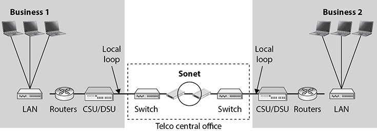
Figure 11-31 A MAN covers a large area and enables businesses to connect to each other, to the Internet, or to other WAN connections.
SONET is a standard for telecommunications transmissions over fiber-optic cables. Carriers and telephone companies have deployed SONET networks for North America, and if they follow the SONET standards properly, these various networks can intercommunicate with little difficulty. SONET is self-healing, meaning that if a break in the line occurs, it can use a backup redundant ring to ensure transmission continues. All SONET lines and rings are fully redundant. The redundant line waits in the wings in case anything happens to the primary ring.
SONET networks can transmit voice, video, and data over optical networks. Slower-speed SONET networks often feed into larger, faster SONET networks, as shown in Figure 11-32. This enables businesses in different cities and regions to communicate.
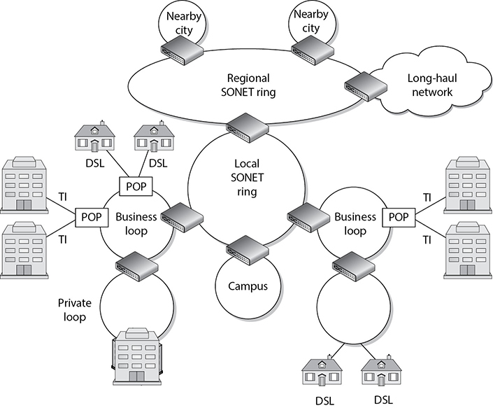
Figure 11-32 Smaller SONET rings connect to larger SONET rings to construct individual MANs.
MANs can be made up of wireless infrastructures, optical fiber, or Ethernet connections. Ethernet has evolved from just being a LAN technology to being used in MAN environments. Due to its prevalent use within organizations’ networks, Ethernet is easily extended and interfaced into MAN networks. A service provider commonly uses layer 2 and 3 switches to connect optical fibers, which can be constructed in a ring, star, or partial mesh topology.
Metro Ethernet
Ethernet has been around for many years and is embedded in almost every LAN. Ethernet LANs can connect to the previously mentioned MAN technologies, or they can be extended to cover a metropolitan area, which is called Metro Ethernet.
Ethernet on the MAN can be used as pure Ethernet or Ethernet integrated with other networking technologies, as in Multiprotocol Label Switching (MPLS). Pure Ethernet is less expensive but less reliable and scalable. MPLS-based deployments are more expensive but highly reliable and scalable, and are typically used by large service providers.
MAN architectures are commonly built upon three layers: access, aggregation/distribution, and core. The access layer provides services directly to the customers, typically at data rates of 10 Gbps or less. The aggregation layer provides routing for customer data, most of which passes on to the core layer, which operates at data rates of 100 Gbps or higher as illustrated in Figure 11-33.

Figure 11-33 MAN architecture
Access devices exist at a customer’s premises and connect the customer’s equipment to the service provider’s network. The service provider’s distribution network aggregates the traffic and sends it to the provider’s core network. From there, the traffic is moved to the next aggregation network that is closest to the destination. This is similar to how smaller highways are connected to larger interstates with on and off ramps that allow people to quickly travel from one location to a different one.
Wide Area Networks
LAN technologies provide communication capabilities over a small geographic area, whereas wide area network (WAN) technologies are used when communication needs to travel over a larger geographical area. LAN technologies encompass how a computer puts its data onto a network cable, the rules and protocols of how that data is formatted and transmitted, how errors are handled, and how the destination computer picks up this data from the cable. When a computer on one network needs to communicate with a network on the other side of the country or in a different country altogether, WAN technologies kick in.
The network must have some avenue to other networks, which is most likely a router that communicates with the organization’s service provider’s switches or telephone company facilities. Just as several types of technologies lie within the LAN arena, several technologies lie within the WAN arena. The following sections discuss the dedicated links that oftentimes connect LANs to WANs and the various technologies used in WANs.
Dedicated Links
A dedicated link is also called a leased line or point-to-point link. It is one single link that is pre-established for the purposes of WAN communications between two destinations. It is dedicated, meaning only the destination points can communicate with each other. This link is not shared by any other entities at any time. This was the main way organizations communicated in the past, because there were not as many choices available as there are today. Establishing a dedicated link is a good idea for two locations that will communicate often and require fast transmission and a specific bandwidth, but it is expensive compared to other possible technologies that enable several organizations to share the same bandwidth and also share the cost. This does not mean that dedicated lines are not in use; they definitely are used, but many other options are now available, including X.25, frame relay, and ATM technologies.
T-Carriers
T-carriers are dedicated lines that can carry voice and data information over trunk lines. They were developed by AT&T and were initially implemented in the early 1960s to support pulse-code modulation (PCM) voice transmission. This was first used to digitize the voice over a dedicated, point-to-point, high-capacity connection line. The most commonly used T-carriers are T1 lines and T3 lines. Both are digital circuits that multiplex several individual channels into a higher-speed channel.
These lines can have multiplex functionality through time-division multiplexing (TDM). What does this multiplexing stuff really mean? It means that each channel gets to use the path only during a specific time slot. It’s like having a time-share property on the beach; each co-owner gets to use it, but only one can do so at a time and can only remain for a fixed number of days. Consider a T1 line, which can multiplex up to 24 channels. If a company has a PBX connected to a T1 line, which in turn connects to the telephone company switching office, 24 calls can be chopped up and placed on the T1 line and transferred to the switching office. If this company did not use a T1 line, it would need 24 individual twisted pairs of wire to handle this many calls.
As shown in Figure 11-34, data is input into these 24 channels and transmitted. Each channel gets to insert up to 8 bits into its established time slot. Twenty-four of these 8-bit time slots make up a T1 frame. That does not sound like much information, but 8,000 frames are built per second. Because this happens so quickly, the receiving end does not notice a delay and does not know it is sharing its connection and bandwidth with up to 23 other devices.
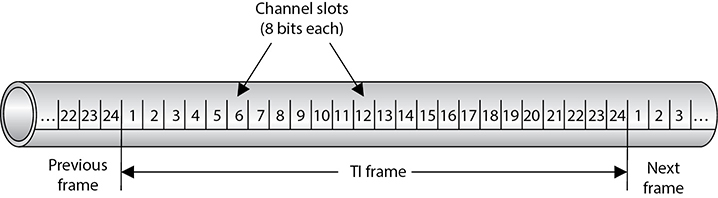
Figure 11-34 Multiplexing puts several phone calls, or data transmissions, on the same wire.
Originally, T1 and T3 lines were used by the carrier companies, but they have been replaced mainly with optical lines. Now T1 and T3 lines feed data into these powerful and super-fast optical lines. The T1 and T3 lines are leased to organizations and ISPs that need high-capacity transmission capability. Sometimes, T1 channels are split up between organizations that do not need the full bandwidth of 1.544 Mbps. These are called fractional T lines. The different carrier lines and their corresponding characteristics are listed in Table 11-7.
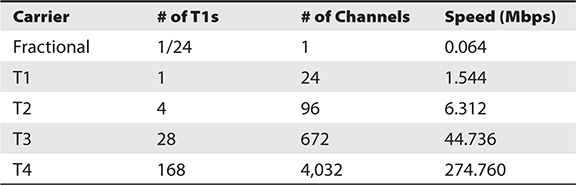
Table 11-7 A T-Carrier Hierarchy Summary Chart
As mentioned earlier, dedicated lines have their drawbacks. They are expensive and inflexible. If a company moves to another location, a T1 line cannot easily follow it. A dedicated line is expensive because organizations have to pay for a dedicated connection with a lot of bandwidth even when they do not use the bandwidth. Not many organizations require this level of bandwidth 24 hours a day. Instead, they may have data to send out here and there, but not continuously.
The cost of a dedicated line is determined by the distance to the destination. A T1 line run from one building to another building 2 miles away is much cheaper than a T1 line that covers 50 miles or a full state.
E-Carriers
E-carriers are similar to T-carrier telecommunication connections, where a single physical wire pair can be used to carry many simultaneous voice conversations by time-division multiplexing. Within this technology 30 channels interleave 8 bits of data in a frame. While the T-carrier and E-carrier technologies are similar, they are not interoperable. E-carriers are used by European countries. The E-carrier channels and associated rates are shown in Table 11-8.

Table 11-8 E-Carrier Characteristics
The most commonly used channels are E1 and E3 and fractional E-carrier lines.
Optical Carrier
High-speed fiber-optic connections are measured in optical carrier (OC) transmission rates. The transmission rates are defined by rate of the bit stream of the digital signal and are designated by an integer value of the multiple of the basic unit of rate. They are generically referred to as OCx, where x represents a multiplier of the basic OC-1 transmission rate, which is 51.84 Mbps. The carrier levels and speeds are shown in Table 11-9.

Table 11-9 OC Transmission Rates
Small and medium-sized organizations that require high-speed Internet connectivity may use OC-3 or OC-12 connections. Service providers that require much larger amounts of bandwidth may use one or more OC-48 connections. OC-192 and greater connections are commonly used for the Internet backbone, which connects the largest networks in the world together.
WAN Technologies
Several varieties of WAN technologies are available to organizations today. The information that an organization evaluates to decide which is the most appropriate WAN technology for it usually includes functionality, bandwidth demands, service level agreements, required equipment, cost, and what is available from service providers. The following sections go over some of the WAN technologies available today.
CSU/DSU
A channel service unit/data service unit (CSU/DSU) is required when digital equipment will be used to connect a LAN to a WAN. This connection can take place with T1 and T3 lines, as shown in Figure 11-35. A CSU/DSU is necessary because the signals and frames can vary between the LAN equipment and the WAN equipment used by service providers.
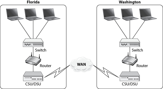
Figure 11-35 A CSU/DSU is required for digital equipment to communicate with telecommunications lines.
Here are some other types of multiplexing functionalities you should be aware of:
Statistical time-division multiplexing (STDM):
• Transmits several types of data simultaneously across a single transmission cable or line (such as a T1 or T3 line).
• Analyzes statistics related to the typical workload of each input device (printer, fax, computer) and determines in real time how much time each device should be allocated for data transmission.
Frequency-division multiplexing (FDM):
• An available wireless spectrum is used to move data.
• Available frequency band is divided into narrow frequency bands and used to have multiple parallel channels for data transfer.
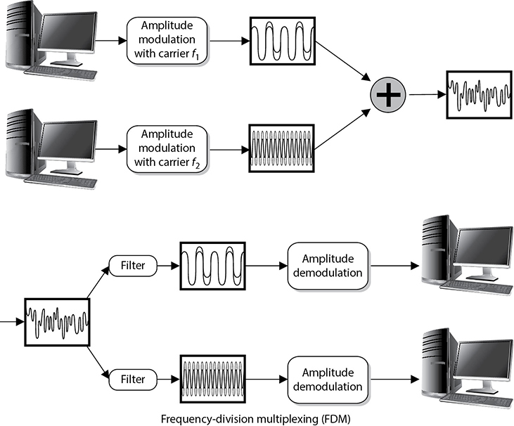
Wave-division multiplexing (WDM):
• Used in fiber-optic communication.
• Multiplexes a number of optical carrier signals onto a single optical fiber.
The DSU device converts digital signals from routers, switches, and multiplexers into signals that can be transmitted over the service provider’s digital lines. The DSU device ensures that the voltage levels are correct and that information is not lost during the conversion. The CSU connects the network directly to the service provider’s line. The CSU/DSU is not always a separate device and can be part of a networking device.
The CSU/DSU provides a digital interface for data terminal equipment (DTE), such as terminals, multiplexers, or routers, and an interface to the data circuit–terminating equipment (DCE) device, such as a carrier’s switch. The CSU/DSU basically works as a translator and, at times, as a line conditioner.
Switching
Dedicated links have one single path to traverse; thus, there is no complexity when it comes to determining how to get packets to different destinations. Only two points of reference are needed when a packet leaves one network and heads toward the other. It gets much more complicated when thousands of networks are connected to each other, which is often when switching comes into play.
Two main types of switching can be used: circuit switching and packet switching. Circuit switching sets up a virtual connection that acts like a dedicated link between two systems. ISDN and telephone calls are examples of circuit switching, which is shown in the lower half of Figure 11-36.
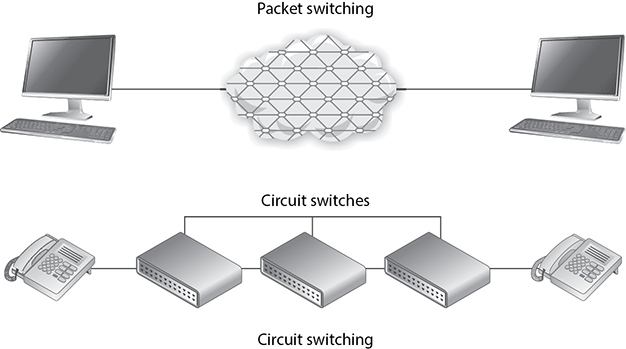
Figure 11-36 Circuit switching provides one road for a communication path, whereas packet switching provides many different possible roads.
When the source system makes a connection with the destination system, they set up a communication channel. If the two systems are local to each other, fewer devices need to be involved with setting up this channel. The farther the two systems are from each other, the more the devices are required to be involved with setting up the channel and connecting the two systems.
An example of how a circuit-switching system works is daily telephone use. When one person calls another, the same type of dedicated virtual communication link is set up. Once the connection is made, the devices supporting that communication channel do not dynamically move the call through different devices, which is what takes place in a packet-switching environment. The channel remains configured at the original devices until the call (connection) is done and torn down.
Packet switching, on the other hand, does not set up a dedicated virtual link, and packets from one connection can pass through a number of different individual devices (see the top of Figure 11-36), instead of all of them following one another through the same devices. Some examples of packet-switching technologies are the Internet, X.25, and frame relay. The infrastructure that supports these methods is made up of routers and switches of different types. They provide multiple paths to the same destinations, which offers a high degree of redundancy.
In a packet-switching network, the data is broken up into packets containing frame check sequence (FCS) numbers. These packets go through different devices, and their paths can be dynamically altered by a router or switch that determines a better route for a specific packet to take. Once the packets are received at the destination computer, all the packets are reassembled according to their FCS numbers and processed.
Because the path a packet will take in a packet-switching environment is not set in stone, there could be variable delays when compared to a circuit-switching technology. This is okay, because packet-switching networks usually carry data rather than voice. Because voice connections clearly detect these types of delays, in many situations a circuit-switching network is more appropriate for voice connections. Voice calls usually provide a steady stream of information, whereas a data connection is “burstier” in nature. When you talk on the phone, the conversation keeps a certain rhythm. You and your friend do not talk extremely fast and then take a few minutes in between conversations to stop talking and create a void with complete silence. However, this is usually how a data connection works. A lot of data is sent from one end to the other at one time, and then dead time occurs until it is time to send more data.
Frame Relay
For a long time, many organizations used dedicated links to communicate with other organizations. Company A had a pipeline to company B that provided a certain bandwidth 24 hours a day and was not used by any other entities. This was great because only the two companies could use the line, so a certain level of bandwidth was always available, but it was expensive, and most organizations did not use the full bandwidth each and every hour the link was available. Thus, organizations spent a lot of money for a service they did not use all the time. Later, to avoid this unnecessary cost, organizations turned to using frame relay instead of dedicated lines.
EXAM TIP
Frame relay is an obsolescent technology. It is still in limited use, however, and you should be familiar with it for the CISSP exam.
Frame relay is a WAN technology that operates at the data link layer. It is a WAN solution that uses packet-switching technology to let multiple organizations and networks share the same WAN medium, devices, and bandwidth. Whereas direct point-to-point links have a cost based on the distance between the endpoints, the frame relay cost is based on the amount of bandwidth used. Because several organizations and networks use the same medium and devices (routers and switches), the cost can be greatly reduced per organization compared to dedicated links.
If a company knows it will usually require a certain amount of bandwidth each day, it can pay a certain fee to make sure this amount of bandwidth is always available to it. If another company knows it will not have a high bandwidth requirement, it can pay a lower fee that does not guarantee the higher bandwidth allocation. This second company will have the higher bandwidth available to it anyway—at least until that link gets busy, and then the bandwidth level will decrease. (Organizations that pay more to ensure that a higher level of bandwidth will always be available pay a committed information rate, or CIR.)
Two main types of equipment are used in frame relay connections: DTE and DCE, both of which were previously introduced in the discussion of CSU/DSU. The DTE is usually a customer-owned device, such as a router or switch, that provides connectivity between the organization’s own network and the frame relay network. DCE is the service provider’s device, or telecommunications company’s device, that does the actual data transmission and switching in the frame relay cloud. So the DTE is an organization’s ramp onto the frame relay network, and the DCE devices actually do the work within the frame relay cloud.
The frame relay cloud is the collection of DCE devices that provides switching and data communications functionality. Several service providers offer this type of service, and some providers use other providers’ equipment—it can all get confusing because a packet can take so many different routes. This collection is called a cloud to differentiate it from other types of networks and because when a packet hits this cloud, users do not usually know the route their frames will take. The frames will be sent either through permanent or switched virtual circuits that are defined within the DCE or through carrier switches.
NOTE
The term cloud is used in several technologies: Internet cloud, ATM cloud, frame relay cloud, cloud computing, and so on. The cloud is like a black box—we know our data goes in and we know it comes out, but we do not normally care about all the complex things that are taking place internally.
Frame relay is an any-to-any service that is shared by many users. As stated earlier, this is beneficial because the costs are much lower than those of dedicated leased lines. Because frame relay is shared, if one subscriber is not using its bandwidth, it is available for others to use. On the other hand, when traffic levels increase, the available bandwidth decreases. This is why subscribers who want to ensure a certain bandwidth is always available to them pay a higher CIR.
Figure 11-37 shows five sites being connected via dedicated lines versus five sites connected through the frame relay cloud. The first solution requires many dedicated lines that are expensive and not flexible. The second solution is cheaper and provides organizations much more flexibility.
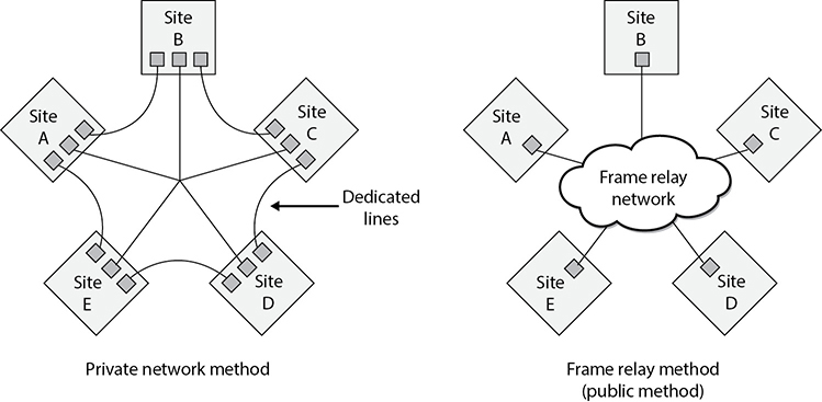
Figure 11-37 A private network connection requires several expensive dedicated links. Frame relay enables users to share a public network.
Virtual Circuits
Frame relay (and X.25) forwards frames across virtual circuits. These circuits can be either permanent, meaning they are programmed in advance, or switched, meaning the circuit is quickly built when it is needed and torn down when it is no longer needed. The permanent virtual circuit (PVC) works like a private line for a customer with an agreed-upon bandwidth availability. When a customer decides to pay for the CIR, a PVC is programmed for that customer to ensure it will always receive a certain amount of bandwidth.
Unlike PVCs, switched virtual circuits (SVCs) require steps similar to a dial-up and connection procedure. The difference is that a permanent path is set up for PVC frames, whereas when SVCs are used, a circuit must be built. It is similar to setting up a phone call over the public network. During the setup procedure, the required bandwidth is requested, the destination computer is contacted and must accept the call, a path is determined, and forwarding information is programmed into each switch along the SVC’s path. SVCs are used for teleconferencing, establishing temporary connections to remote sites, data replication, and voice calls. Once the connection is no longer needed, the circuit is torn down and the switches forget it ever existed.
Although a PVC provides a guaranteed level of bandwidth, it does not have the flexibility of an SVC. If a customer wants to use her PVC for a temporary connection, as mentioned earlier, she must call the carrier and have it set up, which can take hours.
X.25
X.25 is an older WAN protocol that defines how devices and networks establish and maintain connections. Like frame relay, X.25 is a switching technology that uses carrier switches to provide connectivity for many different networks. It also provides an any-to-any connection, meaning many users use the same service simultaneously. Subscribers are charged based on the amount of bandwidth they use, unlike dedicated links, for which a flat fee is charged.
Data is divided into 128 bytes and encapsulated in High-level Data Link Control (HDLC) frames. The frames are then addressed and forwarded across the carrier switches. Much of this sounds the same as frame relay—and it is—but frame relay is much more advanced and efficient when compared to X.25, because the X.25 protocol was developed and released in the 1970s. During this time, many of the devices connected to networks were dumb terminals and mainframes, the networks did not have built-in functionality and fault tolerance, and the Internet overall was not as foundationally stable and resistant to errors as it is today. When these characteristics were not part of the Internet, X.25 was required to compensate for these deficiencies and to provide many layers of error checking, error correcting, and fault tolerance. This made the protocol fat, which was required back then, but today it slows down data transmission and provides a lower performance rate than frame relay or ATM.
ATM
Asynchronous Transfer Mode (ATM) is another switching technology, but instead of being a packet-switching method, it uses a cell-switching method. ATM is a high-speed networking technology used for LAN, MAN, WAN, and service provider connections. Like frame relay, it is a connection-oriented switching technology, and creates and uses a fixed channel. IP is an example of a connectionless technology. Within the TCP/IP protocol suite, IP is connectionless and TCP is connection oriented. This means IP segments can be quickly and easily routed and switched without each router or switch in between having to worry about whether the data actually made it to its destination—that is TCP’s job. TCP works at the source and destination ends to ensure data was properly transmitted, and it resends data that ran into some type of problem and did not get delivered properly. When using ATM or frame relay, the devices in between the source and destination have to ensure that data gets to where it needs to go, unlike when a purely connectionless protocol is being used.
Since ATM is a cell-switching technology rather than a packet-switching technology, data is segmented into fixed-size cells of 53 bytes instead of variable-size packets. This provides for more efficient and faster use of the communication paths. ATM sets up virtual circuits, which act like dedicated paths between the source and destination. These virtual circuits can guarantee bandwidth and QoS. For these reasons, ATM is a good carrier for voice and video transmission.
ATM technology is used by carriers and service providers, and is the core technology of the Internet, but ATM technology can also be used for an organization’s private use in backbones and connections to the service provider’s networks.
Traditionally, organizations used dedicated lines, usually T-carrier lines, to connect to the public networks. However, organizations have also moved to implementing an ATM switch on their network, which connects them to the carrier infrastructure. Because the fee is based on bandwidth used instead of a continual connection, it can be much cheaper. Some organizations have replaced their Fast Ethernet and FDDI backbones with ATM. When an organization uses ATM as a private backbone, the organization has ATM switches that take the Ethernet frames, or whatever data link technology is being used, and frame them into the 53-byte ATM cells.
Quality of Service Quality of Service (QoS) is a capability that allows a protocol to distinguish between different classes of messages and assign priority levels. Some applications, such as video conferencing, are time sensitive, meaning delays would cause unacceptable performance of the application. A technology that provides QoS allows an administrator to assign a priority level to time-sensitive traffic. The protocol then ensures this type of traffic has a specific or minimum rate of delivery.
QoS allows a service provider to guarantee a level of service to its customers. QoS began with ATM and then was integrated into other technologies and protocols responsible for moving data from one place to another. Four different types of ATM QoS services (listed next) are available to customers. Each service maps to a specific type of data that will be transmitted.
• Constant bit rate (CBR) A connection-oriented channel that provides a consistent data throughput for time-sensitive applications, such as voice and video applications. Customers specify the necessary bandwidth requirement at connection setup.
• Variable bit rate (VBR) A connection-oriented channel best used for delay-insensitive applications because the data throughput flow is uneven. Customers specify their required peak and sustained rate of data throughput.
• Unspecified bit rate (UBR) A connectionless channel that does not promise a specific data throughput rate. Customers cannot, and do not need to, control their traffic rate.
• Available bit rate (ABR) A connection-oriented channel that allows the bit rate to be adjusted. Customers are given the bandwidth that remains after a guaranteed service rate has been met.
ATM was the first protocol to provide true QoS, but as the computing society has increased its desire to send time-sensitive data throughout many types of networks, developers have integrated QoS into other technologies.
QoS has three basic levels:
• Best-effort service No guarantee of throughput, delay, or delivery. Traffic that has priority classifications goes before traffic that has been assigned this classification. Most of the traffic that travels on the Internet has this classification.
• Differentiated service Compared to best-effort service, traffic that is assigned this classification has more bandwidth, shorter delays, and fewer dropped frames.
• Guaranteed service Ensures specific data throughput at a guaranteed speed. Time-sensitive traffic (voice and video) is assigned this classification.
Administrators can set the classification priorities (or use a policy manager product) for the different traffic types, which the protocols and devices then carry out.
Controlling network traffic to allow for the optimization or the guarantee of certain performance levels is referred to as traffic shaping. Using technologies that have QoS capabilities allows for traffic shaping, which can improve latency and increase bandwidth for specific traffic types, bandwidth throttling, and rate limiting.
HSSI
High-Speed Serial Interface (HSSI) is an interface used to connect multiplexers and routers to high-speed communications services such as ATM and frame relay. It supports speeds up to 52 Mbps, as in T3 WAN connections, which are usually integrated with router and multiplex devices to provide serial interfaces to the WAN. These interfaces define the electrical and physical interfaces to be used by DTE/DCE devices; thus, HSSI works at the physical layer.
WAN Technology Summary
We have covered several WAN technologies in the previous sections. Table 11-10 provides a snapshot of the important characteristics of each.
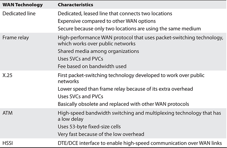
Table 11-10 Characteristics of WAN Technologies
Chapter Review
Before we can delve into communication and network security, we must first understand how networks are put together from the ground up. In this chapter, we started with a high-level overview of the OSI reference model because it will be the framework within which we will build the rest of our discussion of network security. You really need to become comfortable mapping technologies and protocols to the OSI reference model both for the CISSP exam and for your daily work.
We next took a look at the various technologies that allow us to build networks from the ground up. There are three types of LANs that you need to remember for the exam: Ethernet, Token Ring, and FDDI. Recall that LANs are limited in geographical scope but can be linked together using technologies like dedicated links, frame relay, SONET, and ATM to form MANs and WANs. Once you extend past the local area (and oftentimes even within it), you’ll need routers to break up broadcast domains and link together the pieces of your MAN or WAN.
Quick Review
• A protocol is a set of rules that dictates how computers communicate over networks.
• The application layer, layer 7, has services and protocols required by the user’s applications for networking functionality.
• The presentation layer, layer 6, formats data into a standardized format and deals with the syntax of the data, not the meaning.
• The session layer, layer 5, sets up, maintains, and breaks down the dialog (session) between two applications. It controls the dialog organization and synchronization.
• The transport layer, layer 4, provides end-to-end transmissions.
• The network layer, layer 3, provides routing, addressing, and fragmentation of packets. This layer can determine alternative routes to avoid network congestion. Routers work at the network layer, layer 3.
• The data link layer, layer 2, prepares data for the network medium by framing it. This is where the different LAN and WAN technologies work.
• The physical layer, layer 1, provides physical connections for transmission and performs the electrical encoding of data. This layer transforms bits to electrical signals.
• A network topology describes the arrangement of computers and devices.
• In a bus topology, a single cable runs the entire length of the network and nodes attach to it through drop points.
• In a star topology, all nodes connect to a central device such as a switch using a dedicated link.
• In a mesh topology, all nodes are connected to each other in a non-uniform manner that provides multiple paths to most or all the nodes on the network.
• A ring topology has a series of devices connected by unidirectional transmission links that form a closed loop and do not connect to a central system.
• Ethernet uses CSMA/CD, which means all computers compete for the shared network cable, listen to learn when they can transmit data, and are susceptible to data collisions.
• Token Ring, IEEE 802.5, is an older LAN implementation that uses a token-passing technology.
• FDDI is a LAN and MAN technology, usually used for backbones, that uses token-passing technology and has redundant rings in case the primary ring goes down.
• TCP/IP is a suite of protocols that is the de facto standard for transmitting data across the Internet. TCP is a reliable, connection-oriented protocol, while IP is an unreliable, connectionless protocol.
• Data is encapsulated as it travels down the network stack on the source computer, and the process is reversed on the destination computer. During encapsulation, each layer adds its own information so the corresponding layer on the destination computer knows how to process the data.
• Two main protocols at the transport layer are TCP and UDP.
• UDP is a connectionless protocol that does not send or receive acknowledgments when a datagram is received. It does not ensure data arrives at its destination. It provides “best-effort” delivery.
• TCP is a connection-oriented protocol that sends and receives acknowledgments. It ensures data arrives at the destination.
• ARP translates the IP address into a MAC address (physical Ethernet address), while RARP translates a MAC address into an IP address.
• ICMP works at the network layer and informs hosts, routers, and devices of network or computer problems. It is the major component of the ping utility.
• DNS resolves hostnames into IP addresses and has distributed databases all over the Internet to provide name resolution.
• Altering an ARP table so an IP address is mapped to a different MAC address is called ARP poisoning and can redirect traffic to an attacker’s computer or an unattended system.
• Routers link two or more network segments, where each segment can function as an independent network. A router works at the network layer, works with IP addresses, and has more network knowledge than bridges, switches, or repeaters.
• IPv4 uses 32 bits for its addresses, whereas IPv6 uses 128 bits; thus, IPv6 provides more possible addresses with which to work.
• NAT is used when organizations do not want systems to know internal hosts’ addresses, and it enables organizations to use private, nonroutable IP addresses.
• Subnetting allows large IP address ranges to be divided into smaller, logical, and easier-to-maintain network segments.
• Dedicated links are usually the most expensive type of WAN connectivity method because the fee is based on the distance between the two destinations rather than on the amount of bandwidth used. T1 and T3 are examples of dedicated links.
• Frame relay and X.25 are packet-switched WAN technologies that use virtual circuits instead of dedicated ones.
• ATM transfers data in fixed cells, is a WAN technology, and transmits data at very high rates. It supports voice, data, and video applications.
• Circuit-switching technologies set up a circuit that will be used during a data transmission session. Packet-switching technologies do not set up circuits—instead, packets can travel along many different routes to arrive at the same destination.
• Three main types of multiplexing are statistical time division, frequency division, and wave division.
Questions
Please remember that these questions are formatted and asked in a certain way for a reason. Keep in mind that the CISSP exam is asking questions at a conceptual level. Questions may not always have the perfect answer, and the candidate is advised against always looking for the perfect answer. Instead, the candidate should look for the best answer in the list.
1. Which of the following protocols is considered connection-oriented?
A. IP
B. ICMP
C. UDP
D. TCP
2. Which of the following shows the layer sequence as layers 2, 5, 7, 4, and 3?
A. Data link, session, application, transport, and network
B. Data link, transport, application, session, and network
C. Network, session, application, network, and transport
D. Network, transport, application, session, and presentation
3. Metro Ethernet is a MAN protocol that can work in network infrastructures made up of access, aggregation, metro, and core layers. Which of the following best describes these network infrastructure layers?
A. The access layer connects the customer’s equipment to a service provider’s aggregation network. Aggregation occurs on a core network. The metro layer is the metropolitan area network. The core connects different metro networks.
B. The access layer connects the customer’s equipment to a service provider’s core network. Aggregation occurs on a distribution network at the core. The metro layer is the metropolitan area network.
C. The access layer connects the customer’s equipment to a service provider’s aggregation network. Aggregation occurs on a distribution network. The metro layer is the metropolitan area network. The core connects different access layers.
D. The access layer connects the customer’s equipment to a service provider’s aggregation network. Aggregation occurs on a distribution network. The metro layer is the metropolitan area network. The core connects different metro networks.
4. Systems that are built on the OSI model are considered open systems. What does this mean?
A. They do not have authentication mechanisms configured by default.
B. They have interoperability issues.
C. They are built with internationally accepted protocols and standards so they can easily communicate with other systems.
D. They are built with international protocols and standards so they can choose what types of systems they will communicate with.
5. Which of the following protocols work in the following layers: application, data link, network, and transport?
A. FTP, ARP, TCP, and UDP
B. FTP, ICMP, IP, and UDP
C. TFTP, ARP, IP, and UDP
D. TFTP, RARP, IP, and ICMP
6. What takes place at the data link layer?
A. End-to-end connection
B. Dialog control
C. Framing
D. Data syntax
7. What takes place at the session layer?
A. Dialog control
B. Routing
C. Packet sequencing
D. Addressing
8. Which best describes the IP protocol?
A. A connectionless protocol that deals with dialog establishment, maintenance, and destruction
B. A connectionless protocol that deals with the addressing and routing of packets
C. A connection-oriented protocol that deals with the addressing and routing of packets
D. A connection-oriented protocol that deals with sequencing, error detection, and flow control
9. Which of the following is not one of the messages exchanged during the DHCP lease process?
i. Discover
ii. Offer
iii. Request
iv. Acknowledgment
A. All of them are exchanged
B. None of them are exchanged
C. i, ii
D. ii, iii
10. An effective method to shield networks from unauthenticated DHCP clients is through the use of __________ on network switches.
A. DHCP snooping
B. DHCP protection
C. DHCP shielding
D. DHCP caching
Answers
1. D. TCP is the only connection-oriented protocol listed. A connection-oriented protocol provides reliable connectivity and data transmission, while a connectionless protocol provides unreliable connections and does not promise or ensure data transmission.
2. A. The OSI model is made up of seven layers: application (layer 7), presentation (layer 6), session (layer 5), transport (layer 4), network (layer 3), data link (layer 2), and physical (layer 1).
3. D. The access layer connects the customer’s equipment to a service provider’s aggregation network. Aggregation occurs on a distribution network. The metro layer is the metropolitan area network. The core connects different metro networks.
4. C. An open system is a system that has been developed based on standardized protocols and interfaces. Following these standards allows the systems to interoperate more effectively with other systems that follow the same standards.
5. C. Different protocols have different functionalities. The OSI model is an attempt to describe conceptually where these different functionalities take place in a networking stack. The model attempts to draw boxes around reality to help people better understand the stack. Each layer has a specific functionality and has several different protocols that can live at that layer and carry out that specific functionality. These listed protocols work at these associated layers: TFTP (application), ARP (data link), IP (network), and UDP (transport).
6. C. The data link layer, in most cases, is the only layer that understands the environment in which the system is working, whether it be Ethernet, Token Ring, wireless, or a connection to a WAN link. This layer adds the necessary headers and trailers to the frame. Other systems on the same type of network using the same technology understand only the specific header and trailer format used in their data link technology.
7. A. The session layer is responsible for controlling how applications communicate, not how computers communicate. Not all applications use protocols that work at the session layer, so this layer is not always used in networking functions. A session layer protocol sets up the connection to the other application logically and controls the dialog going back and forth. Session layer protocols allow applications to keep track of the dialog.
8. B. The IP protocol is connectionless and works at the network layer. It adds source and destination addresses to a packet as it goes through its data encapsulation process. IP can also make routing decisions based on the destination address.
9. B. The four-step DHCP lease process is
1. DHCPDISCOVER message: This message is used to request an IP address lease from a DHCP server.
2. DHCPOFFER message: This message is a response to a DHCPDISCOVER message, and is sent by one or numerous DHCP servers.
3. DHCPREQUEST message: The client sends this message to the initial DHCP server that responded to its request.
4. DHCPACK message: This message is sent by the DHCP server to the DHCP client and is the process whereby the DHCP server assigns the IP address lease to the DHCP client.
10. A. DHCP snooping ensures that DHCP servers can assign IP addresses to only selected systems, identified by their MAC addresses. Also, advance network switches now have the capability to direct clients toward legitimate DHCP servers to get IP addresses and to restrict rogue systems from becoming DHCP servers on the network.