EXAM ALERT
Be sure to review basic virtual LAN (VLAN) and IEEE 802.1Q trunk configuration and operation from the prerequisite CCNA material.
VLAN hopping attacks occur when an attacker tricks a switch into allowing traffic to hop to a different VLAN than the VLAN assigned to the port to which they are connected. Normally, routers are required to route traffic between VLANs at layer 3.
NOTE
Recall “router-on-a-stick” and inter-VLAN routing from your CCNA studies. For traffic to move between VLANs, it needs to be routed either by a router integral to the switch, or by an external router attached to the switch by a trunk port. When diagramming the latter scenario, the router appears connected to the switch by a stick, hence the term “router-on-a-stick.” VLAN hopping attacks break this rule, and trick the switch to allow traffic that arrives on a switch port to hop to a different VLAN without involving a router.
Allowing traffic to hop to a different VLAN is very dangerous; if an attacker can fool the switch into revealing traffic from another VLAN, sensitive information carried in cleartext, such as passwords, may be obtained. For example, an attacker might be able to hop into the management VLAN, a mission-critical traffic plane whose use we first examined in Figure 4-1, our reference network diagram in Chapter 4, “Implementing Secure Management and Hardening the Router.”
This is ironic because, according to Cisco, the three main advantages of VLANS are as follows:
![]() Segmentation
Segmentation
![]() Flexibility
Flexibility
![]() Security
Security
The first and third points are related. By segmenting a network into different virtual broadcast domains, security is achieved; under normal operations, a user connected to a switch port is able to see only the following traffic and only in their VLAN:
![]() Unicast traffic:These are frames destined to the user’s PC.
Unicast traffic:These are frames destined to the user’s PC.
![]() Flooded traffic:These are frames that are forwarded out all but the originating interface and consist of the following:
Flooded traffic:These are frames that are forwarded out all but the originating interface and consist of the following:
![]() Unknown unicast frames
Unknown unicast frames
![]() Majority of multicast frames
Majority of multicast frames
![]() Broadcast frames
Broadcast frames
We examine two common VLAN hopping attacks, as follows:
![]() VLAN hopping by rogue trunk
VLAN hopping by rogue trunk
![]() VLAN hopping by double tagging
VLAN hopping by double tagging
VLAN hopping by rogue trunk is one of the simplest attacks to explain and also one of the simplest to mitigate. A rogue trunk (like a rogue access point) is where an attacker sets up an unauthorized trunk on the switch port to which they are connected. Trunks (either Cisco ISL or IEEE 802.1Q) carry traffic from all VLANs by default. Add to this the fact that Cisco switch ports will auto-negotiate trunking, and you have a problem. Here is how such an attack might be performed:
-
An attacker needs just to trick the switch into negotiating a trunk by using the signaling protocol for automatic trunk negotiation, Dynamic Trunking Protocol (DTP). The attacker connects a rogue switch to an unused switch port and spoofs DTP messages to automatically negotiate and thus turn on trunking between the rogue switch and the victim switch.
-
The attacker can now send traffic into the network tagged with the VLAN ID of a VLAN that has been learned from the trunk.
Attack mitigation is simple:
![]() Turn off trunking on ports unless they specifically need it:
Turn off trunking on ports unless they specifically need it:
Catalyst1(config-if)#switchport mode access
![]() Disable DTP on the remaining ports that require trunking and manually enable trunking on them:
Disable DTP on the remaining ports that require trunking and manually enable trunking on them:
Catalyst1(config-if)#switchport mode trunk
Catalyst1(config-if)#switchport nonegotiate
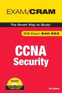
This is sometimes also called a double encapsulation attack. This type of attack leverages how the switch hardware works. Figure 10.1 illustrates the attack. When most switches receive a frame with 802.1Q encapsulation (indicated by its Ethertype), they unencapsulate them only once, assuming (correctly) that normally 802.1Q frames have only one frame tag in them.
The following is a detailed explanation of the numbered steps in Figure 10-1:
-
Knowing that the switch will only unencapsulate 802.1Q frames once, the attacker will send broadcast or unicast traffic into the switch, hiding a tagged 802.1Q frame inside another tagged 802.1Q frame. For example, VLAN 99 might be hidden inside VLAN 1. There is some guesswork involved in this attack; once the outer 802.1Q frame has been stripped of its tag, the inner frame will only travel in a trunk (to another switch) whose native VLAN is the same as the VLAN tag of the outer 802.1Q frame.
-
Because this native VLAN traffic is not tagged (per the 802.1Q protocol), the inner frame is transmitted in trunks to neighbor switches of the victim switch.
-
All the victim switch’s neighbors see is an 802.1Q frame tagged with VLAN 99, and they do what switches do: They examine the VLAN tag, and if the frame is a broadcast, it is flooded to all ports and trunks in that VLAN. If the frame is a unicast, and the entry is in the switch’s Content Addressable Memory (CAM) table, it is forwarded just to the port where the victim host is connected. (Figure 10-1 illustrates what happens when an unknown unicast is flooded.)
NOTE
Both types of VLAN hopping attacks are only possible when the switch’s ports are misconfigured.
A double-tagging VLAN hopping attack is unidirectional and works only if the attacker and the trunk port(s) are in the same native VLAN. The best way to prevent this type of attack is to make sure that the native VLAN of the trunked ports is different than any of the users’ ports (VLAN 10, for example):
Catalyst1(config-if)switchport trunk native vlan 10
EXAM ALERT
Stop! If you are unfamiliar with spanning tree protocol (STP) operation, now is the time for you to review the subject from the CCNA prerequisite material. Pay particular attention to the role of the root bridge in spanning tree, as well as the role that Bridge Protocol Data Units (BPDUs) play in electing the root bridge.
In an STP manipulation attack, an attacker connects to a switch port and either directly themselves, or through the use of a rogue switch, attempts to manipulate Spanning Tree Protocol (STP) parameters to become the root bridge. Because the root bridge is responsible for calculating the spanning tree from topology changes advertised by non-root bridges, attackers see a variety of frames that they would normally not see.
To perform this attack, the attacker needs only to inject BPDU frames with a Bridge ID (BID) that is lower than the current root bridge into the network. Recall that the BID is made up of a 16-bit Bridge Priority + 48-bit MAC address. If the attacker selects a bridge priority (range 0–65535) that is lower than the existing root bridge, they will become root. The default priority for a Cisco Catalyst switch is 32768. The attacker could simply guess this, or they could find out what the priority is for the STP root bridge by using a protocol analyzer on a switch port, recognizing that such multicast traffic is flooded by the switch.
NOTE
You might have heard about another spanning tree protocol called Per VLAN Spanning Tree Plus (PVST+). One of the features of PVST+ is its ability to elect a different root bridge per VLAN. Its use is very common in large switched networks with multiple VLANs.
With PVST+, the first 16 bits of the bridge ID have been remapped to include the VLAN ID and other information. Thus, not all 16 bits are used to define the bridge priority. The attacker could learn what type of bridge ID is being used by using a protocol analyzer on a switch port and examining the BPDUs. Then, they need to only inject frames with the more attractive bridge ID per the protocol used in an attempt to become the root bridge.
There are three features that can be used together or separately to mitigate STP manipulation attacks. (They are most effective when used together.) These features are as follows:
-
The Portfast feature, which disables spanning tree on a port.
-
The BPDU guard feature, which guards against learning erroneous STP information on a port.
-
The Root guard feature, which explicitly disables root bridge election on a port.
An important first step to mitigate this type of attack is to ensure that the attacker can only guess information about the network topology and can’t directly read it. For example, any port that is not participating in the STP calculation can be put in portfast mode. This prevents the switch from putting that interface in blocking mode.
EXAM ALERT
Be very sure that this switch port is not part of a topological loop before you put it in portfast mode. Portfast means that you think you are smarter than STP, which unfortunately (for many of us) is not the case!
This command enables portfast globally on all non-trunking ports:
Catalyst1(config)#spanning-tree portfast default
If you want to turn on portfast selectively on an interface, use this command:
Catalyst1(config-if)#spanning-tree portfast
As a second step toward mitigating an STP attack, consider setting up BPDU guard on an interface. With BPDU guard enabled, an interface can be put into a blocking state when it receives a BPDU. This seems a bit severe, like cutting your nose off to spite your face, but remember that any security policy is a balance between usability and security. With BPDU guard enabled, an attacker will be unable to force root bridge election because the BPDU will be refused on the port that they are connected to. It is also used to enforce the boundaries of the spanning tree, recognizing that typically it is only in parts of a network where loop-causing redundancies might be deployed.
To enable BPDU guard globally on all ports where portfast is enabled, use the following command:
Catalyst1(config)#spanning-tree portfast bpduguard default
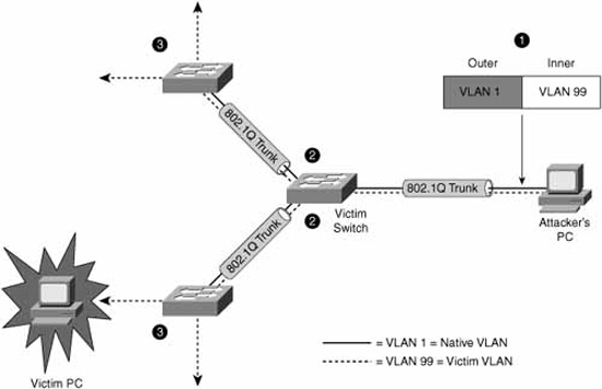
Intuitively, BPDU guard complements portfast and can only be enabled on ports where portfast has been enabled in any case. To verify BPDU guard, use the following command:
The preceding command output indicates that portfast and BPDU guard are enabled on that switch.
The third step is to enable the root guard feature. The root guard feature is enabled on a per-interface basis. If enabled, the switch will examine any received BPDU on that interface and compare it with the current root bridge. If the BID is superior to that of the current root bridge, the port is moved to a root-inconsistent state (effectively a listening state) and ceases to pass traffic. This effectively mitigates an STP attack. When the superior BPDUs cease, the port transitions back to a normal mode. Here is the command to enable root guard on an interface:
Catalyst1(config-if)#spanning-tree guard root
A switch’s Content Addressable Memory (CAM) table contains MAC addresses that can be reached, organized by the port where they have been learned, as well as the associated VLAN ID. The CAM table can hold a finite number of entries depending on switch model. For example, many 2900 series Catalyst switches are designed to contain as many as 4,096 entries, whereas higher-end switches such as the 6500 series Catalyst switches can contain many tens of thousands of entries. Switches learn these MAC addresses by analyzing the source address of Ethernet frames that arrive on a particular port.
A CAM table overflow attack leverages this simple process by injecting thousands of frames with bogus source MAC addresses on a single port. An example of such a utility is macof. When the CAM table reaches capacity with these bogus MAC addresses, older, legitimate MAC addresses are pushed out of the CAM table.
Subsequent frames whose destination address is the MAC address of a legitimate host are flooded out all of the switch’s ports as with any unknown unicast traffic. Attackers, listening on any port, will be able to capture a flood of traffic that they would not normally see. For example, frames encapsulating sensitive traffic that are destined to a network server might be visible by the attacker.
This type of attack can be mitigated by configuring port security. Port security is explained in the “Configuring Port Security” section to follow.
In a MAC address spoofing attack, an attacker injects frames into a switch port with the source address of a known host. Assuming that the spoofed host is not transmitting, this causes the switch to send frames that would normally be destined to the spoofed host’s switch port to the attacker’s switch port instead. Again, the attacker is leveraging the switch’s learning process.
This attack also can be mitigated with port security. Port security is explained in the following “Configuring Port Security” section.
Essentially, port security enables you to configure a switch port to allow specific statically-assigned MAC addresses or to set a maximum for the number of MAC addresses learned on that port. For example, setting a finite number of MAC addresses that can be learned on a port would effectively mitigate a MAC address spoofing attack. As another example, a CAM table overflow attack could be mitigated by using port security to define specific MAC addresses that can be reached by a specific port, thus limiting the scope of flooding of unknown unicast traffic. Furthermore, port security can be tuned as to what action will be performed when that maximum has been reached or when a MAC address doesn’t match the statically assigned MAC address(es).
The switch could be configured to
![]() Send an alert to the console or a logging server.
Send an alert to the console or a logging server.
![]() Simply not accept the violating frame.
Simply not accept the violating frame.
![]() Shut down the port altogether.
Shut down the port altogether.
![]() Perform a combination of these actions.
Perform a combination of these actions.
NOTE
Cisco recommends that a port be shut down when a violation occurs because it will probably be eventually disabled anyway if an attack creates too much load.
Also, port security cannot be configured on trunk ports because it is only appropriate on access ports.
Because port security is only applicable to access ports (and not trunks), you need to enable a port for access mode. Use this interface command:
Catalyst1(config-if)#switchport mode access
To enable port security on a port, use this command:
Catalyst1(config-if)#switchport port-security
By default, when you enable port security on a Catalyst switch port, it will learn a maximum of 132 secure MAC addresses; the violation mode (that is, the action it will take if there is a violation) is to send an alert. The following optional settings tune the configuration.
EXAM ALERT
If you are asked in the exam what the port security defaults are for a Catalyst switch port, the right answer is that a maximum of 132 secure MAC addresses are learned on a switch port. In reality, the default for the maximum number of secure MAC addresses is dependent on the model of the switch. For example, a Catalyst 2960 defaults to a maximum of one secure MAC address when port security is enabled on a port.
To set a maximum number of MAC addresses that can be learned on a port, use the switchport port-security maximum command. For example, the following command allows a maximum of 32 addresses to be learned on a port:
Catalyst1(config-if)#switchport port-security maximum 32
To set the violation mode for the port, use this command:
switchport port-security violation {protect | restrict | shutdown |
shutdown vlan}
The following is a detailed explanation of the command’s syntax:
![]() protect:When the maximum number of secure MAC addresses configured on a port is reached, subsequent frames are silently dropped (that is, no notification) until the number of MAC addresses learned falls back below the maximum.
protect:When the maximum number of secure MAC addresses configured on a port is reached, subsequent frames are silently dropped (that is, no notification) until the number of MAC addresses learned falls back below the maximum.
![]() restrict:Same as protect, except a notification of the violation is sent. If you have Simple Network Management Protocol (SNMP) set up, a trap is sent to the SNMP Network Management Station (NMS). If syslog is set up, a syslog message is logged. The violation counter is also incremented.
restrict:Same as protect, except a notification of the violation is sent. If you have Simple Network Management Protocol (SNMP) set up, a trap is sent to the SNMP Network Management Station (NMS). If syslog is set up, a syslog message is logged. The violation counter is also incremented.
![]() shutdown:This setting will shut down the port on which the violation occurred. The port is put in an error-disabled state and the port LED is extinguished. It also sends an SNMP trap and/or syslog message per the restrict option.
shutdown:This setting will shut down the port on which the violation occurred. The port is put in an error-disabled state and the port LED is extinguished. It also sends an SNMP trap and/or syslog message per the restrict option.
![]() shutdown vlan:Same as shutdown, but the switch port will only be put in an error-disabled state for the VLAN in which the violation occurred.
shutdown vlan:Same as shutdown, but the switch port will only be put in an error-disabled state for the VLAN in which the violation occurred.
In this example, the switch’s port will be error-disabled for frames for VLAN 5 if there has been a violation in that VLAN:
Catalyst1(config-if)#switchport port-security violation shutdown vlan 5
Port security can be configured to allow only specified MAC addresses to use a port. The switchport port-security mac-address command needs to be entered for every secure MAC address; for example:
Catalyst1(config-if)#switchport port-security mac-address 0013.b638.8567
Sticky learning means that designated MAC addresses learned on a switch port can be configured to age out more slowly than other dynamically learned entries. They are harder to get rid of; thus, they are sticky. To enable sticky learning of secure MAC addresses on a port, you can use this command:
Catalyst1(config-if)#switchport port-security mac-address sticky
In this manner, the secure MAC addresses are designated as sticky; thus, they remain in the running configuration on the switch.
You also can define how long the secure addresses that are learned on a switch port stay in the CAM table. The command to configure this is the switchport port-security aging command:
switchport port-security aging {static | time time | type {absolute |
inactivity}}
The command options are as follows:
![]() static:Enables aging for static secure MAC addresses on this port.
static:Enables aging for static secure MAC addresses on this port.
![]() time:Specifies the aging time for this port (0 to 1,440 minutes). If set to 0, aging is disabled.
time:Specifies the aging time for this port (0 to 1,440 minutes). If set to 0, aging is disabled.
![]() type absolute:Sets the aging type to absolute. After the time specified expires, all secure MAC addresses are removed from the secure address list.
type absolute:Sets the aging type to absolute. After the time specified expires, all secure MAC addresses are removed from the secure address list.
![]() type inactivity:Sets the aging type to inactivity. After the time specified expires, all secure MAC addresses are removed from the secure address list.
type inactivity:Sets the aging type to inactivity. After the time specified expires, all secure MAC addresses are removed from the secure address list.
For example, if you wanted secure MAC addresses to age out of the CAM table after 100 minutes of inactivity, you could type this command:
Catalyst1(config-if)#switchport port-security aging time 100
Catalyst1(config-if)#switchport port-security aging type inactivity
To verify port security, you can use the show port-security command or the show port-security interface interface-id command. Here are some examples of the output of these commands:
Catalyst1#show port-security
Secure Port MaxSecureAddr CurrentAddr SecurityViolation Security Action
(Count) (Count) (Count)
Gig0/1 32 29 0 Shutdown
---------------------------------------------------------------------------
Total Addresses in System (excluding one mac per port) : 0
Max Addresses limit in System (excluding one mac per port) : 6272
Catalyst1#show port-security interface gigabitEthernet 0/1
Port Security : Enabled
Port Status : Secure-down
Violation Mode : Shutdown
Aging Time : 100 mins
Aging Type : Inactivity
SecureStatic Address Aging : Disabled
Maximum MAC Addresses : 32
Total MAC Addresses : 29
Configured MAC Addresses : 0
Sticky MAC Addresses : 0
Last Source Address:Vlan : 0000.0000.0000:0
Security Violation Count : 0
In the output of the show port-security command, port security is enabled on port Gig0/1 with a maximum MAC address count of 32. There have been 29 MAC addresses learned on the port, and there have been no violations. The aging time (we set this previously) is set to 100 minutes, and the aging type is inactivity.
The output of the show port-security interface gigabitEthernet 0/1 command indicates that a policy violation has occurred because the port has been placed in a secure-down status.
EXAM ALERT
A port that is in an err-disabled state is one that has been disabled due to a port security violation. There are two ways to bring a port out of the err-disabled state, as follows:
-
Enter the errdisable recovery cause psecure-violation command in global configuration.
-
Alternatively, you can manually re-enable the specific port by toggling it with the shutdown and no shutdown interface configuration commands.
To view all the secure MAC addresses on all interfaces, you can use the show port-security address command. If you want to see the secure MAC addresses learned on one specific interface, you can use the show port-security interface interface-id address form of the command. Both forms of the command also show you the aging information for each address. Here’s an example:

In the example, port GigE0/1 is in VLAN 10 and has a secured MAC address of 0000.e3fd.39ca. The device with that MAC address can use port GigE0/1, and there is a remaining age of 99 minutes for that entry.
Following is a high-level discussion of some additional switch security features that can be used by themselves or in conjunction with the mitigation techniques previously examined
In some situations, you might want to configure the switch to send a notification to an SNMP NMS when MAC addresses are learned by the system or deleted from the CAM table. An example of where this might be used could be a switch that is deployed in a particularly restrictive security zone in the network, like an R&D lab or a DMZ, and where you want to determine if there is anomalous MAC address learning behavior in that part of the network. The following command enables this feature:
Catalyst1(config)#mac-address-table notification
Only dynamic and secure MAC addresses generate a MAC address notification. Traps are not sent for self, multicast, or other static addresses.
NOTE
Use the mac-address-table notification command with caution. It can generate a lot of traffic to the NMS. You might consider changing the interval at which alerts are sent to the NMS by using the following format of the command:
Catalyst1(config)#mac-address-table notification interval 120
In this example, the interval at which events are trapped to the NMS server has been set to 120 seconds.
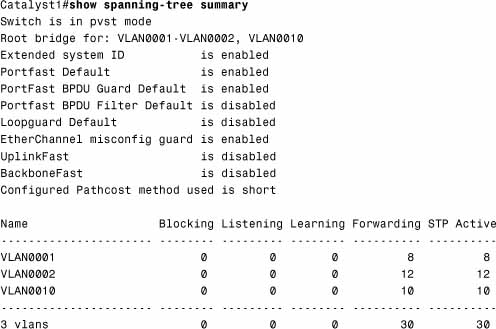
Chapter 8, “Network Security Using Cisco IOS IPS,” discusses how an IDS should be deployed in the network in such a way that it will see all the traffic in a particular part of the network. If it doesn’t see all the traffic, its effectiveness as an IDS is questionable at best. Referring to Figure 10-2, if an organization’s perimeter router is connected to an ISP router via a switch, an IDS deployed on a single switch port would normally see only flooded traffic, namely unknown unicasts, broadcasts, and multicasts. It would not see the majority of ingress and egress traffic in and out of the organization’s network, rendering it ineffective.
A way must be found to replicate the traffic that hits the GigE 0/1 interface to the GigE 0/2 interface where the IDS resides. This is the idea behind SPAN. The destination port (GigE 0/2, in our example) is dedicated to monitor the activity on another port or VLAN. SPAN can copy traffic sent or received. The port dedicated for SPAN use does not receive or forward any other traffic than that which is required for SPAN use. This type of port monitoring is often called port mirroring. SPAN does not affect switch operation.
The following are the commands to create a monitoring session, number 1, which mirrors traffic from gigabitEthernet 0/1 to gigabitEthernet 0/2. The encapsulation replicate part of the second command preserves the encapsulation method of the monitored port. For example, if the mirrored port is an IEEE 802.1Q trunk, the port that the frames are replicated to will see copies of tagged VLAN traffic and native VLAN traffic.
Catalyst1(config)# monitor session 1 source interface gigabitEthernet0/1
Catalyst1(config)# monitor session 1 destination interface
gigabitEthernet0/2 encapsulation replicate
Broadcast storms are not just a product of topological loops. If they were, then spanning tree would be the sole requirement for mitigating broadcast storms. Broadcast storms can also result from the following:
![]() DoS attacks
DoS attacks
![]() Poorly-designed, chatty applications
Poorly-designed, chatty applications
![]() Protocols that rely heavily on broadcasts (for example, NetBIOS, AppleTalk, and Novell)
Protocols that rely heavily on broadcasts (for example, NetBIOS, AppleTalk, and Novell)
Storm control is essentially a method of traffic suppression. A threshold is set for the number of incoming broadcast, multicast, and unicast frames that are allowed on each port. Frames are counted in a one-second interval, and the switch blocks broadcasts that rise above that threshold within that interval. Control frames such as BPDUs are exempt, but other, necessary traffic, such as frames that carry routing protocol packets, may be discarded. It is good practice to understand the type and disposition of protocol traffic that may arrive on a specific switch interface before setting these thresholds; weighing the likelihood of attack on that port against the criticality of traffic that needs to flow for normal operation.
In the end, storm control only treats the symptoms and not the cause of broadcasts if the problem is simply poor design. A network should be designed to limit the amount of broadcast and multicast traffic.
To enable storm control, use the following interface configuration command:
Catalyst1(config-if)#storm-control
You can then specify a traffic suppression level for the type of traffic in a variety of different ways:
![]() Percentage (up to two decimal places of accuracy) of total bandwidth on the port
Percentage (up to two decimal places of accuracy) of total bandwidth on the port
![]() Rate in packets per second (pps)
Rate in packets per second (pps)
![]() Rate in bits per second
Rate in bits per second
To verify the storm control that has been configured on a particular interface, you might choose to use the following command:
Catalyst1(config-if)#do show running-config interface GigabitEthernet0/1
Building configuration...
Current configuration : 271 bytes
!
interface GigabitEthernet0/1
storm-control broadcast level 62.50
storm-control multicast level pps 3k 2k
storm-control unicast level bps 50m 25m
storm-control action shutdown
end
In the previous CLI example
![]() Broadcast traffic is limited to no more than 62.5% of total bandwidth on the port, and traffic exceeding this threshold is blocked until it falls back to 62.5% (see the following note).
Broadcast traffic is limited to no more than 62.5% of total bandwidth on the port, and traffic exceeding this threshold is blocked until it falls back to 62.5% (see the following note).
![]() Multicast traffic is limited to no more than 3,000 packets per second on a rising threshold and continues to be blocked until the number of multicast packets per second drops to the falling threshold of 2,000.
Multicast traffic is limited to no more than 3,000 packets per second on a rising threshold and continues to be blocked until the number of multicast packets per second drops to the falling threshold of 2,000.
![]() Unicast traffic is limited to no more than 50 Mbps on a rising threshold and continues to be blocked until the falling threshold of 25 Mbps is reached.
Unicast traffic is limited to no more than 50 Mbps on a rising threshold and continues to be blocked until the falling threshold of 25 Mbps is reached.
![]() The port is shut down if any of these thresholds is exceeded.
The port is shut down if any of these thresholds is exceeded.
NOTE
If you define the threshold in pps or bps (as in this example of the storm-control command), you can use k, m, or g to specify thousand, millions, and billions of packets per second or bits per second respectively.
If a falling threshold is not specified (2k pps for multicasts and 25m bps for unicasts in this example), the traffic will be blocked until the traffic falls below the rising threshold.
For the action in the storm-control command, you can also specify the option trap, which sends an SNMP alert to the NMS when a storm occurs.
Cisco makes the following recommendations for switch security best practices:
![]() Secure management:Think security for switch management. Use SSH, a dedicated management VLAN, OOB, and so on as much as possible.
Secure management:Think security for switch management. Use SSH, a dedicated management VLAN, OOB, and so on as much as possible.
![]() Native VLAN:Always use a dedicated VLAN ID for trunk ports and avoid using VLAN 1 at all.
Native VLAN:Always use a dedicated VLAN ID for trunk ports and avoid using VLAN 1 at all.
![]() User ports:Non-trunking. (Cisco VoIP phones being the exception. See Chapter 9, “Introduction to Endpoint, SAN, and Voice Security.”)
User ports:Non-trunking. (Cisco VoIP phones being the exception. See Chapter 9, “Introduction to Endpoint, SAN, and Voice Security.”)
![]() Port security:Use for access ports whenever possible.
Port security:Use for access ports whenever possible.
![]() SNMP:Limit to the management VLAN if possible and treat community strings like superuser passwords. (See Chapter 4, “Implementing Secure Management and Hardening the Router,” for more information.)
SNMP:Limit to the management VLAN if possible and treat community strings like superuser passwords. (See Chapter 4, “Implementing Secure Management and Hardening the Router,” for more information.)
![]() STP attacks:Use BPDU guard and root guard.
STP attacks:Use BPDU guard and root guard.
![]() CDP:Only use if necessary. CDP should be left on for switch ports connected to VoIP phones. An attacker can learn much from CDP advertisements.
CDP:Only use if necessary. CDP should be left on for switch ports connected to VoIP phones. An attacker can learn much from CDP advertisements.
![]() Unused ports:Disable and put them in an unused VLAN for extra security.
Unused ports:Disable and put them in an unused VLAN for extra security.