
Virtual Private Networks (VPNs) are “virtual” in that they can either replace or, at least, complement existing network circuits, whether dial-in or between sites. VPNs are virtual in that sense, but hopefully there is nothing virtual about their privacy! According to Cisco, a good working definition of a VPN is as follows:
“A VPN [is] an encrypted connection between private networks over a public network, usually the Internet.”
Note
This is the definition that we use in this Exam Cram; although there are a number of other technologies that are called VPNs, they don’t provide for encryption and are thus hardly private. Historically, anything that created an IP tunnel was called a VPN. With such a loose definition, technologies that don’t provide encryption, such as Generic Routing Encapsulation (GRE) and IPsec tunnels using Authentication Header (AH), are still considered VPNs.
Any kind of network connection over a hostile network could benefit from implementing a VPN. Even on the inside of an organization’s perimeter, there are often places where a VPN is required to create a secure channel between network devices, as well as between people and network devices.
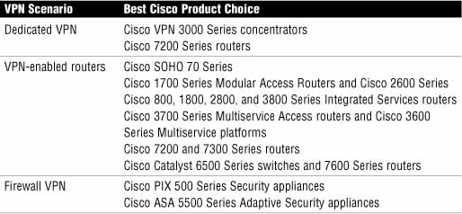
Table 7.1 lists the primary products in the Cisco product portfolio that can be used to deploy VPNs.
VPNs have many benefits, including the following:
![]() Cost Savings. The use of cost-effective, high-speed Internet technologies versus dedicated WAN links makes VPNs attractive.
Cost Savings. The use of cost-effective, high-speed Internet technologies versus dedicated WAN links makes VPNs attractive.
![]() Security. Advanced encryption, integrity, and authentication protocols provide for the highest protection against unauthorized access and data loss.
Security. Advanced encryption, integrity, and authentication protocols provide for the highest protection against unauthorized access and data loss.
![]() Scalability. VPNs can grow seamlessly without the need to add extra infrastructure, particularly when using the Internet.
Scalability. VPNs can grow seamlessly without the need to add extra infrastructure, particularly when using the Internet.
![]() Compatibility with Broadband Technology. VPN technology is largely independent of the underlying infrastructure, meaning that organizations can leverage on the most convenient broadband technology for the greatest flexibility.
Compatibility with Broadband Technology. VPN technology is largely independent of the underlying infrastructure, meaning that organizations can leverage on the most convenient broadband technology for the greatest flexibility.
There are two main types of VPNs:
![]() Site-to-site
Site-to-site
![]() Remote-access
Remote-access
With a site-to-site VPN, host devices operate behind network devices, such as IOS routers, which act as VPN gateways. This is an evolution of WAN technology. The host devices do not need any special software because the fact that there is a VPN between sites is immaterial to them, as the VPN is established between other devices, possibly their own default gateway in the simplest case.
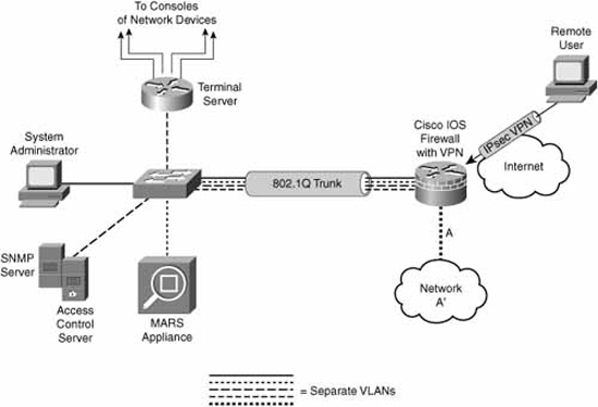
For example, if we configure IOS routers to be VPN gateways, the IP hosts in the production network behind the router would only have to attempt to establish a connection with a device on the inside of a peer network’s router. The host’s own VPN router would recognize that this site-to-site traffic from the local site to the remote site needs to be protected by the VPN and it would launch a tunnel (that is, the VPN) to its peer if one doesn’t already exist. This is illustrated with a small modification to the reference network layout that was first introduced in Figure 5.1 of Chapter 5, “Using Cisco IOS Firewalls to Implement a Network Security Policy.”
In Figure 7.1, all traffic between the A and B networks is protected inside a site-to-site VPN between router A and router B.

A device inside network A’—the system administrator PC, for example—would already have router A as its default gateway. Something magic happens from that PC’s perspective because when it tries to communicate with the private (RFC 1918) addresses in network B’, it gets a response. Breaking it down just a little bit, this is what happens:
![]() Confidentiality. The IP packet from the system administrator’s PC, from network A’ to network B’, is encrypted before it is encapsulated in another IP packet to router B. Similarly, upon receipt, router B decrypts the A’ to B’ packet before delivering it to the destination host on the B network.
Confidentiality. The IP packet from the system administrator’s PC, from network A’ to network B’, is encrypted before it is encapsulated in another IP packet to router B. Similarly, upon receipt, router B decrypts the A’ to B’ packet before delivering it to the destination host on the B network.
![]() Integrity. As we see in the section, “Conceptualizing a Site-to-Site IPsec VPN,” it’s possible that when the encrypted packet is sent to router B from router A, there is some integrity information added to the packet to add some assurance that the packet has not been tampered with in transit.
Integrity. As we see in the section, “Conceptualizing a Site-to-Site IPsec VPN,” it’s possible that when the encrypted packet is sent to router B from router A, there is some integrity information added to the packet to add some assurance that the packet has not been tampered with in transit.
![]() Authentication. Additionally, some authentication information might have been added to the encrypted IP packet to add assurance that it actually came from router A. Remember the C-I-A triad from Chapter 1, “Network Insecurity”? The “A” in the VPN C-I-A triad stands for authentication.
Authentication. Additionally, some authentication information might have been added to the encrypted IP packet to add assurance that it actually came from router A. Remember the C-I-A triad from Chapter 1, “Network Insecurity”? The “A” in the VPN C-I-A triad stands for authentication.
The optional integrity and authentication information will add some extra overhead per unit of data transmitted. It is up to the guidelines contained in the organization’s comprehensive security policy as to whether an acceptable tradeoff has been achieved between security and performance. Many VPN implementations implement confidentiality only, relying on other layers of the OSI model to provide for integrity and authentication outside the context of the VPN.
Note
Router B (or router A, for that matter) in Figure 7.1 could be any appropriate Cisco VPN product from Table 7.1.
In the same way that site-to-site VPNs evolved from traditional WANs, remote-access VPNs are an evolution of dial-up networking technology. Certainly the same principles of C-I-A apply here. The two most evident differences between remote-access and site-to-site VPNs are the following:
![]() Remote-access VPN clients initiate the VPN on demand.
Remote-access VPN clients initiate the VPN on demand.
![]() The remote-access client (whether a PC or a Cisco hardware device) requires Cisco VPN client software to connect.
The remote-access client (whether a PC or a Cisco hardware device) requires Cisco VPN client software to connect.
When implemented as a software solution on a remote user’s PC, this can be a very flexible solution. The teleworker can benefit from the same confidentiality, integrity, and authentication services of a site-to-site VPN, while using whatever Internet technologies are at their immediate disposal.
Referring to Figure 7.2, a corporate knowledge worker could be sipping designer coffee at their local coffee shop’s wireless hotspot while protecting corporate secrets on network A’ from hackers and the merely curious.
Cisco specifies another type of VPN that uses a web browser’s built-in Secure Sockets Layer (SSL) encryption to encrypt at the transport layer of the OSI model. One advantage of this solution is that in its simplest form, it doesn’t require the installation of additional software on a client PC. SSL VPN offers two modes of operation:
![]() Clientless. Uses a web portal to access hosts behind the gateway. Access to file and print shares, email servers, web servers, and other services is provided by the web portal’s interface.
Clientless. Uses a web portal to access hosts behind the gateway. Access to file and print shares, email servers, web servers, and other services is provided by the web portal’s interface.
![]() Client. Uses a thin client that provides an IP address and thus the ability to access applications with their native interface.
Client. Uses a thin client that provides an IP address and thus the ability to access applications with their native interface.
The SSL VPN solution is an emerging technology that complements Cisco’s IPsec VPN offerings.
Some disadvantages of the SSL VPN solution are as follows:
![]() Software-Only. One disadvantage is that it is a software-only solution in IOS routers; thus, it doesn’t take advantage of the hardware-accelerated onboard encryption in many router models. The router (and the client) CPU processes all the encryption.
Software-Only. One disadvantage is that it is a software-only solution in IOS routers; thus, it doesn’t take advantage of the hardware-accelerated onboard encryption in many router models. The router (and the client) CPU processes all the encryption.
![]() Cryptographic Security. Does not currently support the same level of encryption security as IPsec.
Cryptographic Security. Does not currently support the same level of encryption security as IPsec.
SSL VPNs have compatibility advantages. SSL VPNs can be configured and operate alongside other features on Cisco network devices. SSL VPNs are compatible with the following:
![]() Dynamic Multipoint VPNs (DMVPNs)
Dynamic Multipoint VPNs (DMVPNs)
![]() Cisco IOS Firewalls
Cisco IOS Firewalls
![]() IPsec
IPsec
![]() Intrusion Protection Systems (IPSs)
Intrusion Protection Systems (IPSs)
![]() Cisco Easy VPN (Cisco’s remote-access IPsec VPN solution)
Cisco Easy VPN (Cisco’s remote-access IPsec VPN solution)
![]() Network Address Translation (NAT)
Network Address Translation (NAT)
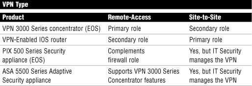
Cisco has a number of devices in its product portfolio that provide VPN services. Some of these devices are end-of-sale (EOS) and are marked as such in Table 7.2. EOS does not mean end-of-life! For example, there are literally hundreds of thousands of PIX firewalls in the field, and Cisco continues to support these devices with new OS updates and technical support.
Exam Alert
You should memorize Table 7.2, as Cisco just loves asking questions that refer to information found in tables.
Note
The VPN 3000 Series Concentrator was end-of-sale (EOS) in February 2007. The PIX 500 Series Security Appliances were recently announced EOS, with the last order date being July 28, 2008. They are not end-of-life (EOL) until July 27, 2013. Our focus will be on VPN-enabled IOS routers and the ASA 5500 Security Appliances. It’s also worth noting that Cisco recently announced (Q1 2008) two new ASA 5500 Series models: the ASA 5580-20 and 5580-40. These devices are positioned at the service provider level and have option cards that augment the ASA’s built-in hardware encryption by providing VPN hardware acceleration of 10,000 IPsec and 10,000 SSL connections simultaneously. Here is a link to a product matrix for the complete ASA 5500 Series portfolio: http://www.cisco.com/en/US/products/ps6120/prod_models_comparison.html.
Here is a link to Cisco’s Q&A about the EOS PIX firewalls:
Here are some of the VPN features of the Cisco VPN-enabled IOS routers:
![]() Voice and Video Enabled VPN (V3PN). Integration of QoS, IPsec, and VoIP (IP telephony).
Voice and Video Enabled VPN (V3PN). Integration of QoS, IPsec, and VoIP (IP telephony).
![]() IPsec Stateful Failover. Provides for network resiliency in site-to-site VPN configurations, in both stateless and stateful failover solutions. Options include the following:
IPsec Stateful Failover. Provides for network resiliency in site-to-site VPN configurations, in both stateless and stateful failover solutions. Options include the following:
![]() Dead Peer Detection (DPD)
Dead Peer Detection (DPD)
![]() Hot Standby Router Protocol (HSRP)
Hot Standby Router Protocol (HSRP)
![]() Reverse Route Injection (RRI)
Reverse Route Injection (RRI)
![]() Stateful Switchover (SSO)
Stateful Switchover (SSO)
![]() DMVPN. Enables automatic provisioning of site-to-site IPsec VPNs, putting together three Cisco IOS features:
DMVPN. Enables automatic provisioning of site-to-site IPsec VPNs, putting together three Cisco IOS features:
![]() Next Hop Resolution Protocol (NHRP)
Next Hop Resolution Protocol (NHRP)
![]() Multipoint GRE
Multipoint GRE
![]() IPsec VPN
IPsec VPN
![]() Cisco Easy VPN. Cisco’s common framework for remote-access IPsec VPNs.
Cisco Easy VPN. Cisco’s common framework for remote-access IPsec VPNs.
As you can infer from Table 7.2, the primary purpose of the ASA 5500 Series security appliances is as a perimeter security device that implements the organization’s comprehensive security policy. Because the IT security staff own the policy, they also own the security appliance and any policies, including the VPN, which are configured on it. In the context of VPN technology, the ASA 5500 Series of security appliances is Cisco’s direct replacement for the 3000 Series VPN concentrators, of which many tens of thousands still exist in the field. Here are some of the features of the ASA 5500 Series of security appliances:
![]() Flexible Platform. IPsec and SSL VPN solutions on one platform that also supports application inspection firewall and IPS.
Flexible Platform. IPsec and SSL VPN solutions on one platform that also supports application inspection firewall and IPS.
![]() Resilient Clustering. VPN load balancing and backup server in a mixed environment of ASAs and VPN concentrators.
Resilient Clustering. VPN load balancing and backup server in a mixed environment of ASAs and VPN concentrators.
![]() Cisco Easy VPN. Cisco’s common framework for remote-access IPsec VPNs. Also supports automatic Cisco VPN Client updates.
Cisco Easy VPN. Cisco’s common framework for remote-access IPsec VPNs. Also supports automatic Cisco VPN Client updates.
![]() Cisco IOS SSL VPN. Both clientless and client-based solutions.
Cisco IOS SSL VPN. Both clientless and client-based solutions.
![]() Web-Based Management. The Cisco Adaptive Security Device Manager (ASDM) configures and manages all the security and VPN features of the appliance.
Web-Based Management. The Cisco Adaptive Security Device Manager (ASDM) configures and manages all the security and VPN features of the appliance.
Let’s eliminate confusion here before it even begins! Cisco’s product planners have been hard at work coming up with worthy names for their VPN remote-access solutions, both IPsec and SSL:
![]() Easy VPN. If it’s a remote-access IPsec VPN solution, regardless of whether the client uses Cisco software on a PC or the client is a device such as a router, it is called Easy VPN. Of course, it would be too easy if the client was called a client! The client is called an Easy VPN Remote. The VPN server is called an Easy VPN Server. See how easy that is?
Easy VPN. If it’s a remote-access IPsec VPN solution, regardless of whether the client uses Cisco software on a PC or the client is a device such as a router, it is called Easy VPN. Of course, it would be too easy if the client was called a client! The client is called an Easy VPN Remote. The VPN server is called an Easy VPN Server. See how easy that is?
![]() WebVPN. If it’s a remote-access SSL VPN solution, it is called WebVPN, regardless of whether the client is a web browser accessing servers behind the server’s web portal, or a thin client such as the SSL VPN Client (SVC) or the newer standalone AnyConnect VPN Client (currently only supported on the ASA 5500 Series Adaptive Security Appliance).
WebVPN. If it’s a remote-access SSL VPN solution, it is called WebVPN, regardless of whether the client is a web browser accessing servers behind the server’s web portal, or a thin client such as the SSL VPN Client (SVC) or the newer standalone AnyConnect VPN Client (currently only supported on the ASA 5500 Series Adaptive Security Appliance).
Here are some Cisco VPN clients. See if you can determine which broad category, Easy VPN or Web VPN, they fall into (the answers are after the list):
![]() Certicom Client. IPsec VPN client software that runs on wireless PDAs with either the Palm OS or Windows Mobile operating systems.
Certicom Client. IPsec VPN client software that runs on wireless PDAs with either the Palm OS or Windows Mobile operating systems.
![]() Cisco VPN 3002 Hardware Client. (EOS February 2007) Dedicated remote-access VPN client appliance. Connects SOHO LANs to the VPN.
Cisco VPN 3002 Hardware Client. (EOS February 2007) Dedicated remote-access VPN client appliance. Connects SOHO LANs to the VPN.
![]() Cisco VPN Software Client. Software loaded on an individual’s PC or laptop that initiates an IPsec VPN to a central site VPN server. Comes in versions for Linux, Mac, and Windows OSs.
Cisco VPN Software Client. Software loaded on an individual’s PC or laptop that initiates an IPsec VPN to a central site VPN server. Comes in versions for Linux, Mac, and Windows OSs.
![]() Cisco AnyConnect VPN Client. SSL VPN client software loaded on an individual’s PC or laptop that initiates an SSL VPN to a central site VPN server. Currently supports Windows Vista, XP, and 2000 OSs, as well as MAC OS X (version 10.4 or later) and Red Hat Linux (version 9 or later).
Cisco AnyConnect VPN Client. SSL VPN client software loaded on an individual’s PC or laptop that initiates an SSL VPN to a central site VPN server. Currently supports Windows Vista, XP, and 2000 OSs, as well as MAC OS X (version 10.4 or later) and Red Hat Linux (version 9 or later).
Answers: Certicom Client = Easy VPN; Cisco VPN 3002 Hardware Client = Easy VPN; Cisco VPN Software Client = Easy VPN; Cisco AnyConnect VPN Client = WebVPN.
Cisco offers hardware modules for modular routers, security appliances, and concentrators that will offload encryption processing from the device’s CPU and thus increase encrypted throughput:
![]() AIM-VPN (Advanced Integration Module). Certain modular IOS router models.
AIM-VPN (Advanced Integration Module). Certain modular IOS router models.
![]() Cisco IPsec VPN SPA (Shared Port Adapter). Catalyst 6500 Series switches and 7600 Series routers.
Cisco IPsec VPN SPA (Shared Port Adapter). Catalyst 6500 Series switches and 7600 Series routers.
![]() SEP-E (Scalable Encryption Processor–Enhanced). VPN 3000 Series concentrators.
SEP-E (Scalable Encryption Processor–Enhanced). VPN 3000 Series concentrators.
![]() VAC+ (VPN Accelerator Card +). Modular PIX Firewalls.
VAC+ (VPN Accelerator Card +). Modular PIX Firewalls.
Cisco’s VPN product portfolio consists of both IPsec and SSL VPN solutions in order to give the most choices to their customers. Whether you choose IPsec or SSL for your VPN solution, there are some tradeoffs between usability and security. The AnyConnect SSL VPN solution, for example, is simple to use and tolerates very well NAT devices on the path between the client and the server. In IPsec VPN’s favor is the strong authentication that can be used to secure the communication path.
Exam Alert
Table 7.3 is a summary that compares the two VPN technologies (SSL and IPsec) in the areas of: applications, encryption, authentication, ease of use, and overall. Memorize this table. It is sure to be on the exam. If you are reading this chapter before Chapter 6, “Introducing Cryptographic Services,” you may want to review the definitions for encryption algorithms, key length, and authentication.

Note
There is an inconsistency in the Applications comparison in Table 7.3. As we have seen, one of Cisco’s SSL VPN solutions is the AnyConnect client. When using the AnyConnect SSL VPN client, you can have your cake and eat it too! The AnyConnect client obtains an IP address from the VPN gateway (an IOS router, for example), and you can then access applications on the VPN gateway’s network using their native interfaces. It also supports the use of digital certificates for authentication, and data can be protected up to a 256-bit AES cipher. Cisco is probably trying to incorporate the clientless Web VPN portal in their comparison because that technology has integral support for web servers, file sharing, and email.
You can see IPsec’s many strengths in Table 7.3. We will now turn our focus to IPsec VPNs, specifically site-to-site configurations.
One of the advantages of a site-to-site IPsec VPN is that the clients whose traffic is being protected by the VPN don’t need to know anything about VPNs. All the users know is that something magic happens, and they can access an HQ server on its native IP address, even if that server is on the other side of a hostile network like the Internet. In this section, we look at the separate components of all IPsec VPNs, and then reinforce these concepts by constructing a site-to-site IPsec VPN, using both the CLI and the SDM.
IPsec is an Internet Engineering Task Force (IETF) standard that defines a framework of open standards for secure, real-time communication using IP. Like IP, it works at the network layer, and while it is deliberately security algorithm-independent, it does provide an environment into which various encryption, authentication, and keying algorithms can be plugged in. It is described in RFCs 2401–2412 and was designed as a native component of IPv6, but has been ported to IPv4, where our focus lies. IPsec can be recognized inside an IP packet by its protocol IDs, 50, and 51, which are reserved for ESP (Encapsulating Security Payload) and AH (Authentication Header), respectively.
IPsec’s framework provides its own C-I-A triad (actually C-I-A-A):
![]() Confidentiality. Uses encryption algorithms (encryption is optional with IPsec VPNs. See the following note).
Confidentiality. Uses encryption algorithms (encryption is optional with IPsec VPNs. See the following note).
![]() Integrity. IPsec policies must implement hashing algorithms to assure date integrity.
Integrity. IPsec policies must implement hashing algorithms to assure date integrity.
![]() Authentication. Peers must authenticate during tunnel establishment. Optionally, origin authentication is specified to verify that packets come from an authenticated peer. Authentication is managed by the Internet Key Exchange (IKE) and can take different forms.
Authentication. Peers must authenticate during tunnel establishment. Optionally, origin authentication is specified to verify that packets come from an authenticated peer. Authentication is managed by the Internet Key Exchange (IKE) and can take different forms.
![]() Anti-Replay. IPsec must provide assurance of each packet’s uniqueness and that it hasn’t been duplicated through sequencing and the use of a sliding window.
Anti-Replay. IPsec must provide assurance of each packet’s uniqueness and that it hasn’t been duplicated through sequencing and the use of a sliding window.
Exam Alert
Know what the IPsec C-I-A stands for. (C)onfidentiality through encryption, (I)ntegrity through hashing algorithms, and (A)uthentication using PSKs and digital certificates and RSA encrypted nonces, as well as origin authentication using HMACs (Hashing Media Authentication Codes), has been discussed in Chapter 6. We are now taking those tools out of the toolbox and constructing an IPsec VPN with them.
Note
Anti-replay is the last A in C-I-A-A and will not be further discussed in this book. Besides, C-I-A is a lot easier to remember than C-I-A-A, right?
Note
Our focus will be on encryption; or else how private are our Virtual Private Networks? That said, IPsec provides for either ESP or AH inside IP packets. ESP specifies encryption, whereas AH does not. Do not be surprised if you see little or no discussion about ESP’s forgotten cousin, AH.
IPsec is versatile as it allows for new and better security protocols in every facet of IPsec’s C-I-A because it is security algorithm-independent. Think of the different components that fit into IPsec as modular, hot-swappable plug-ins. Let’s look at the different elements of C-I-A separately.
Confidentiality is assured through the use of encryption algorithms (or ciphers) and encryption keys. Only the VPN peers know what encryption algorithms they have negotiated and which keys they have arrived at (calculated). This information is never transmitted with the encrypted payload, so good luck breaking the code if you’re an attacker! Of course, the shorter the key, the easier it is to guess. The longer the key, the harder it is to guess, and the longer it takes to create encrypted data because the key is used with the encryption algorithm to create encrypted data, or ciphertext. This is where it would be useful for the VPN peer to possess hardware-accelerated encryption as this can be burdensome on the CPU, again pointing at the classic tradeoff between security and usability. This becomes a critical issue when the VPN peer supports hundreds or thousands of VPN connections simultaneously.
Figure 7.3 gives a high-level overview of the relationship between cleartext, ciphertext, encryption, decryption, and encryption algorithms and encryption keys.

Where do these keys come from? How long are they? We’re getting a bit ahead of ourselves because we haven’t considered how the encryption algorithms and encryption keys are negotiated between the peers. As we will see in the later section, “IKE Phase I: The IKE Protocol,” the keys are either manually configured or dynamically negotiated (calculated) when the VPN is being established during the Diffie-Hellman (DH) key exchange phase. See the next section for a bit more information on DH.
Here are some encryption algorithms and their associated key lengths that VPNs use:
![]() DES (Data Encryption Standard). This cipher uses 56-bit keys. It is a symmetric key crypto system.
DES (Data Encryption Standard). This cipher uses 56-bit keys. It is a symmetric key crypto system.
![]() 3DES (“Triple” or “Three” DES). Using DES as a verb, 64-bit blocks of data are DES’d three times. The base key is still 56 bits. Often described as a 168-bit cipher, but we know better, right? 3DES is a symmetric key crypto system.
3DES (“Triple” or “Three” DES). Using DES as a verb, 64-bit blocks of data are DES’d three times. The base key is still 56 bits. Often described as a 168-bit cipher, but we know better, right? 3DES is a symmetric key crypto system.
![]() AES (Advanced Encryption Standard). 128-, 192-, or 256-bit keys. AES has stronger security than DES and is computationally more efficient than 3DES. It was adopted by the National Institute of Standards and Technology (NIST) as a replacement for DES and as a result of a competition.
AES (Advanced Encryption Standard). 128-, 192-, or 256-bit keys. AES has stronger security than DES and is computationally more efficient than 3DES. It was adopted by the National Institute of Standards and Technology (NIST) as a replacement for DES and as a result of a competition.
![]() RSA (Rivest, Shamir and Adleman). Not used by IPsec for encryption (C), though RSA encryption can be used during peer authentication (A). RSA uses 512-, 768-, 1024-bit, or larger keys. It is an asymmetric key crypto system.
RSA (Rivest, Shamir and Adleman). Not used by IPsec for encryption (C), though RSA encryption can be used during peer authentication (A). RSA uses 512-, 768-, 1024-bit, or larger keys. It is an asymmetric key crypto system.
![]() SEAL (Software-Optimized Encryption Algorithm). Stream cipher that uses a 160-bit key for encryption.
SEAL (Software-Optimized Encryption Algorithm). Stream cipher that uses a 160-bit key for encryption.
Again, we will put off the discussion for where and how the DH key exchange occurs during IPsec tunnel establishment. For now, it is important to know that it is a necessary component of IPsec and is a way for VPN peers to arrive at a share-secret encryption key for symmetric protocols, such as DES and 3DES, which require it. It describes a secure method for VPN peers to calculate a shared-secret key over a public network without having to resort to some out-of-band method such as a courier or a phone call for transmission. This sounds impossible, and was in fact considered as such by cryptographic experts for many years. DH makes VPNs more practical because the shared encryption key is negotiated on demand during the VPN setup.
DH algorithms supported on Cisco IOS routers include DH Groups 1, 2, 5, and 7 (DH1, DH2, DH5, and DH7 for short).
If you want to make sure the 1’s and 0’s you put in one end of the VPN are the same 1’s and 0’s that come out the other end, you need to employ a Hashed Message Authentication Code (HMAC), or “hash” for short. Here are the two common HMAC algorithms that are supported on the Cisco IOS router:
![]() Message Digest 5 (MD5). HMAC-MD5 uses a 128-bit shared-secret encryption key.
Message Digest 5 (MD5). HMAC-MD5 uses a 128-bit shared-secret encryption key.
![]() Secure Hash Algorithm 1 (SHA-1). HMAC-SHA-1 uses a 160-bit shared-secret encryption key.
Secure Hash Algorithm 1 (SHA-1). HMAC-SHA-1 uses a 160-bit shared-secret encryption key.
The idea is fairly straightforward. Looks like we’re going to use those encryption keys again! Here are the three steps in insuring the integrity of messages:
-
The VPN peers agree upon the hash they will use, either MD5 or SHA-1, while the VPN is being set up.
-
When a message is transmitted from one peer to the other, a hash is made up using the original message and the shared-secret encryption key, and is appended to it.
-
When the receiving peer receives the message, it hashes the message with the agreed-upon hash and the shared encryption key and compares it with the hash that is appended to the message. If the computed hash differs from the one that is appended to the message, the peer infers that the message must have been altered in transit.
This completes the IPsec C-I-A triad. Again, we have yet to look at how these separate elements, Confidentiality, Integrity, and (now) Authentication are brought into play during the VPN establishment. Suffice it to say, they constitute the categories of modular, swappable plug-ins that can fit in the IPsec framework and that the VPN peers negotiate while the VPN is being set up.
Peers can be authenticated (their identity verified) using one of three methods:
![]() Pre-Shared Key (PSK). A simple password, manually configured in the VPN peers. This is the simplest form of authentication and therefore quite common, but is not very scalable.
Pre-Shared Key (PSK). A simple password, manually configured in the VPN peers. This is the simplest form of authentication and therefore quite common, but is not very scalable.
![]() RSA Signature. Peers are authenticated through the exchange of digital certificates. Each peer has a key pair made up of a private and public key contained in a certificate that has been issued by a certificate authority. Peer A creates a hash and encrypts it with its private key. This encrypted hash signature is appended to a message. Peer B decrypts the encrypted hash with Peer A’s public key (it is public after all!). The decrypted hash is compared with a recomputed hash. If they are the same, the signature is genuine.
RSA Signature. Peers are authenticated through the exchange of digital certificates. Each peer has a key pair made up of a private and public key contained in a certificate that has been issued by a certificate authority. Peer A creates a hash and encrypts it with its private key. This encrypted hash signature is appended to a message. Peer B decrypts the encrypted hash with Peer A’s public key (it is public after all!). The decrypted hash is compared with a recomputed hash. If they are the same, the signature is genuine.
![]() RSA Encrypted Nonces. Least common of the three authentication methods. Public keys of every peer have to be manually configured on all the peers as part of the configuration process. These keys are used with a nonce, which is a random number generated by the peer to create an encrypted value that is used to validate a peer’s identity.
RSA Encrypted Nonces. Least common of the three authentication methods. Public keys of every peer have to be manually configured on all the peers as part of the configuration process. These keys are used with a nonce, which is a random number generated by the peer to create an encrypted value that is used to validate a peer’s identity.
In every mode of operation, the payload of the IP packets transmitted between the peers is encrypted and not the IP packet header, where the routing information resides. Because IPsec is just cargo (same as TCP, UDP, ICMP, and so on) from the perspective of an IP network, implementing IPsec is transparent.
Other strengths of IPsec include the following:
![]() Data Link Layer independent and Application Layer independent. Because IPsec operates at the network layer, it is supported by all data link layer protocols.
Data Link Layer independent and Application Layer independent. Because IPsec operates at the network layer, it is supported by all data link layer protocols.
![]() Extremely scalable. With careful design, IPsec can scale to very large networks.
Extremely scalable. With careful design, IPsec can scale to very large networks.
Before we start looking at the details, we should look at IPsec at a high level. It’s easy to over-simplify and speak of a single VPN tunnel. In reality, IPsec constructs two tunnels called Internet Key Exchange (IKE) security associations (SAs):
![]() IKE Phase I SA. All negotiation and authentication between VPN peers occurs in this security association.
IKE Phase I SA. All negotiation and authentication between VPN peers occurs in this security association.
![]() IKE Phase II SA. Data is transformed (encrypted, verified, authenticated) and transmitted in this security association.
IKE Phase II SA. Data is transformed (encrypted, verified, authenticated) and transmitted in this security association.
Figure 7.4 depicts a high-level overview of IKE Phase I and IKE Phase II security associations.
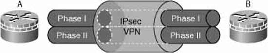
If you understand how the File Transfer Protocol (FTP) works, then you also have a good idea about how IPsec VPNs work. As with FTP, IPsec creates two security associations; one that manages the control plane (Phase I) and another which manages the data plane (Phase II).
Negotiating what? Authenticating what? No surprise that IKE Phase I is where all the separate components of the IPsec framework are negotiated between the peers. Encryption algorithms, encryption keys, HMACs, authentication method, and other parameters are negotiated between the peers. Even how to negotiate is negotiated! Once the peers agree on the parameters for the Phase I SA, the peers authenticate to one another and Phase I completes. Phase II negotiation can now occur. A good way to remember the separate IPsec policy elements, which are negotiated during Phase I, to remember the acronym HAGLE. Of course, this is a (misspelled) play on words because “haggle” is slang for negotiate and that’s what happens during Phase I.
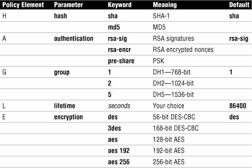
Table 7.4 explains the separate elements of the HAGLE acronym.

Exam Alert
This is an excellent memory aid. Make sure you memorize it and the choices inferred by each of the letters in HAGLE.
The IPsec policy elements in the table should look familiar by now. Let’s break down what happens during IKE Phase I a bit further by looking at a list of the negotiation and authentication tasks that IPsec uses IKE to accomplish:
![]() Automating the encryption key exchange process by:
Automating the encryption key exchange process by:
![]() Negotiating SA parameters.
Negotiating SA parameters.
![]() Automating key generation.
Automating key generation.
![]() Automating key refreshing.
Automating key refreshing.
![]() Providing for manual configuration.
Providing for manual configuration.
![]() IKE specifies three modes (in order) for negotiating parameters and establishing security associations:
IKE specifies three modes (in order) for negotiating parameters and establishing security associations:
![]() Main mode (MM): Negotiating IKE Phase I SA (see the following note).
Main mode (MM): Negotiating IKE Phase I SA (see the following note).
![]() Aggressive mode (AM): Negotiating IKE Phase I (see the following note).
Aggressive mode (AM): Negotiating IKE Phase I (see the following note).
![]() Quick mode (QM): Negotiating IKE Phase II.
Quick mode (QM): Negotiating IKE Phase II.
Note
As was pointed out a bit earlier, IKE is responsible for determining the rules that will be followed during negotiation. Main mode and aggressive mode are two different protocols for negotiating Phase I parameters and leading to the forming of a IKE Phase I SA. They are like Robert’s Rules of Order for IPsec. One or the other is chosen at the beginning of IKE Phase I negotiation and establishes the rules that subsequent negotiation are bound to follow.
Some vendors conduct their own, proprietary, exchanges after MM or AM complete. Cisco’s Mode Configuration, which is used with Easy VPN, is an example of this. This is outside the scope of this Exam Cram.
Note
As its name implies, aggressive mode specifies fewer exchanges than main mode. Each exchange has fewer packets so more negotiating is done in a shorter timeframe that equates to more efficiency. The security tradeoff is that aggressive mode is considered less secure than main mode by some security experts.
Figure 7.5 diagrams a main mode exchange between two VPN peers, Peer A and B, which in this example are both IOS VPN routers.
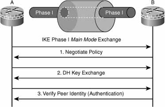
As can be seen, main mode uses three two-way exchanges:
![]() Exchange One. VPN peers propose and agree upon encryption algorithms, authentication method, and HMACs that will be used to secure subsequent IKE communications. This is where HAGLE occurs. The elements of HAGLE are called policy sets.
Exchange One. VPN peers propose and agree upon encryption algorithms, authentication method, and HMACs that will be used to secure subsequent IKE communications. This is where HAGLE occurs. The elements of HAGLE are called policy sets.
![]() Exchange Two. VPN peers employ Diffie-Hellman (DH) to create share-secret encryption keys. This share-secret encryption key is the base for generation of all other encryption and authentication keys. A secure channel (the SA) is now established.
Exchange Two. VPN peers employ Diffie-Hellman (DH) to create share-secret encryption keys. This share-secret encryption key is the base for generation of all other encryption and authentication keys. A secure channel (the SA) is now established.
![]() Exchange Three. Authentication occurs. If successful, the SA remains up; otherwise, it is torn down by the initiator.
Exchange Three. Authentication occurs. If successful, the SA remains up; otherwise, it is torn down by the initiator.
After these three exchanges complete successfully, a secure and authenticated communication path (that is, the Secure Association) is established that is used for all subsequent exchanges between the peers. It’s useful to note that exchange three is secure because the initiator will not send its own authenticators (PSK, RSA digital signature, or RSA encrypted nonce) until it has verified the responder’s.
Breaking it down a bit more, here is additional information you need to know about what happens inside main mode exchanges one and two.
The separate elements of the IKE proposals (HAGLE) are grouped in policy sets. A VPN peer may have several policy sets, numbers indicating their priority, in a policy suite. Why not just one policy set, you might ask? A single VPN peer might need several policy sets because it is configured to support several other VPNs, both site-to-site and remote-access. Each one of those other VPN peers may require a different policy set for successful VPN establishment.
One of the things agreed upon in the policy sets during exchange one was the size of the key exchange (that is, the DH groups). This is a good thing because the Diffie-Hellman key exchange results in keying “material.” The DH groups refer to the amount of keying material that results. The more keying material, the more secure (unbreakable) the encryption keys are that are generated for use with encryption algorithms.
Cisco IOS software supports four DH groups:
![]() DH Group 1 (DH1). 768 bits, usually chosen with DES encryption algorithm.
DH Group 1 (DH1). 768 bits, usually chosen with DES encryption algorithm.
![]() DH Group 2 (DH2). 1024 bits, usually chosen with 3DES encryption algorithm.
DH Group 2 (DH2). 1024 bits, usually chosen with 3DES encryption algorithm.
![]() DH Group 5 (DH5). 1536 bits, usually chosen with AES encryption algorithm.
DH Group 5 (DH5). 1536 bits, usually chosen with AES encryption algorithm.
![]() DH Group 7 (DH7). 163-bit elliptic curve cryptography (ECC), usually chosen with low CPU-powered devices such as PDAs and therefore typically only remote-access VPNs.
DH Group 7 (DH7). 163-bit elliptic curve cryptography (ECC), usually chosen with low CPU-powered devices such as PDAs and therefore typically only remote-access VPNs.
At a high level, IKE Phase II performs these functions:
![]() Negotiates IPsec Transform sets.
Negotiates IPsec Transform sets.
EXAM ALERT
Transform Sets Versus Policy Sets
IKE Phase II Encryption algorithms and HMACs are grouped in something called a transform set. Because the transform set dictates how the data is transformed through the Phase II SA, this should be easy to remember for an exam. This also implies something quite correct, which is that the encryption algorithm and HMACs in Phase II transform sets are independent (and are often different) than those negotiated in IKE Phase I policy sets.
![]() Establishes IPsec SAs (at least two; see Figure 7.6).
Establishes IPsec SAs (at least two; see Figure 7.6).

![]() Periodically renegotiates IPsec SAs.
Periodically renegotiates IPsec SAs.
![]() (Optional) Performs an additional DH key exchange.
(Optional) Performs an additional DH key exchange.
Remember that all negotiating and authentication occurs within IKE Phase I. So, where do you think IKE Phase II negotiations occur? They are conducted in the secure channel established during IKE Phase I negotiations (AM or MM) and use Quick Mode (QM). For example, during QM, policies such as the following are negotiated:
![]() Which networks will be protected by the VPN (for example, Net A’ <—> Net B’).
Which networks will be protected by the VPN (for example, Net A’ <—> Net B’).
![]() Encryption algorithm for the Phase II SA.
Encryption algorithm for the Phase II SA.
![]() HMACs.
HMACs.
![]() Transport mode versus tunnel mode (discussed in the “Transport Mode Versus Tunnel Mode” section later).
Transport mode versus tunnel mode (discussed in the “Transport Mode Versus Tunnel Mode” section later).
![]() ESP versus AH.
ESP versus AH.
Figure 7.6 depicts IKE Phase II SAs. Using the FTP analogy again, this is the data plane of the IPsec VPN and is protected by the encryption algorithms contained in the transform sets.
Interestingly, an IKE Phase II SA is unidirectional, meaning that you need two SAs for bidirectional data flow between VPN peers. This is indicated in Figure 7.6. The SAs are identified by their Security Parameter Index (SPI) numbers. For example, once the VPN was established, Peer B would have SPI AB as an inbound SPI and SPI BA as an outbound SPI in its Security Association Database (SAD).
We now examine some of IPsec’s data transport features, protocols, and algorithms.
If your VPN solution does not require confidentiality, you can choose Authentication Header (AH) alone for transport of IPsec data. AH enables you to choose algorithms to assure data integrity and data authentication but not confidentiality. No C-I-A here if you use AH alone! AH is most often used by ESP to provide for optional data integrity and data authentication and not used by itself. If AH is used by itself, AH is encapsulated in an IP packet as protocol 51.
![]() Assures data integrity.
Assures data integrity.
![]() Origin authentication (ensures that all the 1’s and 0’s came from an authenticated peer).
Origin authentication (ensures that all the 1’s and 0’s came from an authenticated peer).
![]() Uses a keyed-hash mechanism.
Uses a keyed-hash mechanism.
![]() No provision for encryption.
No provision for encryption.
![]() Anti-replay protection.
Anti-replay protection.
If your VPN solution requires confidentiality, you must choose Encapsulating Security Payload (ESP) for transport of IPsec data. As indicated previously, AH can be used with ESP to provide for data integrity and data authentication; thus covering all the letters in C-I-A. ESP is encapsulated in an IP packet as protocol 50.
ESP features are as follows:
![]() Data confidentiality through encryption.
Data confidentiality through encryption.
![]() Assures data integrity.
Assures data integrity.
![]() Origin authentication.
Origin authentication.
![]() Anti-replay protection.
Anti-replay protection.
Referring to Figure 7.7, an IP packet with source address A’ and destination address B’ arrives at peer A. Peer A applies C-I-A services to the packet as required Depending on the transform sets negotiated between the peers, not all the facets of C-I-A will be applied to the packet that will travel in the IPsec VPN between the peers. Assuming that confidentiality will be applied as a minimum, then we must use ESP for encapsulation. This also enables us to optionally apply integrity and authentication services to the packet. If you were to look at the IPsec packet on a protocol analyzer, you will see that the order of the extra fields added while encapsulating the original IP packet are C (ESP Header), I (ESP Trailer), and A (ESP Authentication Trailer) = C-I-A.

![]() C. Peer A encrypts the packet and places it into a new IP packet, prepending the encrypted payload with an ESP header. This provides for confidentiality.
C. Peer A encrypts the packet and places it into a new IP packet, prepending the encrypted payload with an ESP header. This provides for confidentiality.
![]() C and I. If integrity assurance is required, Peer A will add an integrity checksum (a hash) in the form of an ESP trailer before encrypting the original packet and placing it in the payload of the new IP packet.
C and I. If integrity assurance is required, Peer A will add an integrity checksum (a hash) in the form of an ESP trailer before encrypting the original packet and placing it in the payload of the new IP packet.
![]() C and I and A. If origin authentication is required, an authentication checksum (similar to a frame check sequence in a data link layer frame) will be added to the payload of the new IP packet but will not be encrypted.
C and I and A. If origin authentication is required, an authentication checksum (similar to a frame check sequence in a data link layer frame) will be added to the payload of the new IP packet but will not be encrypted.
The example described with Figure 7.7 uses tunnel mode. Simply put, all the original IP packet from A’ to B’ is encrypted, including the IP header where the source and destination addresses reside, before it is tunneled inside a new IP packet. Thus, we have layer 3 inside layer 3 and that equals a tunnel. The new (or outer) IP packet has the routing information necessary to route the packet across the Internet.
In some circumstances, it is either not desirable or needed to wrap the IPsec payload (either AH or ESP) inside a new IP packet. In this case, you may opt for transport mode. With transport mode, only the original IP packet’s payload (example: TCP) is encrypted, leaving the original IP header intact. If the IP addresses in the original IP packet are private, RFC 1918, addresses this might be problematic, except where the VPN between peers A and B are connected across a private intranet. There is less overhead associated with transport mode, but it isn’t very common, particularly where the VPN peers are connected across the Internet, where tunnel mode is pretty much mandatory.
We will set up an IPsec site-to-site VPN using first the CLI and then second (next section) with the Cisco SDM. Using the CLI is a very good way to demonstrate how IPsec VPNs work because manual configuration of the protocols, policies, and rules reinforces much of the theory.
The basic tasks for implementing IPsec on a site-to-site VPN using the CLI can be broken into five steps, as follows:
Step 1. Ensure that existing ACLs are compatible with the IPsec VPN.
Step 2. Create ISAKMP (IKE Phase I) policy set(s).
Step 3. Configure IPsec transform set(s).
Step 4. Create crypto ACL that defines traffic that will be in the IPsec VPN (for example, Net A’ <—-> Net B’).
Step 5. Create and apply the crypto map (IPsec tunnel interface).
Exam Alert
The missing step is Step 6: Test! That small fact aside, memorize the five steps for the exam.
Figure 7.8 illustrates the reference design for the following worked example of the steps for implementing IPsec on a site-to-site IPsec VPN using the CLI.
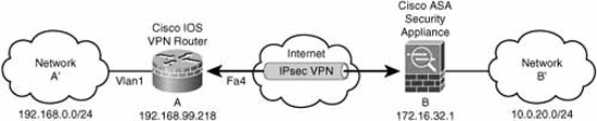
Use the commands that you learned in Chapter 5 to ensure that ISAKMP, ESP, or AH traffic will not be blocked by an existing interface ACL.
ISAKMP is the Internet Security Association Key Management Protocol and uses UDP for transport. It uses both source and destination UDP port 500. IKE messages use ISAKMP for transport. The Cisco IOS software denotes ISAKMP with keyword isakmp.
ESP is defined as IP protocol number 50. The Cisco IOS software denotes ESP with the keyword esp.
AH is defined as IP protocol number 51. The Cisco IOS software denotes ESP with the keyword ahp.
Assuming that you have an ACL 101 applied on interface FastEthernet4 on Peer A, you would need to add these lines to it in the correct place:
access-list 101 permit ahp host 172.16.32.1 host 206.248.168.15
access-list 101 permit esp host 172.16.32.1 host 206.248.168.15
access-list 101 permit udp host 172.16.32.1 host 206.248.168.15 eq isakmp
CiscoISR-A#show access-list 101
Extended IP access list 101
10 permit ahp host 172.16.32.1 host 206.248.168.15
20 permit esp host 172.16.32.1 host 206.248.168.15
30 permit udp host 172.16.32.1 host 206.248.168.15 eq isakmp
40 permit tcp any any eq 22
50 permit tcp any any eq www
60 permit tcp any any eq 443
CiscoISR#
Recall that IKE policies group all the separate elements of HAGLE into a policy set. If you need more than one IKE policy, you can create a policy suite. The crypto isakmp policy command creates the policy set. In this example, we leverage on the HAGLE acronym and create policy set 99 with the following:
H = SHA-1
A = PSK
G = DH5
L = 86,400 seconds
E = 128-bit AES
CiscoISR-A(config)#crypto isakmp policy 99
CiscoISR-A(config-isakmp)#hash sha
CiscoISR-A(config-isakmp)#authentication pre-share
CiscoISR-A(config-isakmp)#group 5
CiscoISR-A(config-isakmp)#lifetime 86400
CiscoISR-A(config-isakmp)#encryption aes
CiscoISR-A(config-isakmp)#
If we don’t need to create any more policy sets for our policy suite, we are finished with this step. You may create other policy sets, but remember that the lower the number, the higher the priority. It is good practice to put the cryptographically strongest policies near the top of the policy suite by assigning numerically lower numbers.
Also, you must ensure that the Peer B has a policy set that matches Peer A’s.
Table 7.5 shows a list of possible ISAKMP parameters when you construct a policy set. If you don’t specify a parameter, the Cisco IOS will choose the default.
In our example, we specified that we would use a PSK for authentication. Because it is possible that we may have several tunnels to the same peer, the PSK is not tied to a specific policy set. To configure a PSK, use the crypto isakmp key global configuration command. Note that the PSK is case-sensitive:
CiscoISR-A(config)#crypto isakmp key Cisc0R0ck5! Address 172.16.32.1
Alternatively, if you know the fully-qualified domain name (FQDN) of Peer B, you could type:
CiscoISR-A(config)#crypto isakmp key Cisc0R0ck5! Hostname peerB.abc.com
Note
With the crypto isakmp key command, if you use hostname or IP address to identify a VPN peer, then that peer’s configuration must identify your device using the same method.
Verify your configuration of both the ISAKMP policy set you created and the default policy set with the show crypto isakmp policy command. Effectively, you now have a policy suite with two policy sets in it: policy set 99, and the default Cisco IOS policy set.
CiscoISR-A#show crypto isakmp policy
Global IKE policy
Protection suite of priority 99
encryption algorithm: AES - Advanced Encryption Standard (128 bit keys).
hash algorithm: Secure Hash Standard
authentication method: Pre-Shared Key
Diffie-Hellman group: #5 (1536 bit)
lifetime: 86400 seconds, no volume limit
Default protection suite
encryption algorithm: DES - Data Encryption Standard (56 bit keys).
hash algorithm: Secure Hash Standard
authentication method: Rivest-Shamir-Adleman Signature
Diffie-Hellman group: #1 (768 bit)
lifetime: 86400 seconds, no volume limit
Note
The terminology in the output of the CLI command is inconsistent. What we know to be policy sets the CLI is labeling policy suites. This is incorrect, but short of asking Cisco to reengineer the CLI, we can’t change it.
Assuming we have configured a similar policy set on Peer B, the peers have all the information they need to successfully negotiate an IKE Phase I SA.
Now we configure the transform sets that will be used to protect (transform) the data in the IKE Phase II SA. Recall that transform sets are made up of an encryption algorithm and an HMAC. We create a transform set, giving it a case-sensitive name in this step. We will apply it to the policy defining the Phase II SA to Peer B in Step 5. Here are two things to remember about transform sets:
![]() A transform set is a combination of IPsec transforms that enact a security policy (transformation) for traffic.
A transform set is a combination of IPsec transforms that enact a security policy (transformation) for traffic.
![]() A transform set can have one AH transform and up to two ESP transforms
A transform set can have one AH transform and up to two ESP transforms
Use the crypto ipsec transform-set CLI command to create the transform:
CiscoISR-A(config)#crypto ipsec transform-set CantHackMe ?
ah-md5-hmac AH-HMAC-MD5 transform
ah-sha-hmac AH-HMAC-SHA transform
comp-lzs IP Compression using the LZS compression algorithm
esp-3des ESP transform using 3DES(EDE) cipher (168 bits)
esp-aes ESP transform using AES cipher
esp-des ESP transform using DES cipher (56 bits)
esp-md5-hmac ESP transform using HMAC-MD5 auth
esp-null ESP transform w/o cipher
esp-seal ESP transform using SEAL cipher (160 bits)
esp-sha-hmac ESP transform using HMAC-SHA auth
CiscoISR-A(config)#crypto ipsec transform-set CantHackMe esp-sha-hmac esp-aes 128
Recall that transforms are negotiated during QM in IKE Phase I.
Create an ACL that will define the traffic that will be transmitted inside the IPsec VPN. Of course, the ACL doesn’t do anything by itself. It will be applied to the configuration in Step 5. From Peer A’s perspective, this is any packet from the A’ network to the B’ network:
![]() Permit = Encrypt.
Permit = Encrypt.
![]() Deny = Do not encrypt.
Deny = Do not encrypt.
access-list 102 permit ip 192.168.0.0 0.0.0.255 10.0.40.0 0.0.0.255
Note
Watch those wildcard masks in the ACL. Remember that a 0 is a match bit and a 1 is an ignore bit.
Try to be as specific as possible with the crypto ACL. In our example, all IP traffic will be sent to Peer B if it is source address for the A’ network and destination address for the B’ network. If you only want VoIP traffic, for instance, to travel between the sites, say it in the ACL. Any packets that don’t match a permit statement in the ACL will be sent out of the router in cleartext.
Ensure that the crypto ACL on the other peer is symmetric with this one. Peer A’s ACL says that all IP traffic from A’ to B’ shall be in the VPN; thus, Peer B’s ACL must say the symmetric opposite. If this is not the case, VPN tunnel establishment will fail during quick mode, as this is where the policies as to what traffic is to be in the VPN are negotiated.
Conceptually, the crypto map is a virtual IPsec tunnel interface. The crypto ACL that was created in Step 4 defines the traffic that will flow into this interface toward Peer B. Here are all the elements that go into a crypto map:
![]() Crypto ACL to be used
Crypto ACL to be used
![]() Address or hostname of remote VPN peer(s)
Address or hostname of remote VPN peer(s)
![]() Transform set
Transform set
![]() Key management method (remember, this is optional in IKE Phase II)
Key management method (remember, this is optional in IKE Phase II)
![]() SA lifetime
SA lifetime
Heads up! There can be only one crypto map on a router interface. This one crypto map must support as many VPN peers, both remote-access and site-to-site as you may have to that interface. Priority numbers (just like with IKE Phase I policy sets) will group the elements together and dictate their relative priority. The lower the number, the higher the priority. Use the crypto map global configuration command to create and modify the crypto map. First, you must create the crypto map. In the following example, a crypto map called “multipurpose” is created and sequence number 999 is attached to it. Note the output from the following command, indicating that the crypto map is disabled until a peer and ACL are assigned to it:
CiscoISR-A(config)#crypto map multipurpose 999 ipsec-isakmp
% NOTE: This new crypto map will remain disabled until a peer
and a valid access list have been configured.
CiscoISR-A(config-crypto-map)#
Let’s add some parameters to sequence 999. Certainly we will want to add the transform set that we created in Step 3 and the crypto ACL that we created in Step 4. We will also want to identify the IP address or hostname of Peer B. We’ll look at an example, and then talk about some of the other parameters we can add:
CiscoISR-A(config-crypto-map)#set peer 172.16.32.1
CiscoISR-A(config-crypto-map)#set transform-set CantHackMe
CiscoISR-A(config-crypto-map)#match address 102
CiscoISR-A(config-crypto-map)#set security-association lifetime seconds 86400
CiscoISR-A(config-crypto-map)#set security-association lifetime kilobyte 4000000
CiscoISR-A(config-crypto-map)#set pfs group2
At this point, we have created the crypto map, but we must also apply it to a router interface—FastEthernet 4, in this example. Use the crypto map interface configuration mode command to do this:
CiscoISR-A(config)#interface fa4
CiscoISR-A(config-if)#crypto map multipurpose
You can verify the completeness of the crypto map and that it has been applied to the correct interface with the show crypto map CLI command:
CiscoISR-A#show crypto map
Crypto Map "multipurpose" 999 ipsec-isakmp
Peer = 172.16.32.1
Extended IP access list 102
access-list 102 permit ip 192.168.0.0 0.0.0.255 10.0.40.0 0.0.0.255
Current peer: 172.16.32.1
Security association lifetime: 4000000 kilobytes/86400 seconds
PFS (Y/N): Y
DH group: group2
Transform sets={
CantHackMe,
}
Interfaces using crypto map multipurpose:
FastEthernet4
The commands in Table 7.6 can be used to verify and troubleshoot the IPsec VPN. We have already looked at the first two while configuring the site-to-site IPsec VPN during Step 2 and Step 5, respectively.
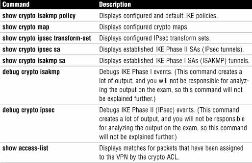
The following sections look at the output of the commands in Table 7.6 not yet examined. Look at the output and verify that it matches the reference network diagram in Figure 7.8.
This command verifies the configured IPsec transform sets. Recall that previously we created an IPsec transform set called CantHackMe with an AES 128-bit for the encryption algorithm and SHA for the HMAC:
CiscoISR-A#show crypto ipsec transform-set
Transform set CantHackMe: { esp-aes esp-sha-hmac }
will negotiate = { Tunnel, },
The show crypto ipsec sa command is used to verify the operation of the IKE Phase II data tunnels. The following command output is from Peer A’s perspective. Among other things, it can verify the following:
![]() The inbound and outbound Security Parameter Indices (SPIs) in Peer A’s Security Association Database (SAD).
The inbound and outbound Security Parameter Indices (SPIs) in Peer A’s Security Association Database (SAD).
![]() The type of IKE Phase II SAs created (ESP, AH, or other).
The type of IKE Phase II SAs created (ESP, AH, or other).
Note
The following output was captured from a Cisco ISR that was behind a NAT router and connecting to a Cisco ASA 5505 security appliance with a public IP address and that was not behind a NAT router. The two VPN devices negotiated RFC-compliant NAT Traversal (NAT-T), which wraps IKE Phase II’s ESP inside a UDP port 4500 wrapper so that it will traverse what might be a Port Address Translation (PAT) router. This is because PAT cannot tolerate stateless, portless ESP without a bit of help! This will not be on the exam, but it helps explain some of the parameters you see in the output. For example, the inbound SA’s in use settings include this pearl:
in use settings ={Tunnel UDP-Encaps, }
This indicates that the peers have negotiated tunnel mode (versus transport mode) for IKE Phase II but inside a UDP wrapper.
Refer to the following command output. The shaded output indicates the following things that we can observe:
![]() The IKE Phase II SAs are formed between local peer, Peer A (192.168.99.218), and remote peer, Peer B (172.16.32.1).
The IKE Phase II SAs are formed between local peer, Peer A (192.168.99.218), and remote peer, Peer B (172.16.32.1).
![]() The transform set applied to both the outbound and inbound IKE Phase II IPsec VPN SAs is the contains esp-aes and esp-sha-hmac as the encryption algorithm and HMAC, respectively.
The transform set applied to both the outbound and inbound IKE Phase II IPsec VPN SAs is the contains esp-aes and esp-sha-hmac as the encryption algorithm and HMAC, respectively.
![]() The IKE Phase II SAs are being encrypted and decrypted using onboard hardware acceleration (Motorola processor on this Cisco 871 ISR).
The IKE Phase II SAs are being encrypted and decrypted using onboard hardware acceleration (Motorola processor on this Cisco 871 ISR).
![]() Both inbound and outbound IKE Phase II IPsec VPN SAs are active.
Both inbound and outbound IKE Phase II IPsec VPN SAs are active.
![]() All traffic between 192.168.0.0/24 and 10.0.20.0/24 is being protected in the VPN.
All traffic between 192.168.0.0/24 and 10.0.20.0/24 is being protected in the VPN.
CiscoISR-A#show crypto ipsec sa
interface: FastEthernet4
Crypto map tag: multipurpose, local addr 192.168.99.218
protected vrf: (none)
local ident (addr/mask/prot/port): (192.168.0.0/255.255.255.0/0/0)
remote ident (addr/mask/prot/port): (10.0.20.0/255.255.255.0/0/0)
current_peer 172.16.32.1 port 4500
PERMIT, flags={origin_is_acl,}
#pkts encaps: 3, #pkts encrypt: 3, #pkts digest: 3
#pkts decaps: 3, #pkts decrypt: 3, #pkts verify: 3
#pkts compressed: 0, #pkts decompressed: 0
#pkts not compressed: 0, #pkts compr. failed: 0
#pkts not decompressed: 0, #pkts decompress failed: 0
#send errors 13, #recv errors 0
local crypto endpt.: 192.168.99.218, remote crypto endpt.:
172.16.32.1
path mtu 1500, ip mtu 1500, ip mtu idb FastEthernet4
current outbound spi: 0xBB1E0DBD(3139308989)
inbound esp sas:
spi: 0x9D5D2EC7(2640129735)
transform: esp-aes esp-sha-hmac ,
in use settings ={Tunnel UDP-Encaps, }
conn id: 1, flow_id: Motorola SEC 1.0:1, crypto map: multipurpose
sa timing: remaining key lifetime (k/sec): (3843604/27899)
IV size: 16 bytes
replay detection support: Y
Status: ACTIVE
inbound ah sas:
inbound pcp sas:
outbound esp sas:
spi: 0xBB1E0DBD(3139308989)
transform: esp-aes esp-sha-hmac ,
in use settings ={Tunnel UDP-Encaps, }
conn id: 2, flow_id: Motorola SEC 1.0:2, crypto map: multipurpose
sa timing: remaining key lifetime (k/sec): (3843604/27896)
IV size: 16 bytes
replay detection support: Y
Status: ACTIVE
outbound ah sas:
outbound pcp sas:
Look at the output of the show crypto isakmpsa command. Note that the tunnel is in a state QM_IDLE indicating that quick mode (QM) completed successfully and is currently in an idle state.
CiscoISR-A#show crypto isakmp sa
IPv4 Crypto ISAKMP SA
dst src state conn-id slot status
172.16.32.1 192.168.99.218 QM_IDLE 2005 0 ACTIVE
IPv6 Crypto ISAKMP SA
ACL 102 defines the traffic that is supposed to be in the IPsec VPN. Note that there are 19 matches, indicating that traffic is flowing into the VPN subject to the policy defined in the ACL.
CiscoISR-A#show access-list 102
Extended IP access list 102
10 permit ip 192.168.0.0 0.0.0.255 10.0.20.0 0.0.0.255 (19 matches)
Configuring a site-to-site VPN with the SDM should be fairly straightforward, now that we have examined the fundamentals of how IPsec VPNs work and grounded the theory by configuring a site-to-site IPsec VPN with the CLI.
When using the SDM to configure a site-to-site IPsec VPN, you can either manually configure the VPN or employ the Cisco SDM VPN Wizard. We will choose the wizard and see that the wizard will give us a choice of the following:
![]() Quick setup. Uses pre-built settings (useful for a brand-new VPN configuration with another Cisco IOS router that is being configured with the quick setup versus the step-by-step wizard).
Quick setup. Uses pre-built settings (useful for a brand-new VPN configuration with another Cisco IOS router that is being configured with the quick setup versus the step-by-step wizard).
![]() Step-by-step wizard. For more granular, detailed configuration control.
Step-by-step wizard. For more granular, detailed configuration control.
Let’s look at these two wizards, one at a time.
To launch the Site-to-Site VPN Wizard and enter Quick Setup, complete the following steps:
-
Navigate to Configure->VPN in the SDM.
-
Select Site-to-Site VPN from the left navigation pane.
-
Make sure that the Create Site to Site VPN tab is selected in the main navigation window.
-
Check the Create a Site to Site VPN radio button, as indicated in Figure 7.9.
-
Press the Launch the selected task button. The Site-to-Site VPN Wizard window appears.
-
Note the choices indicated in Figure 7.10. You can choose either Quick setup or Step by step wizard. Press the Quick setup radio button; then click Next. A window appears in which you can enter some basic information about the VPN. Note that it doesn’t ask you what encryption algorithms, hashes, or DH groups you want to use.
-
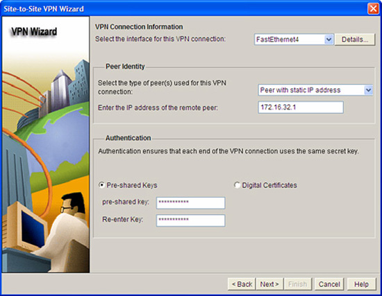
The VPN Connection Information window pops up, as indicated in Figure 7.11. Look at this window while referring to the reference network diagram in Figure 7.8. We know exactly what to fill in. From top to bottom:
VPN Connection Information:


![]() Select the interface for this VPN connection: FastEthernet4.
Select the interface for this VPN connection: FastEthernet4.
![]() Select the type of peer(s) used for this VPN connection: Peer with static IP address.
Select the type of peer(s) used for this VPN connection: Peer with static IP address.
![]() Enter the IP address of the remote peer: 172.16.32.1.
Enter the IP address of the remote peer: 172.16.32.1.
Authentication:
![]() Pre-Shared Keys or Digital Certificates radio button: Press the Pre-shared keys radio button. Fill in the pre-shared key in the pre-shared key and Re-enter key fields.
Pre-Shared Keys or Digital Certificates radio button: Press the Pre-shared keys radio button. Fill in the pre-shared key in the pre-shared key and Re-enter key fields.
![]() Source: Choose Vlan1 as the source interface in the drop-down list. This is the interface that the net A’ to net B’ traffic will arrive on.
Source: Choose Vlan1 as the source interface in the drop-down list. This is the interface that the net A’ to net B’ traffic will arrive on.
![]() Destination: Enter 10.0.20.0 in the IP Address field and 255.255.255.0 in the Subnet Mask field. (Alternatively, you can put the number of bits (24) in the “or” field.)
Destination: Enter 10.0.20.0 in the IP Address field and 255.255.255.0 in the Subnet Mask field. (Alternatively, you can put the number of bits (24) in the “or” field.)

8. Click Finish. The Summary of the Configuration window appears. It will look something like Figure 7.12.

If you don’t like the IKE policies and IPsec transform sets that are created for you, then Quick Setup is not a good choice. Chances are good that 3DES for a cipher for both Phase I and Phase II will not match the organization’s comprehensive network security policy. Here are the parameters selected by the SDM when using Quick Setup:
IKE Policy Set (HAGLE):
H = SHA-1
A = PSK
G = DH2
L = 86,400 (default, since doesn’t appear)
E = 3DES
IPsecTransform Set:
Transport = ESP
Tunnel Mode
Encryption = 3DES
Hash = SHA-1
9. If you like what you see, click on Finish to deliver the commands to the router. You might have noticed the Test VPN connectivity after configuring check box. We examine this feature when we (next) configure the VPN with the SDM Site-to-Site VPN Wizard, but choosing step-by-step this time.
The five tasks of the wizard using Step-by-Step setup are as follows:
Task 1: Define Connection Settings:
![]() Outside interface
Outside interface
![]() Peer address
Peer address
![]() Authentication credentials
Authentication credentials
Task 2: Define IKE Proposals:
![]() Priority
Priority
![]() Encryption algorithm
Encryption algorithm
![]() HMAC
HMAC
![]() Mode of operation (AM, MM)
Mode of operation (AM, MM)
Task 3: Define IPsec Transform Sets:
![]() Encryption algorithm
Encryption algorithm
![]() HMAC
HMAC
![]() Mode of operation (tunnel, transport)
Mode of operation (tunnel, transport)
![]() Compression
Compression
Task 4: Define Traffic to Protect (Crypto ACL):
![]() Single source and destination subnets
Single source and destination subnets
or
![]() Create ACL (can use existing if already created)
Create ACL (can use existing if already created)
Task 5: Review and Complete the Configuration
To begin the step-by-step setup of the Cisco SDM Site-to-Site VPN Wizard:
-
Navigate to Configure->VPN and select Site-to-Site VPN in the list box on the left side.
-
Ensure the Create Site to Site VPN tab is selected and push the Create a Site to Site VPN radio button.
-
Click the Launch the selected task button. The Site-to-Site VPN Wizard window appears, as indicated in Figure 7.13.
-
Push the Step by step wizard radio button and click the Next button. A window appears, prompting you to define the connection settings.
Follow these steps to define basic connection settings:
-
Fill in the information per the reference diagram in Figure 7.8. If this was the real world, you would have all this information at your fingertips as part of a well-executed security policy.
-
Click Next. A window appears, as indicated in Figure 7.14, prompting you to define an IKE proposal for the site-to-site VPN.
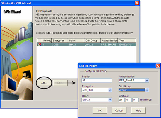
The next step is to define the IKE proposals to be used. You can use either the built-in, default proposal or create your own. Follow these steps to define the IKE proposal:
-
The list of IKE proposals will have at least the SDM default (look under the Type column). Click Add and the Add IKE Policy window appears.
-
Fill in the information for the IKE proposal using the HAGLE values that you have already determined. In this example, we are creating an IKE proposal with these parameters:
![]() Priority: 99
Priority: 99
![]() Authentication: PRE_SHARE
Authentication: PRE_SHARE
![]() Encryption: AES_128
Encryption: AES_128
![]() D-H Group: group5
D-H Group: group5
![]() Hash: SHA_1
Hash: SHA_1
![]() Lifetime: 24:00:00 (HH:MM:SS)
Lifetime: 24:00:00 (HH:MM:SS)
3. Click OK when finished. The IKE proposal appears highlighted in the list of IKE proposals. Leave it selected and click Next. A window appears, as indicated in Figure 7.15, prompting you to define an IPsec transform set for the site-to-site VPN.

Follow these steps to define an IPsec transform set for use in the site-to-site VPN:
-
The list of IPsec transform sets will have at least the SDM default (selected in the Select Transform Set drop-down list). Click Add, and the Add Transform Set window appears. Click the Show Advanced button to reveal advanced options.
-
Fill in the information for the IPsec transform set. Because we have selected the advanced options, we can verify that:
 The Tunnel radio button is selected in the Mode section of the advanced options. The Data and address integrity without encryption (AH) box is unchecked. The IP Compression (COMP-LZS) box is unchecked.
We will fill in the following parameters:
Name: CantHackMe Data Integrity with encryption (ESP): checked Integrity Algorithm: ESP_SHA_HMAC Encryption Algorithm: ESP_AES_128
3. Click OK. The transform set we just added appears highlighted in the Transform Set window. Leave it selected; then click Next. A new window appears, as indicated in Figure 7.16, prompting you to define the traffic to protect in the site-to-site VPN.

Follow these steps to define the traffic that will be protected by the VPN. These steps create a crypto ACL:
-
Fill out the IP address and subnet mask of the local and remote networks that will be protected by the site-to-site VPN. Alternatively, if you already have an ACL created or want to create an ACL for this purpose, you can press the Create/Select an access-list for IPSec traffic radio button and follow the prompts. In this example, we press the Protect all traffic between the following subnets radio button and fill out the following information:
IP Address: 192.168.0.0 Subnet Mask: 255.255.255.0Remote Network:
IP Address: 10.0.20.0 Subnet Mask: 255.255.255.0
2. Click Next. The Summary of the Configuration window appears, as indicated in Figure 7.17.
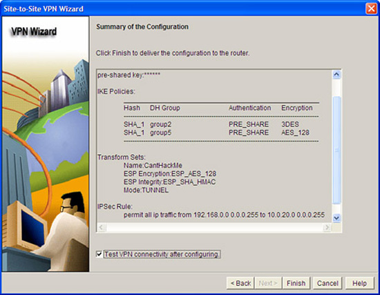
Follow these steps to review and complete the configuration:
-
We’re almost done. Review the information in the Summary of the Configuration window. Note that this VPN peer will propose two IKE policy sets: the SDM default, and the one we created earlier in the wizard. For IKE Phase II, it will propose only the IPsec transform set that we created in task 3.
-
Check the Test VPN connectivity after configuring box because we will want to test the VPN when we are finished.
-
Click OK. Because we indicated that we wanted to test the VPN, the VPN Troubleshooting window appears, as shown in Figure 7.18. Verify under Tunnel Details at the top of this window that the interface that we are using to connect to our VPN peer appears beside the Interface section.
-
Click Start to initiate the test.
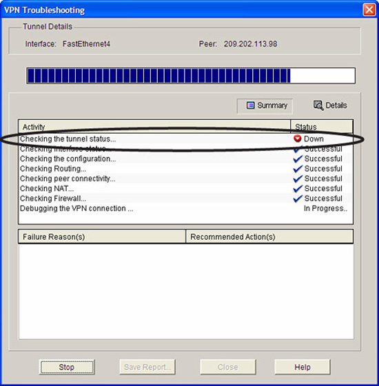
Note
Don’t be surprised if the tunnel doesn’t come up during the test because there is no reason for the tunnel to be constructed unless traffic is generated from the A’ to B’ networks. This is indicated in Figure 7.18, where the first step, “Checking the tunnel status...” fails. If this occurs, the SDM will prompt you to allow either the SDM or you to generate traffic to attempt to bring up the VPN. Figure 7.19 shows this dialog preceded by a warning (that we have to click through) written by Cisco’s lawyers that indicates that generating the traffic may create router performance issues.
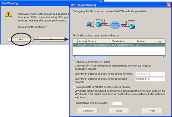
If the VPN fails and you have generated traffic to bring up the VPN as a troubleshooting step (see the previous note), then the VPN should come up as indicated in Figure 7.20.

For more advanced troubleshooting, Cisco recommends using the CLI commands covered in the section, “Table 7.6.