
The first thing you need to know is that cryptology and cryptography are not the same things. Cryptology is the overall art and science of making and breaking codes. Cryptography and cryptanalysis are disciplines within cryptology.
Note
The second thing you need to know is that in attempting to define any one term in the field of cryptology, a floodgate of other new terminology, many starting with the letter “c,” is opened!
Here are some basic definitions of words that start with “crypt”:
Cryptography. Code making. It is the art of creating and using simple word or character substitutions to hide the original meaning.
![]() Cryptanalysis. Code breaking. It is the process of analyzing a cryptographic algorithm for weaknesses and exploiting them to break the code.
Cryptanalysis. Code breaking. It is the process of analyzing a cryptographic algorithm for weaknesses and exploiting them to break the code.
![]() Cryptosystem. Any system that implements codes to encrypt and decrypt messages.
Cryptosystem. Any system that implements codes to encrypt and decrypt messages.
![]() Cipher. A cryptographic algorithm (or “encryption algorithm”) used to encrypt and decrypt files and messages.
Cipher. A cryptographic algorithm (or “encryption algorithm”) used to encrypt and decrypt files and messages.
![]() Ciphertext. An encrypted message or file. Code.
Ciphertext. An encrypted message or file. Code.
![]() Cleartext (or plaintext). An unencrypted message or file.
Cleartext (or plaintext). An unencrypted message or file.
![]() Encryption (Enciphering). Cryptosystems encrypt by rendering cleartext into ciphertext. Encoding.
Encryption (Enciphering). Cryptosystems encrypt by rendering cleartext into ciphertext. Encoding.
![]() Decryption (Deciphering). The message recipient’s cryptosystem decrypts by rendering the ciphertext back into cleartext. Decoding.
Decryption (Deciphering). The message recipient’s cryptosystem decrypts by rendering the ciphertext back into cleartext. Decoding.
Note
The terms enciphering and deciphering, while technically accurate, are not commonly used anymore.
Let’s talk about a common misuse of terminology. There is no such action as unencryption because there is no verb “unencrypt.” Encrypted messages are decrypted, not unencrypted, by a cryptosystem. Unencrypted is an adjective that refers to a message that is sent in cleartext.
An example of a real-time use of cryptology would be an IPsec VPN cryptosystem, which uses cryptographic algorithms (ciphers) to encrypt messages into ciphertext and decrypt those same messages back to cleartext. A cryptanalyst (a hacker, for example) would use the science of cryptanalysis as a form of man-in-the-middle attack to try to break the code. There, we’ve used all the terms in the list of definitions that we’ve created so far!
Figure 6.1 illustrates the elements of a cryptosystem. The data flow is left to right. All the traffic from the A network to the B network is encrypted by router A and becomes ciphertext for transmission inside an IPsec VPN to router B. Attackers (cryptanalysts!) would not be able to read the ciphertext because they possess neither the encryption key nor the encryption algorithm, both of which would be needed to decrypt this coded transmission. When the ciphertext arrives at router B, it is decrypted using the same encryption algorithm and encryption keys as were used by router A to encrypt it. When the message is forwarded by router B to network B, its final destination, it has been rendered back into cleartext.

Theoretically, it is possible to break any code because an attacker would only need to try by brute force every possible key (a large universe of possibilities) in combination with all known ciphers (a small universe of possibilities). The emphasis, of course, is on the word theoretical. Part of the art of encryption in a Cisco network, or any network security architecture, is to find the balance between usability and security. In this case, the encryption algorithms may be well known and therefore guessable, but we must make the keys reasonably difficult to break such that a knowledgeable attacker cannot access our sensitive information. You can read the specifics of how to implement an IPsec VPN cryptosystem in Chapter 7, but it would be useful to look at some of the building blocks first.
Exam Alert
Understanding the fundamentals of a cryptosystem at a high level will aid you greatly in understanding, rather than simply memorizing, the concepts. In turn, you will find it much easier to configure the crypto features of the Cisco IOS, including IPsec VPNs. If that isn’t motivation enough, troubleshooting issues that deal with cryptography requires a high-level understanding at a minimum.
Historically, earlier efforts in creating cryptosystems relied on the secrecy of the cipher itself to achieve confidentiality. Examples of this would be the Caesar cipher or the Enigma machine used by the German military during World War II. With most modern cryptosystems, secrecy relies on the strength of the keys because knowledge of the crypto algorithms themselves is largely in the public domain.
We hadn’t used the term key until the last two paragraphs. Basically, there are two main elements in a cryptosystem that are used to turn cleartext into ciphertext: ciphers, defined earlier, and keys. A key (also known as an encryption key or cryptographic key) is a collection of bits, usually stored in a file, that are used with a cipher to encrypt and decrypt a message.
Fair to say, the larger the number of bits in your bit collection, the stronger the resulting encryption. There is more about keys in the sections “Exploring Symmetric Key Encryption” and “Exploring Asymmetric Key Encryption and Public Key Infrastructure” later in this chapter.
To place all this into a networking context, encryption can occur at several layers of the OSI model, including the following:
![]() Data Link Layer (OSI Layer 2). Proprietary link layer encryption devices; examples include Ethernet NICs with encryption chips, which encrypt the payload of frames.
Data Link Layer (OSI Layer 2). Proprietary link layer encryption devices; examples include Ethernet NICs with encryption chips, which encrypt the payload of frames.
![]() Network Layer (OSI Layer 3). Protocols such as the IPsec framework, which create encrypted payload in network layer packets.
Network Layer (OSI Layer 3). Protocols such as the IPsec framework, which create encrypted payload in network layer packets.
![]() Transport Layer (OSI Layer 4). Protocols such as Transport Layer Security (TLS) and Secure Sockets Layer (SSL), which create encrypted payload in transport layer segments.
Transport Layer (OSI Layer 4). Protocols such as Transport Layer Security (TLS) and Secure Sockets Layer (SSL), which create encrypted payload in transport layer segments.
![]() Application Layer (OSI Layers 5–7). Protocols such as Microsoft’s Remote Desktop Protocol (RDP) for remote terminal sessions or secure messaging applications, such as Lotus Notes, and secure database applications, such as Oracle’s SQL*Net, which create encrypted payload at the application layer.
Application Layer (OSI Layers 5–7). Protocols such as Microsoft’s Remote Desktop Protocol (RDP) for remote terminal sessions or secure messaging applications, such as Lotus Notes, and secure database applications, such as Oracle’s SQL*Net, which create encrypted payload at the application layer.
Note
There are examples of both IPsec and SSL in Chapter 7 because they are useful in setting up the vendor-neutral, real-time network cryptosystems called virtual private networks (VPNs).
It’s a question of perspective. If you’re a hacker, you’re not attacking, you’re cryptanalyzing, right? At least, that’s what you tell the judge. If you are the victim, it’s a cryptographic attack. Table 6.1 explains some examples of cryptographic attacks.


Note
You may recall from Chapter 2, “Building a Secure Network Using Security Controls,” that encryption, and thus cryptosystems, are examples of technical controls. The organization’s security policy will dictate what constitutes “reasonable security,” hopefully after using industry-standard metrics to measure the organization’s vulnerability to the threat of certain exploits. Physical controls must be defined and implemented to safeguard the technical controls.
In January of 1999, the Data Encryption Standard (DES) cipher developed by IBM, and which uses 56-bit keys, was cracked in just over 22 hours as part of the RSA Data Security’s “DES Challenge III” (see http://www.networkworld.com/news/1999/0120cracked.html).
It is estimated that using the same method, the Advanced Encryption Standard (AES) could be cracked in 149 trillion years.
A good encryption algorithm should be resistant to the attacks outlined in Table 6.1. Table 6.2 lists other key features desirable in an encryption algorithm.

Encryption keys work with encryption algorithms to turn cleartext into ciphertext. But be careful with our terminology because it isn’t the keys that are symmetric or asymmetric; it is the method in which they are used by encryption algorithms that determines their symmetry. There are two broad categories of use for encryption keys:
![]() Symmetric Encryption Algorithm. Uses the same key to encrypt and decrypt data.
Symmetric Encryption Algorithm. Uses the same key to encrypt and decrypt data.
![]() Asymmetric Encryption Algorithm. Requires different keys—one key to encrypt the cleartext, and another to decrypt the ciphertext.
Asymmetric Encryption Algorithm. Requires different keys—one key to encrypt the cleartext, and another to decrypt the ciphertext.
Complete sections later in this chapter explore examples of each in more detail.
Note
“I want examples!” you say. OK, here’s one. As was noted earlier, since the focus on modern cryptosystems is the strength of the encryption key, safeguarding the key is of primary importance. A related issue is key distribution. For example, if the modern cryptosystem is an IPsec VPN using symmetric keys, generating a shared secret key for encryption between two VPN gateways over a hostile network such as the Internet is a critical issue. For example, the keys could be distributed out-of-band using a courier service or a phone call and then manually inputted on the devices. This is probably secure but hardly convenient. The Diffie-Hellman (DH) key exchange solves this issue. It defines an in-band (and slightly magical!) way of securely creating a shared key using the same hostile network that the data will eventually be encrypted and transmitted across. This is explained in Chapter 7.
Because symmetric key algorithms are based on simple mathematical operations, they are quite fast and often used for encryption services; they are easily accelerated by hardware. We will see examples of hardware acceleration in Cisco hardware in Chapter 7.
Key management algorithms, such as Diffie-Hellman mentioned in the previous note, provide secure key exchange. Examples of symmetric key algorithms and their key lengths include the following:
![]() DES (Data Encryption Standard). 56 bits.
DES (Data Encryption Standard). 56 bits.
![]() 3DES (Triple DES). 112 and 168 bits.
3DES (Triple DES). 112 and 168 bits.
![]() AES (Advanced Encryption Standard). 128, 192, and 256 bits.
AES (Advanced Encryption Standard). 128, 192, and 256 bits.
![]() IDEA (International Data Encryption Algorithm). 128 bits.
IDEA (International Data Encryption Algorithm). 128 bits.
![]() RC (Rivest Cipher or Ron’s Code) Series:
RC (Rivest Cipher or Ron’s Code) Series:
![]() RC2: 40 and 64 bits.
RC2: 40 and 64 bits.
![]() RC4: 1 to 256 bits.
RC4: 1 to 256 bits.
![]() RC5: 0 to 2040 bits.
RC5: 0 to 2040 bits.
![]() RC6: 128, 192, and 256 bits.
RC6: 128, 192, and 256 bits.
![]() Blowfish. 32 to 448 bits.
Blowfish. 32 to 448 bits.
![]() SEAL (Software Encryption Algorithm). 160 bits.
SEAL (Software Encryption Algorithm). 160 bits.
Exam Alert
Know the names of all the ciphers in the previous list, as well as the key length that they each require.
Note
AES, also known as Rijndael after the last names of the co-inventors, resulted from a competition by the National Institute of Standards and Technology (NIST) for a successor to the pervasive DES cipher. RC6 was one of the finalists in that same competition. AES was adopted in November 2001 and approved by NIST as FIPS 197. It is remarkable for its speed, relative ease of use, and little memory requirement. Since its adoption, it has quickly become the de facto standard for encryption worldwide and not just for the U.S. federal government.
Asymmetric key algorithms are more commonly referred to as public key algorithms. For example, in an IPsec VPN, a device such as an IOS router will use its peer’s public key to encrypt data to that peer and decrypt data from that same peer using its own private key. The asymmetry is found in the fact that each peer requires a key pair consisting of a private key and public key. The private key is almost never transmitted to the peer, but the public key can be freely exchanged because only the holder of the matching private key will be able to decrypt messages encrypted with that public key. This makes the resulting cryptosystem highly resistant to attacks ... assuming that a key of sufficient length and complexity is chosen of course.
Examples of encryption algorithms that make use of asymmetric keys (usually in lengths of 512 to 4096 bits) include the following:
![]() Diffie-Hellman (DH)
Diffie-Hellman (DH)
![]() Rivest Shamir Adleman (RSA)
Rivest Shamir Adleman (RSA)
![]() Elliptic Curves Cryptography (ECC)
Elliptic Curves Cryptography (ECC)
![]() ElGamal Encryption System (ElGamal)
ElGamal Encryption System (ElGamal)
Asymmetric encryption algorithms are slower than symmetric encryption algorithms because they are based on complex computations.
Also, the lengths of the encryption keys, while longer than symmetric keys, do not equate to equivalent security bit-to-bit, according to the following key equivalency:
![]() RSA with 1024-bit key equal to 80-bit symmetric key
RSA with 1024-bit key equal to 80-bit symmetric key
![]() RSA with 2048-bit key equal to 112-bit symmetric key
RSA with 2048-bit key equal to 112-bit symmetric key
![]() RSA with 3072-bit key equal to 128-bit symmetric key
RSA with 3072-bit key equal to 128-bit symmetric key
Now that we’ve categorized encryption algorithms by their use of keys (symmetric or asymmetric), let’s look at categorizing ciphers by the way they organize data prior to encryption. Encryption algorithms can be either block ciphers or stream ciphers.
Block ciphers have the following characteristics:
![]() A data stream is parsed into fixed-length units (blocks) of plaintext data and then transformed into ciphertext of the same length.
A data stream is parsed into fixed-length units (blocks) of plaintext data and then transformed into ciphertext of the same length.
![]() The size of the block used varies with the cipher (DES uses 8 bytes = 64 bits).
The size of the block used varies with the cipher (DES uses 8 bytes = 64 bits).
![]() Block sizes have to be uniform so padding is common.
Block sizes have to be uniform so padding is common.
![]() The resulting ciphertext is typically longer than the plaintext (see the last bullet in the following stream cipher characteristics list for comparison).
The resulting ciphertext is typically longer than the plaintext (see the last bullet in the following stream cipher characteristics list for comparison).
Stream ciphers have the following characteristics:
![]() Stream ciphers work at a more granular level, using smaller units of plaintext data; bits, for example.
Stream ciphers work at a more granular level, using smaller units of plaintext data; bits, for example.
![]() Because blocking is not used, padding is not needed, and therefore the size of the messages does not change when they are transformed to ciphertext.
Because blocking is not used, padding is not needed, and therefore the size of the messages does not change when they are transformed to ciphertext.
Note
Do not confuse the number of bits in a block used by a block cipher with the number of bits in its key. For example, 3DES uses a 168-bit key, but 64-bit blocks.
Stream ciphers can be much faster than block ciphers because they do not need to block and pad the data and can encrypt an arbitrary number of bits.
Common block ciphers include the following:
![]() DES and 3DES when used in Electronic Code Book (ECB) or Cipher Block Chaining (CBC) mode
DES and 3DES when used in Electronic Code Book (ECB) or Cipher Block Chaining (CBC) mode
![]() AES
AES
![]() IDEA
IDEA
![]() Secure and Fast Encryption Routine (SAFER)
Secure and Fast Encryption Routine (SAFER)
![]() Skipjack
Skipjack
![]() Blowfish
Blowfish
![]() RSA
RSA
Common stream ciphers include the following:
![]() DES and 3DES when used in Output Feedback (OFB) or cipher feedback (CFB) mode
DES and 3DES when used in Output Feedback (OFB) or cipher feedback (CFB) mode
![]() RC4
RC4
![]() Software Encryption Algorithm (SEAL)
Software Encryption Algorithm (SEAL)
We’ve categorized encryption algorithms by whether they use block or stream ciphers and whether they use symmetric or asymmetric keys. At a high level, we have looked at some of the features of these categories. This still doesn’t answer the over-arching question as to which encryption algorithm we should choose. Is there a body of industry best practices that will help? According to Cisco, it is a matter of trust and an algorithm’s resistance to brute force attack.
Two basic criteria for choosing an encryption algorithm are as follows:
![]() The algorithm provides sufficient protection against brute force attacks. (For more about who defines “sufficient,” see Chapter 2 and the following note.)
The algorithm provides sufficient protection against brute force attacks. (For more about who defines “sufficient,” see Chapter 2 and the following note.)
![]() The algorithm is trusted by the greater cryptographic community.
The algorithm is trusted by the greater cryptographic community.
With respect to the last point, symmetric algorithms that are considered trusted are DES, 3DES, IDEA, RC4, and AES.
Asymmetric algorithms that are considered trusted are RSA and DH.
Note
Practically speaking, the organization’s security policy will determine whether a cipher provides sufficient protection against attack based on such factors as the likelihood of an exploit and the cryptosystem’s vulnerability against specific threats. One would think that the most secure cipher should always be the one to choose, as long as it doesn’t introduce unacceptable tradeoffs in terms of performance and latency. In reality, it is the trustworthiness and not just the security of a cipher that may tip the balance when deciding the cipher to use in a cryptosystem such as an IPsec VPN. Trust is hard to quantify, but the idea of trust is easier to quantify with industry data. For example, because they are trusted by industry, an IPsec VPN might be configured to use the following:
![]() AES as a symmetric algorithm for protecting data and the negotiations between the peers.
AES as a symmetric algorithm for protecting data and the negotiations between the peers.
![]() DH for automating the generation and exchange of encryption keys between the peers.
DH for automating the generation and exchange of encryption keys between the peers.
Other encryption algorithms might not be trusted. For example, ECC is considered to be relatively immature. However, depending on the cryptosystem’s requirements, it might be an acceptable tradeoff, especially if the devices in the cryptosystem do not possess much processing power.
A cryptographic hash is sometimes described as a one-way encryption—encryption where there is no possibility of decryption. Hashing algorithms, like encryption algorithms, take cleartext data and using an encryption key, transform the cleartext data into something different and unreadable by an attacker. But what comes out of the hashing process is not ciphertext as with encryption algorithms, but rather a fixed-length hash. The implication with ciphertext is that it will be deciphered. With a hash, the whole purpose is that it cannot be deciphered.
Hashes are most commonly used as a method of integrity assurance. (Recall C-I-A from Chapter 1.) When a device in a cryptosystem wants to ensure that the data that it is sending to its peer is not being tampered with, it can append a hash of a message with the original message. The receiving device can create its own hash of the received message and compare it with the hash that is appended to the message. If they are the same, then the message has not been tampered with.
What prevents an attacker from altering a message and then altering the hash to reflect the altered message’s new contents? Nothing actually, except both the sender and the receiver are not only using the same hashing algorithm, but they are hashing the message with a shared secret key added. Only the devices that knows the key (and they’re not sharing it with an attacker) will be able to create and compare the hashes correctly. There’s another use of keys, again underlining how important it is to properly manage and secure these keys.
Note
Hashing algorithms are described in more detail in the “Exploring Cryptographic Hashing Algorithms and Digital Signatures” section of this chapter.
A recurring thread has been the necessity of proper key management because attacks against modern cryptosystems are not against the encryption algorithms, but against the keys.
Principles of key management include the following:
![]() Key management policies describe the secure generation (or issuance), verification, exchange, storage, and destruction of keys.
Key management policies describe the secure generation (or issuance), verification, exchange, storage, and destruction of keys.
Note
Getting way ahead of ourselves for a moment, Public Key Infrastructure (PKI) is a good example of the principles of key management. PKI defines a whole protocol for the secure issuance, exchange, revocation, destruction, storage, and backup of digital certificates and integral asymmetric keys used for device and individual authentication and encryption, typically in an enterprise setting. PKI is examined later in the section, “Exploring Asymmetric Key Encryption and Public Key Infrastructure.”
![]() Key management is often considered the most difficult task of designing, implementing, and maintaining cryptosystems.
Key management is often considered the most difficult task of designing, implementing, and maintaining cryptosystems.
![]() Secure key management is vitally important in a cryptosystem.
Secure key management is vitally important in a cryptosystem.
![]() Compared to encryption algorithms, key management is a more common avenue of attack on modern cryptosystems.
Compared to encryption algorithms, key management is a more common avenue of attack on modern cryptosystems.
Following is a summary of the component tasks in a key management policy. A key management policy manages key:
![]() Generation
Generation
![]() Verification
Verification
![]() Storage
Storage
![]() Exchange
Exchange
![]() Revocation
Revocation
![]() Destruction
Destruction
Because we have established that attackers will pry away at a modern cryptosystem’s keys, it stands to reason that we should do nothing to aid the attackers in their tasks. Two considerations with respect to keys stand out: the concept of keyspaces and the issue of key length.
A keyspace is the set of all possible values that a key might draw from. This is the “universe of choices.” The larger the keyspace, the more difficult it will be for a brute force attack to be successful. An effective comprehensive network security policy will recognize these keyspace concepts:
![]() The keyspace of an encryption algorithm is the set of all possible key values.
The keyspace of an encryption algorithm is the set of all possible key values.
![]() Each bit has two possible values, 1 or 0; thus, an n-bit key has 2n possible key values.
Each bit has two possible values, 1 or 0; thus, an n-bit key has 2n possible key values.
![]() Most encryption algorithms can be configured to use weak (easily guessable and repeating) keys.
Most encryption algorithms can be configured to use weak (easily guessable and repeating) keys.
![]() Manual definition of keys can be difficult because care must be taken to avoid the use of known weak keys.
Manual definition of keys can be difficult because care must be taken to avoid the use of known weak keys.
The longer the key length, the larger the keyspace, the more difficult it is to crack the code. If an encryption algorithm is considered trustworthy (see the earlier section, “Which Encryption Algorithm Do I Choose?”), then the only way that an attacker can crack the code is by attempting to brute-force the keys. The goal is to make this kind of attack unfeasible.
Note
A largely unspoken axiom of network security is that you are making your network unattractive to attackers. The more unattractive you make your network, the more likely that an attacker will move on to another network. This is the philosophy that many people use in burglar-proofing their homes. It’s not so much that they are burglar-proof; rather, that there is often a visible deterrent that makes the burglar move on to a neighbor’s house. Remember from an earlier chapter, network security is not a risk elimination exercise; it is a risk mitigation exercise. Long keys are unfeasible to crack. A sufficiently long key with a modern cryptosystem could conceivably take millions or billions of years to crack. The sun will have exploded and the earth turned to dust by that time.
Exam Alert
On average, cryptanalysis by brute force will crack the code after searching through half the keyspace.
The length of your keys should be dictated by the tradeoff between security and usability. Knowing your attackers (including how well-funded they are) through a proper risk assessment will indicate the encryption algorithm to use and the length of encryption keys to use with that algorithm.
SSL VPNs are becoming increasingly common. SSL is also a good way to demonstrate some of the encryption algorithms, hashing algorithms, and the use of encryption keys that we have looked at so far. Chapter 7 contains a quick overview of some of Cisco’s SSL VPN solutions. Here we will do a quick overview of what SSL is and then use it to glue some of the ideas we have come across to our synapses. SSL is a cryptosystem that was invented by Netscape Corporation in the mid 1990s.
SSL characteristics include the following:
![]() Symmetric key algorithms for encryption.
Symmetric key algorithms for encryption.
![]() Asymmetric key algorithms for authentication and key exchange.
Asymmetric key algorithms for authentication and key exchange.
![]() Hashes during the authentication process. Cleartext passwords are never exchanged.
Hashes during the authentication process. Cleartext passwords are never exchanged.
![]() Similar to IPsec in that it specifies methods to negotiate encryption algorithms and then uses the negotiated algorithms to transform data.
Similar to IPsec in that it specifies methods to negotiate encryption algorithms and then uses the negotiated algorithms to transform data.
![]() Used worldwide by many e-commerce sites (at least the ones we trust!).
Used worldwide by many e-commerce sites (at least the ones we trust!).
![]() Secures not only web communication but is also popular to secure email protocols such as SMTP, FTP, IMAP, and POP3.
Secures not only web communication but is also popular to secure email protocols such as SMTP, FTP, IMAP, and POP3.
![]() Gaining rapid acceptance as an alternative to IPsec for remote-access VPNs.
Gaining rapid acceptance as an alternative to IPsec for remote-access VPNs.
![]() Transport Layer Security (TLS) is the newer, standards-based, replacement for SSL. (But we still call the whole paradigm SSL.)
Transport Layer Security (TLS) is the newer, standards-based, replacement for SSL. (But we still call the whole paradigm SSL.)
![]() Employs key lengths between 40 and 256 bits for encryption algorithms.
Employs key lengths between 40 and 256 bits for encryption algorithms.
Figure 6.2 illustrates Cisco’s new remote-access AnyConnect SSL VPN client establishing a VPN to a central site ASA 5500 Series adaptive security appliance using SSL. As noted, SSL defines methods for negotiating the ciphers, as well as authenticating the peers and performing a secure key exchange. This is the same exchange as would occur if a user were to visit a secure e-commerce site such as would be established for online banking.

Note
Step 6 in Figure 6.2 is included for the sake of completeness, however it is not part of a standard SSL tunnel establishment process.
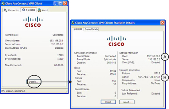
After the secure SSL tunnel is established, the VPN client obtains an IP address, subnet mask, default gateway, and other information from the VPN server, the ASA. The result is illustrated in Figure 6.3. Look for these two things on Figure 6.3:
A. The client has obtained IP address 192.168.20.8.
B. An RSA_AES_128_SHA1 cipher has been negotiated to protect the data in the VPN tunnel.
The simplest, most scalable cryptosystems to implement are those that use symmetric key encryption. Ciphers that use symmetric keys use the same key to encrypt and decrypt the data. We will examine the principles and operation of symmetric key encryption algorithms and look at examples of its implementation while weighing its strengths and weaknesses.
Figure 6.4 represents a typical symmetric key cryptosystem. The data flow is from left to right. Cleartext data is rendered into ciphertext by the sender by encrypting the data with an encryption key and a cipher. The ciphertext is turned back into cleartext when the receiver in the cryptosystem uses the same encryption algorithm with an identical key to decrypt the data.

Here are some facts about the key lengths used with symmetric key encryption algorithms:
![]() 40 to 256 bits are typical key lengths.
40 to 256 bits are typical key lengths.
![]() Trusted key lengths are 80 bits or greater.
Trusted key lengths are 80 bits or greater.
![]() Regardless of which encryption algorithm employs them, key lengths of less than 80 bits are considered obsolete and should not be used.
Regardless of which encryption algorithm employs them, key lengths of less than 80 bits are considered obsolete and should not be used.
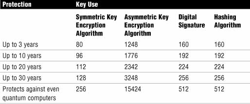
Now that we’ve established that 80 bits or greater is acceptable, let’s speak about the longevity of the keys’ protection. What length of key should be used, grouped by the algorithm that employs it and longevity of protection? Table 6.2 explores those parameters as they relate to longevity of protection. The assumption made in Table 6.2 is that we are protecting against brute force attack. Also, when you look at the table, recall that symmetric algorithms are considered the strongest type of algorithms, thus they necessitate a shorter key length than asymmetric encryption algorithms.
The remainder of this section explores the details of the most common Symmetric Key Encryption algorithms individually.
The following are the main characteristics of DES:
![]() Fixed key length of 64 bits, though only 56 bits are always used for encryption.
Fixed key length of 64 bits, though only 56 bits are always used for encryption.
![]() Hardware acceleration is relatively simple because of its logical (binary) operation.
Hardware acceleration is relatively simple because of its logical (binary) operation.
![]() 40-bit DES is still 56-bits: 40-bit key plus 16 known bits to pad the key out to 56 bits.
40-bit DES is still 56-bits: 40-bit key plus 16 known bits to pad the key out to 56 bits.
![]() Block cipher modes include the following:
Block cipher modes include the following:
![]() ECB (Electronic Code Block) mode.
ECB (Electronic Code Block) mode.
![]() CBC (Cipher Block Chaining) mode. IPsec VPNs mostly choose this.
CBC (Cipher Block Chaining) mode. IPsec VPNs mostly choose this.
![]() Stream cipher modes include the following:
Stream cipher modes include the following:
![]() CFB mode (Cipher Feedback). Similar to CBC.
CFB mode (Cipher Feedback). Similar to CBC.
![]() OFB mode (Output Feedback).
OFB mode (Output Feedback).
Although DES is considered obsolete, mostly because of its small key size, it can be used for small amounts of data where no alternative exists. It is susceptible to brute force attacks on its keys, having been cracked in 2001 in 22 hours.
Here are some other guidelines to make a DES cryptosystem as secure as possible:
![]() Change keys frequently.
Change keys frequently.
![]() Use a secure channel to exchange keys between the sender and receiver. (Diffie-Hellman is one method.)
Use a secure channel to exchange keys between the sender and receiver. (Diffie-Hellman is one method.)
![]() Use CBC if possible. In CBC block cipher mode, encryption of one 64-bit block depends on the previous blocks.
Use CBC if possible. In CBC block cipher mode, encryption of one 64-bit block depends on the previous blocks.
![]() Use 3DES if possible.
Use 3DES if possible.
The following are the main characteristics of 3DES:
![]() Basic algorithm is identical to DES, just applied three successive times.
Basic algorithm is identical to DES, just applied three successive times.
![]() Can use two or three 56-bit keys to achieve 112- or 168-bit key strength. (See the next Exam Alert.)
Can use two or three 56-bit keys to achieve 112- or 168-bit key strength. (See the next Exam Alert.)
![]() 3DES is not significantly more processor-intensive than DES, making it a good choice for software-based encryption.
3DES is not significantly more processor-intensive than DES, making it a good choice for software-based encryption.
![]() 3DES is considered the most trusted of symmetric encryption algorithms by virtue of how long it has been used, as well as its key length.
3DES is considered the most trusted of symmetric encryption algorithms by virtue of how long it has been used, as well as its key length.
Note
Don’t confuse the trustworthiness of an encryption algorithm with its strength. Although AES is considered cryptographically stronger than 3DES, it has only been a NIST standard since 2001 and an official U.S. government standard since May 2002, whereas 3DES has been tested in the field for more than 35 years and has not been found to possess any flaws. Brute force attacks are considered to be unfeasible against 3DES.
If you use DES as a verb, 3DES has sometimes (and rather lazily) been described as producing ciphertext from cleartext that has been DES’d three times. Strictly speaking this is true, but it also implies that the cleartext is encrypted three times. This is incorrect. In fact, Figure 6.5 illustrates how 3DES operates. The numbering in the figure matches the following steps:
-
The cleartext data is first encrypted with a 56-bit key creating ciphertext.
-
This ciphertext is then decrypted (not encrypted!) with a second 56-bit key. Because the second key is always different than the first key, actual decryption doesn’t occur, so effectively the result is also ciphertext.
-
The ciphertext from step 2 is again encrypted, either with a third different key or with the same one that was used in step 1.

Note
If three different keys are used, (K1, K2, and K3 in Figure 6.5), then the total key length is said to be 168 bits. If only two keys are used (that is, K1 and K3 are the same and K2 is different), then the total key length is said to be 112 bits. Cisco does not use 112-bit 3DES in its IPsec VPN implementation.
Surprisingly, if you use the three different keys, and all three steps encrypted in succession from the original cleartext, the composite key strength would be only 58 bits! The encrypt-decrypt-encrypt (EDE) process that 3DES uses is known as 3DES-EDE.
It might take several years before AES is as trusted as 3DES, but it is considered a stronger algorithm. In 1997, NIST announced a competition that was open to the public, inviting them to submit a proposal for an encryption algorithm that would eventually replace DES. Of the fifteen proposed candidates, the Rijndael algorithm was chosen to become AES. Twofish and RC6 were two other candidates. Rijndael is a combination of the names of the inventors, Vincent Rijmen and Joan Daemen.
The following are the main features of AES:
![]() AES uses a variable block length and variable key length. Blocks can be 128, 192, or 256 bits in length and encryption keys can be 128, 192, or 256 bits in length.
AES uses a variable block length and variable key length. Blocks can be 128, 192, or 256 bits in length and encryption keys can be 128, 192, or 256 bits in length.
![]() AES is future-proof because both block and key lengths can be added to in 32-bit increments.
AES is future-proof because both block and key lengths can be added to in 32-bit increments.
![]() AES is much faster than 3DES, making it ideal for software encryption.
AES is much faster than 3DES, making it ideal for software encryption.
![]() AES is specifically designed for efficient implementation in software or hardware on a number of processor platforms.
AES is specifically designed for efficient implementation in software or hardware on a number of processor platforms.
![]() AES is gaining trust in the security community because it has exhibited no known flaws in 10 years of review.
AES is gaining trust in the security community because it has exhibited no known flaws in 10 years of review.
![]() AES is considered to be stronger than 3DES because it is faster and it allows 192- and 256-bit key lengths.
AES is considered to be stronger than 3DES because it is faster and it allows 192- and 256-bit key lengths.
The default encryption algorithm on Cisco platforms remains 3DES, probably because of its maturity relative to AES.
AES is supported on the following Cisco platforms:
![]() Cisco IOS Software Release 12.2(13)T and later
Cisco IOS Software Release 12.2(13)T and later
![]() Cisco PIX Firewall Software Version 6.3 and later
Cisco PIX Firewall Software Version 6.3 and later
![]() Cisco ASA Software Version 7.0 and later
Cisco ASA Software Version 7.0 and later
![]() Cisco VPN 3000 Software Version 3.6 and later
Cisco VPN 3000 Software Version 3.6 and later
The Software Encryption Algorithm (SEAL) was first published in 1994. The current version, 3.0, was published in 1997.
The following are the main features of SEAL:
![]() SEAL is a stream cipher and is considered very fast.
SEAL is a stream cipher and is considered very fast.
![]() SEAL was first supported in IOS with Release 12.3(7)T.
SEAL was first supported in IOS with Release 12.3(7)T.
![]() SEAL uses a 160-bit encryption key.
SEAL uses a 160-bit encryption key.
![]() SEAL is less processor-intensive than equivalent encryption algorithms.
SEAL is less processor-intensive than equivalent encryption algorithms.
Exam Alert
Routers that have hardware-accelerated encryption do not support SEAL. Also, the VPN peers must support IPsec and have the K9 subsystem.
You can use the show version CLI command to confirm whether your version of IOS has the K9 subsystem required to run SEAL:
CiscoISR-A#show version
Cisco IOS Software, C870 Software (C870-ADVIPSERVICESK9-M), Version
12.4(15)T5, RELEASE SOFTWARE (fc4)
Technical Support: http://www.cisco.com/techsupport
Copyright (c) 1986-2008 by Cisco Systems, Inc.
Compiled Thu 01-May-08 02:31 by prod_rel_team
ROM: System Bootstrap, Version 12.3(8r)YI2, RELEASE SOFTWARE
CiscoISR-A uptime is 21 hours, 6 minutes
System returned to ROM by power-on
System restarted at 20:45:39 UTC Mon May 26 2008
System image file is "flash:c870-advipservicesk9-mz.124-15.T5.bin"
These encryption algorithms are called Rivest Ciphers, as they were written by Ron Rivest of RSA fame. They are sometimes also called Ron’s Code. They are popular encryption algorithms because of their relative speed and variable key-length.
The following are the main features of Rivest Ciphers:
![]() RC2. Block cipher that features a variable-length key.
RC2. Block cipher that features a variable-length key.
![]() It was designed as a plug-in replacement for DES.
It was designed as a plug-in replacement for DES.
![]() RC4. Stream cipher that features a variable length key.
RC4. Stream cipher that features a variable length key.
![]() RC4 uses the Vernam cipher, but is not considered a one-time pad (OTP) because it uses a pseudo-random key.
RC4 uses the Vernam cipher, but is not considered a one-time pad (OTP) because it uses a pseudo-random key.
![]() RC4 Runs very quickly in software.
RC4 Runs very quickly in software.
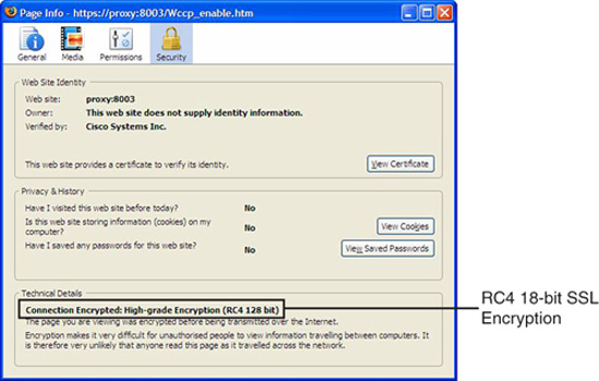
![]() RC4 is often used to secure real-time communications such as e-commerce sites that use SSL or SSL VPNs like Cisco’s SSL VPN solution. (See the example in Figure 6.6.)
RC4 is often used to secure real-time communications such as e-commerce sites that use SSL or SSL VPNs like Cisco’s SSL VPN solution. (See the example in Figure 6.6.)
Wired Equivalent Privacy (WEP) is an example of how RC4 can be implemented poorly.
![]() RC5. Block cipher that features speed and a variable block size and a variable key length.
RC5. Block cipher that features speed and a variable block size and a variable key length.
![]() RC6. Block cipher that lost out to Rijndael in the AES competition. Based on RC5.
RC6. Block cipher that lost out to Rijndael in the AES competition. Based on RC5.
Figure 6.6 illustrates a website certificate for a Cisco Content Engine CE-590 indicating a 128-bit RC4 encrypted SSL link.
Recall from the previous discussion in this chapter that a cryptographic hash is sometimes described as one-way encryption—encryption where there is no possibility of decryption. Hashing algorithms, like encryption algorithms, take cleartext data and, using an encryption key, transform the cleartext data into something different and unreadable by an attacker. But what comes out of the hashing process is not ciphertext as with encryption algorithms, but rather a fixed-length hash or digest. The implication with ciphertext is that it will be deciphered. With a hash, the whole purpose is that it essentially cannot be deciphered as it is extremely infeasible to do so. The two most popular hashing algorithms are Message Digest 5 (MD5) and Secure Hashing Algorithm 1 (SHA-1). These will be discussed separately in their own sections shortly.
Note
The output of the hashing functions is a fixed-length hash or “digest.” Think of a hashing function as a hungry beast into whose mouth you pour in data of variable lengths. The animal digests it and then outputs it (the analogy gets a bit ugly here) into fixed-length digests. The digestion algorithm of the animal can be either of the following:
![]() Message Digest 5 (MD5). Creates 128-bit digests.
Message Digest 5 (MD5). Creates 128-bit digests.
![]() Secure Hashing Algorithm 1 (SHA-1). Creates 160-bit digests.
Secure Hashing Algorithm 1 (SHA-1). Creates 160-bit digests.
In both cases, the output is completely unrecognizable from the input. It is important to realize that the hashing function does not define the formatting of the output, but rather the process to completely disassociate it from the input.
Hashing functions are most commonly used as an integrity check, similar to a frame check sequence (FCS) in a frame. When data is transmitted, a hash of that transmitted data is appended to the data to be checked by the receiver. If the receiver determines that the computed hash is different than the hash appended to the message, the receiver assumes that the data has been tampered with. The key here is the word computed. The receiver computes the hash using the same algorithm that was used with the appended hash.
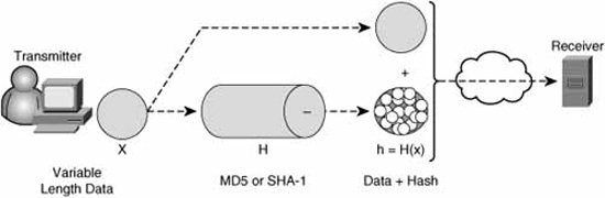
It is common to represent a hashing algorithm as a mathematical function (because that’s what it is!):
h = H(x)
Where:
h = The computed hash.
H = The hashing function (MD5 or SHA-1).
x = The data of variable length fed into the hashing function.
Figure 6.7 represents a simple hashing cryptosystem.
Note
In general, hashing functions should be “collision resistant,” meaning that two messages with the same hash are very unlikely.
If that was all there was to it, an attacker could launch a man-in-the-middle attack that would go something like this:
-
Seize the data with the original hash.
-
Alter it.
-
Compute and append a new hash by making an educated guess as to which of the two popular hashing algorithms (MD5 or SHA-1) was used.
-
Transmit the altered data with the new hash to the receiver.
So, how good is the hash as an integrity check if we left it right there? Not very good, right? The reason standalone hashing functions were designed this way was to serve as a lightweight, simple, but effective way to guarantee the integrity of transmission over telecommunication circuits of sometimes dubious quality. If a receiving station finds that a message fails the integrity check, it can ask for a retransmission from the transmitting station. The assumption is that the communication links between the transmitter and receiver are not hostile, which would be true in the case of closed networks such as leased-line, circuit-switched, or packet-switched networks.
If, however, the intermediate network is the Internet or some other network that is considered hostile by our security policy, we should find a way to assure the authenticity of the hash itself. The transmitter would create a hash made of the following:
![]() A shared-secret encryption key.
A shared-secret encryption key.
![]() + the variable-length data.
+ the variable-length data.
Thus, only if the receiver possesses the same shared-secret encryption key would it be able to compute the same hash with the same variable-length data. This is how Hashing Message Authentication Codes (HMACs) work. HMACs are hashing functions with the addition of a shared-secret encryption key. This makes for a hashing cryptosystem that is much more resistant to a man-in-the-middle attack.
Figure 6.8 illustrates the addition of a shared-secret encryption key to create an HMAC instead of a simple hash before the data is transmitted.

Cisco uses two popular HMACs:
![]() Keyed MD5
Keyed MD5
![]() Keyed SHA-1
Keyed SHA-1
They are based respectively on MD5 and SHA-1 hashing functions.
Note
If you’re keeping track, we have now achieved the I and A in C-I-A. IPsec VPNs use HMAC functions to assure data integrity and to provide origin authentication. Only the holder of the same shared-secret key could create a hash that can be matched by the receiver.
The following are the main features of the MD5 hashing algorithm:
![]() MD5 is very common (ubiquitous).
MD5 is very common (ubiquitous).
![]() MD5 was derived from its predecessor, MD4.
MD5 was derived from its predecessor, MD4.
![]() MD5 uses a complex sequence of logical (binary) operations that result in a 128-bit message digest.
MD5 uses a complex sequence of logical (binary) operations that result in a 128-bit message digest.
![]() MD5 is not recommended for new cryptosystems because SHA-1 is preferred for its theoretically higher security.
MD5 is not recommended for new cryptosystems because SHA-1 is preferred for its theoretically higher security.
![]() MD5 was invented by Ron Rivest.
MD5 was invented by Ron Rivest.
MD5 is less trusted than SHA-1 because of some theoretical weaknesses in some of its building blocks. This kind of speculation makes the cryptology world somewhat uneasy. Thus, although it has not been proven in the real world that MD5 is any less safe than SHA-1, SHA-1 is preferred over MD5 because any risk should be avoided.
Theoretically, SHA-1 should be marginally slower than MD5 on the same platform because it works with a 32-bit longer buffer than MD5, but it should be more resistant to a brute force attack for that very reason.
The following are the main features of the SHA-1 hashing algorithm:
![]() Similar to MD4 and MD5 in that it takes an input message, x, of no more than 264 bits.
Similar to MD4 and MD5 in that it takes an input message, x, of no more than 264 bits.
![]() Produces a 160-bit message digest.
Produces a 160-bit message digest.
![]() Slightly slower than MD5.
Slightly slower than MD5.
![]() SHA-1 corrects an unpublished flaw in its predecessor, SHA.
SHA-1 corrects an unpublished flaw in its predecessor, SHA.
![]() SHA-1 is published as an official NIST standard as FIPS 180-1.
SHA-1 is published as an official NIST standard as FIPS 180-1.
Another way of securing messages among devices and people in a cryptosystem is the use of a digital signature. Digital signatures are usually derived from digital certificates, which are part of a Public Key Infrastructure (PKI). As their name suggests, when digital signatures are used instead of hashes and HMACs in transactions, the sender cannot disavow themselves from the transaction. This is called non-repudiation, and simply means that the data came uniquely (and could only have originated) from the holder of the digital signature.
Here are the most common uses for digital signatures:
![]() Non-repudiation
Non-repudiation
![]() Authenticating users
Authenticating users
![]() Proving both the authenticity and integrity of PKI-generated certificates
Proving both the authenticity and integrity of PKI-generated certificates
![]() Signed timestamps
Signed timestamps
In Figure 6.9, a user is composing an email message to Bob’s email address, [email protected], telling him to take the day off. The user clicks the button (1) in the email message, indicating that it should be digitally signed and when (2) the message is sent, a message (3) pops up, indicating that the message is about to be signed by the user’s private key.
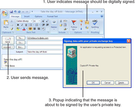
The question is whether the email message really came from Bob’s boss. Clearly, Bob should only take the day off if the message actually originated from his boss and Bob can verify the message upon receipt. If he verifies the message successfully, then only the boss or someone with access to the boss’s computer (and private key) could have sent it. The message source is non-reputable.
Figure 6.10 shows the process of sending a digitally signed email message.

Here’s how it works. The assumption is that Bob and Bob’s boss have agreed upon a signature algorithm:
-
Bob’s boss signs the email message with her private signature key. This key must be kept secret.
-
A digital signature is generated by the signature algorithm using Bob’s boss’s signature key.
-
The boss’s email application attaches the digital signature to the email message and sends it to Bob.
-
Bob’s email application verifies the signature using the (typically publicly available) verification key.
-
If the message verifies successfully, then it can only have originated from Bob’s boss’s computer (non-repudiation) because only the holder of the private key can produce a digital signature that can be verified with the corresponding public key. Furthermore, the verification check confirms that the data has not changed in transit, thus assuring its integrity.
Note
Technically, the sender’s private signature key and the receiver’s public verification keys can be any agreed-upon keys, but the use of Public Key Infrastructure (PKI) is recommended to manage the keys; this will ensure their safeguarding and improve the scalability of the solution.
The whole process hinges on the digital signature algorithm used, so it only makes sense that there should be a Digital Signature Standard. DSS was first issued in 1994 by NIST. Originally, there was only one standard, but now DSS incorporates three, as follows:
![]() Digital Signature Algorithm (DSA):
Digital Signature Algorithm (DSA):
![]() The original standard.
The original standard.
![]() Not as flexible as RSA.
Not as flexible as RSA.
![]() Slow verification of signatures.
Slow verification of signatures.
![]() Digital Signature Using Reversible Public Key Cryptography (RSA). An RSA digital signature algorithm. This is commonly referred to as simply “RSA,” although this is technically incorrect.
Digital Signature Using Reversible Public Key Cryptography (RSA). An RSA digital signature algorithm. This is commonly referred to as simply “RSA,” although this is technically incorrect.
![]() Elliptic Curves Digital Signature Algorithm (ECDSA). Also added to the DSS.
Elliptic Curves Digital Signature Algorithm (ECDSA). Also added to the DSS.
One of the main issues with symmetric key cryptosystems is that they don’t scale very well. Asymmetric key cryptosystems, where different keys are used for encrypting and decrypting, scale well. This is mainly because the management of these asymmetric keys is integral to the same infrastructure that is used to generate and issue them in the first place. In this section, we examine the principles behind asymmetric key encryption and look at popular encryption algorithms that use asymmetric keys including Rivest Shamir Adleman (RSA), Diffie-Hellman (DH), and public key infrastructure (PKI).
Asymmetric algorithms are slower than symmetric algorithms because they are more mathematically complex. Because they are slower, they are not typically used in real-time encrypted data flows and are instead used as key exchange protocols. Symmetric algorithms are discussed in the section, “Exploring Symmetric Key Encryption.”
Asymmetric encryption algorithms provide for both confidentiality and authentication. They are often called public key algorithms. They are asymmetric in that each party to the cryptosystem has two keys, contained in a “key pair” consisting of a private key and a corresponding public key:
![]() Private key. This key is not freely distributed, and is closely guarded, thus ensuring confidentiality.
Private key. This key is not freely distributed, and is closely guarded, thus ensuring confidentiality.
![]() Public key. Usually freely available, and distributed to any entity that wants to enter into confidential communication with the system that holds the corresponding private key.
Public key. Usually freely available, and distributed to any entity that wants to enter into confidential communication with the system that holds the corresponding private key.
Both keys are capable of encrypting data. If the private key is used for encrypting data, the corresponding public key is used to decrypt the data and vice versa.
Examples of public key encryption algorithms include the following:
![]() RSA:
RSA:
![]() Invented in 1997 by Rivest, Shamir, and Adleman.
Invented in 1997 by Rivest, Shamir, and Adleman.
![]() Often used in digital signatures for authentication and non-repudiation.
Often used in digital signatures for authentication and non-repudiation.
![]() 100 times slower than DES in hardware and 1,000 times slower than DES in software.
100 times slower than DES in hardware and 1,000 times slower than DES in software.
![]() Consequently, it can be used for encryption but not typically for large quantities of data.
Consequently, it can be used for encryption but not typically for large quantities of data.
![]() DSA. Digital Signature Algorithm (part of DSS).
DSA. Digital Signature Algorithm (part of DSS).
![]() DH. Diffie-Hellman key exchange algorithm. Describes a method for generating a shared secret encryption key in a secure fashion over an unsecure network. The DH key exchange uses the peers’ public and private key pairs as part of its algorithm. Very commonly used by Internet Key Exchange (IKE) Phase I during the establishment of an IPsec VPN session. See the next chapter for more information.
DH. Diffie-Hellman key exchange algorithm. Describes a method for generating a shared secret encryption key in a secure fashion over an unsecure network. The DH key exchange uses the peers’ public and private key pairs as part of its algorithm. Very commonly used by Internet Key Exchange (IKE) Phase I during the establishment of an IPsec VPN session. See the next chapter for more information.
![]() ElGamal. An asymmetric key encryption algorithm based on the DH key agreement. First described by Taher Elgamal in 1984.
ElGamal. An asymmetric key encryption algorithm based on the DH key agreement. First described by Taher Elgamal in 1984.
![]() Elliptic Curve. Used for both encryption and also part of DSS.
Elliptic Curve. Used for both encryption and also part of DSS.
In order to encrypt a message to an entity (a box or a person), you need their public key. The transmitter encrypts the message with an agreed-upon encryption algorithm and the receiver’s public key. The receiver decrypts the message with the receiver’s private key. Confidentiality is assured because only the holder of the private key can decrypt the message. Thus:
Encrypt (public key) + Decrypt (private key) = confidentiality
We discussed digital signatures in the last section. This is an example of how authentication works with asymmetric keys. Remember how Bob’s boss signed the email message with her private key, and Bob verified the email message with the boss’s public key? Authentication is assured because only Bob’s boss could have encrypted a message that is verified with the boss’s public key. Thus:
Encrypt (private key) + Decrypt (public key) = authentication
In large-scale asymmetric encryption cryptosystems, Public Key Infrastructure (PKI) is often used to manage the keys. The integrity of the cryptosystem itself revolves around the trust inherent in the PKI employed. Because the cryptosystem’s private keys are managed by the framework of the PKI, a badly managed PKI would lead to an untrustworthy cryptosystem. All the devices, users, and other entities within the cryptosystem leverage on this trust. If their credentials (certificates, keys, and so on) can be proved to be issued by the same, trusted third-party authority, then the entities will trust one another.
Thus, in a PKI, it is all about trust. Here is some terminology providing a framework for a discussion of PKI:
![]() PKI. A trust framework that supports technologies in a Public Key technology implementation.
PKI. A trust framework that supports technologies in a Public Key technology implementation.
![]() Certificate Authority (CA). The trusted third party that signs public keys.
Certificate Authority (CA). The trusted third party that signs public keys.
![]() Certificates. Documents that associate names to the public keys that have been signed by the CA.
Certificates. Documents that associate names to the public keys that have been signed by the CA.
Note
User’s certificates are always signed by a CA; otherwise, they lack validity and are not trustworthy. CAs have certificates themselves that contain their public key. Who does the CA trust? Itself, of course! These so-called CA certificates are self-signed by the CA because hierarchically the CA is at the top of the trust “org chart.”
PKIs don’t just happen. Neither are they just users and certificates. PKIs comprise five main areas, as follows:
![]() CAs. Address key management and issuance.
CAs. Address key management and issuance.
![]() PKI Users. Some examples are VPN gateways, routers, people, and e-commerce servers
PKI Users. Some examples are VPN gateways, routers, people, and e-commerce servers
![]() Storage and Protocols:
Storage and Protocols:
![]() How are credentials (keys, certificates) safely stored and distributed?
How are credentials (keys, certificates) safely stored and distributed?
![]() Some of the enrollment and issuance procedures can be automated.
Some of the enrollment and issuance procedures can be automated.
![]() Supporting Organizational Framework. Practices and procedures and user authentication using Local Registration Authorities (LRAs), integrated into the organization’s comprehensive security policy.
Supporting Organizational Framework. Practices and procedures and user authentication using Local Registration Authorities (LRAs), integrated into the organization’s comprehensive security policy.
![]() Supporting Legal Framework. Acceptable Use Policy (AUP), incident response, policies for lost or stolen keys, and so on.
Supporting Legal Framework. Acceptable Use Policy (AUP), incident response, policies for lost or stolen keys, and so on.
There are two basic PKI topologies, central (single-root) and hierarchical. These are illustrated in Figures 6.11.

This is the simplest way to implement a PKI. Certificates are issued by one CA. Its most obvious advantage is its simplicity, but having one root CA has some disadvantages:
![]() Not scalable to large environments; for example, across several departments within a federal government.
Not scalable to large environments; for example, across several departments within a federal government.
![]() Topology requires one centralized administration where all the trust decisions are made.
Topology requires one centralized administration where all the trust decisions are made.
![]() Single point of failure. If the single root CA is compromised, then the whole PKI is, because all the public keys have been signed by the same CA.
Single point of failure. If the single root CA is compromised, then the whole PKI is, because all the public keys have been signed by the same CA.
A hierarchical CA delegates the root CA’s authority to subordinate CAs, thereby distributing trust. A compromise of a subordinate CA’s private key only compromises the public keys that it has signed. Ultimately, all subordinate CAs’ public keys have been signed by the same root CA; no matter the depth of the hierarchy, there is only one root. Thus, users trust certificates issued to other users within the same hierarchy. In Figure 6.11, even though Alice and Bob are in different departments of the same company, their CA’s certificates were issued by the same root CA, and thus Alice trusts Bob.
This chain of logic is called the certification path.
Some Public Key Infrastructures are designed such that users are required to possess two key pairs: one for encryption and another one for signing. These key pairs can be different strengths. This necessitates two certificates for the user: one for encryption and another for signing. (Recalling that the certificate contains the user’s public key.)
Many organizations require that the CA be kept under lock and key and, in some cases, powered down until it is needed to sign certificates. This is because the security of the CA defines the security and trustworthiness of the whole PKI. Depending on the scale of the solution, some of the day-to-day management tasks in a PKI can be offloaded (delegated) to a Registration Authority (RA), minimizing the CA’s exposure. Some of these tasks may include the following:
![]() User authentication during enrollment.
User authentication during enrollment.
![]() User key generation. (If required, normally the client will create its own public key, which is signed by the CA when the enrollment request is approved and the certificate issues.)
User key generation. (If required, normally the client will create its own public key, which is signed by the CA when the enrollment request is approved and the certificate issues.)
![]() Certificate distribution.
Certificate distribution.
Note
In general, PKI is a good fit for an IPsec VPN because if a VPN peer is compromised and its certificate quickly revoked by a PKI administrator, that peer can no longer use that certificate to connect to the VPN. This is very effective if the VPN peers check the Certificate Revocation List (CRL), which is issued by the CA, whenever authentication occurs.
Standardization of PKI protocols is crucial, especially when interoperability of PKI protocols is required. One example of this that we’ve already seen is in cross-certification of CAs. PKI also should work with other standards, such as the following:
![]() X.500 directory services
X.500 directory services
![]() Public Key Cryptography Standards (PKCS)
Public Key Cryptography Standards (PKCS)
![]() Lightweight Directory Access Protocol (LDAP)
Lightweight Directory Access Protocol (LDAP)
Some of these standards define user information databases and information repositories. It is very convenient (especially when these other services already exist) that PKI interoperates with them.
The most common standard for the PKI framework is X.509 v3. X.509 defines the certificate structure. Its use is widespread in the following:
![]() Servers. Web, email, LDAP, and other servers using SSL and TLS.
Servers. Web, email, LDAP, and other servers using SSL and TLS.
![]() Web Browsers. SSL and TLS.
Web Browsers. SSL and TLS.
![]() Email Programs. Secure Multipart Internet Mail Extension (S/MIME) attachments.
Email Programs. Secure Multipart Internet Mail Extension (S/MIME) attachments.
![]() IPsec VPNs. Used for authentication instead of simple pre-shared keys (PSKs) during the IKE Phase I negotiation. (See Chapter 7.)
IPsec VPNs. Used for authentication instead of simple pre-shared keys (PSKs) during the IKE Phase I negotiation. (See Chapter 7.)
PKCS defines the formatting of data that is exchanged between the different elements within a PKI. It was developed to promote interoperability, as well as standardize PKI APIs. Some important examples of these standards include the following:
![]() PKCS #1: RSA Cryptography.
PKCS #1: RSA Cryptography.
![]() PKCS #2: DH Key Agreement.
PKCS #2: DH Key Agreement.
![]() PKCS #7: Cryptographic Message Syntax (see note below).
PKCS #7: Cryptographic Message Syntax (see note below).
![]() PKCS #10: Certificate Request Syntax (see note below).
PKCS #10: Certificate Request Syntax (see note below).
Note
Think of PKCS #7 and #10 as standards for encapsulation of information between elements in a PKI. In this way, it is similar to network protocols because these standards define rules for communicating information between PKI peers. For example, a certificate enrollment request may be contained in a PKCS #10 envelope and transmitted in turn as the payload of PKCS #7 message to the CA. The issued X.509 v3 certificate is encapsulated as the payload of a PKCS #7 message.
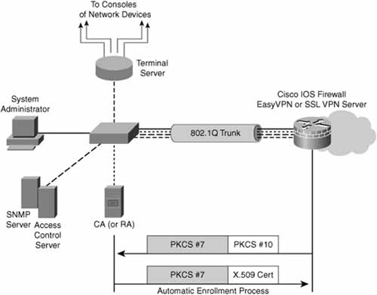
SCEP automates the procedure of enrolling in a CA and the issuing of certificates. It is most commonly used in IPsec VPNs where the VPN peers use certificate-based authentication and where manual enrollment is not practical. SCEP not only automates the secure issuance of certificates, but it manages the whole PKI life cycle, including automatic renewal of certificates that are close to their expiry date.
Figure 6.12 shows a simple depiction of this process using the reference network design introduced with Figure 4.1 in Chapter 4, “Implementing Secure Management and Hardening the Router.”
There are three basic steps involved in enrolling in a CA. Naturally, the first step is making sure that the participants in the PKI trust the CA. This is done by retrieving and validating the CA’s certificate. At a high-level, the three steps are as follows:
-
Retrieving the CA Certificates. The PKI participants retrieve the CA’s certificate and validate (authenticate) it. Cisco recommends using some out-of-band (relative to the network) channel for the most secure solution. For example, validation of the CA certificate may be as simple as faxing the information found in the CA’s X.509 certificate and the CA’s public key to the CA administrator and asking that they validate it by return fax.
-
Certificate Enrollment. Assuming that the CA’s certificate is validated successfully, the PKI participants now trust the CA to issue identity certificates. The PKI participants enroll in the CA by sending a certificate request to the CA. This request contains the user’s self-generated public key; the user’s corresponding private key is retained on the user’s device. (The PKI can also be configured so the CA generates the private and public key pair.) The CA issues the certificate after validating the user’s enrollment request. Like the validation of the CA’s certificate on the part of the user, Cisco recommends that the user’s certificate request is validated using an out-of-band method by the CA. (Only seems fair!)
Note
Note the terminology in step 2. The participants enroll in the Certificate Authority. This process can be automated (SCEP) or it can be a manual process. When SCEP is used, steps 1 through 3 are all automated, though the CA administrator will likely reserve the right to manually issue the pending enrollment requests before they can be retrieved.
The participants in a PKI can be people or machines.
-
Certificate Issuance/Retrieval. The certificate is issued by the CA. As noted, this process is typically manual for security reasons. The PKI participants can now retrieve the issued certificates from the CA. This might involve visiting a special web page on the CA or some other method, such as an attachment to an email message from the CA administrator.
When steps 1 through 3 are complete, each participant in the PKI will possess the following:
![]() The CA’s certificate.
The CA’s certificate.
![]() Participant’s identity certificate (containing the participant’s signed public key) signed by the CA.
Participant’s identity certificate (containing the participant’s signed public key) signed by the CA.
![]() A key pair:
A key pair:
![]() Participant’s public key.
Participant’s public key.
![]() Participant’s corresponding private key.
Participant’s corresponding private key.
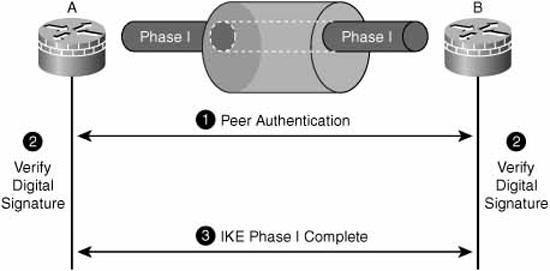
Now that the participants have the CA’s certificate, their own identity certificate and a key pair, they can authenticate to one another without the involvement of the CA. Because they possess identity certificates that have been signed by the same CA, they should naturally trust one another. The PKI participants could be IPsec VPN peers, as in Figure 6.13.
Note
If you have skipped to this part of the chapter and are not familiar with the concept of digital signatures, you owe it to yourself to go to the section “Digital Signatures” in this chapter before reviewing the following steps. Recall that the digital signature is derived from the certificate.
The actual mechanics of certificate-based authentication are as follows:
-
The PKI participants exchange certificates.
-
The participants verify each other’s digital signatures. This step consists of each participant:
a. Hashing the plaintext portion of the other participant’s certificate.
b. Decrypting the other participant’s digital signature using the CA’s public key (contained in the CA’s certificate).
c. Comparing the results in steps a and b. If they match, the participant’s certificate has been issued by the same CA.
-
Internet Key Exchange (IKE) Phase I completes. (The mechanics of what happens inside IKE Phase I beyond this authentication process will be examined in Chapter 7.)
We’ve mentioned IPsec, SSL VPN servers and application layer servers (such as email and web servers) as common applications of certificates. One CA server can issue certificates that can be used for all these types of authentication, as long as the participants in the PKI support the same procedures for enrollment, issuance, and installation.
Certificates are often seen at the application layer of the OSI model in the following ways:
![]() SSL
SSL
![]() TLS
TLS
![]() S/MIME (Secure Multi-part Internet Mail Extension)
S/MIME (Secure Multi-part Internet Mail Extension)
![]() PGP (Pretty Good Privacy)
PGP (Pretty Good Privacy)
The most common Cisco uses of certificates include:
![]() IPsec—certificate-based authentication during IKE Phase I
IPsec—certificate-based authentication during IKE Phase I
![]() 802.1X using EAP-TLS (Extensible Authentication Protocol-TLS)
802.1X using EAP-TLS (Extensible Authentication Protocol-TLS)
![]() TN3270 over SSL (IBM Telnet protocol using SSL encryption)
TN3270 over SSL (IBM Telnet protocol using SSL encryption)
![]() SSL VPN Servers (WebVPN solution; see Chapter 7)
SSL VPN Servers (WebVPN solution; see Chapter 7)