
Secure management and reporting is too often applied on top of a secure architecture as an afterthought rather than being designed into the solution from the beginning. Some hard questions need to be asked early on in the design because they bear on the implemented secure architecture. These questions are typically asked during the Initiation phase and answered during the Acquisition and Development phase of the Cisco Secure Network Life Cycle first introduced in Chapter 2, “Building a Secure Network Using Security Controls.” In general, what types of activity need to be logged and what protocols and devices are required to perform these functions will determine the technology deployed during the Implementation phase of the Cisco Secure Network Life Cycle.
Exam Alert
The context of this discussion, as well as others throughout this book, is determined by the Cisco Secure Network Life Cycle. The steps of the lifecycle are listed next with the secure management and reporting topics to be discussed (in parentheses beside it):
Initiation (What to log? How to log?).
Acquisition and Development (Guidelines for secure management and reporting).
Implementation (Cisco solutions for secure management and reporting).
Operations and Maintenance.
Disposition.
Use the Cisco Secure Network Life Cycle as a framework for memorizing this information for the exam. For example, syslog as a management protocol is presented as a possible answer to the question, “How to log?” (Initiation). Recommendations are then made as to how to use syslog (Acquisition and Development), followed by outlining Cisco products that use syslog as a centerpiece for secure management and reporting (Implementation).
Planning for secure management and reporting is based on guidelines set out by the comprehensive security policy. Several questions need to be answered before secure management and reporting can be integrated into the network security architecture design and then configured. The questions that need to be answered can be grouped into two broad categories, as follows:
![]() “What to log (or report)?” questions.
“What to log (or report)?” questions.
![]() “How to log (or report)?” questions.
“How to log (or report)?” questions.
Let’s break this down a bit further.
Issues that bear heavily on the first question would be whether the data collected might be used for forensic purposes in investigating a possible network compromise or possibly for criminal prosecution. Rules of evidence, chain of custody, timestamps on log entries, and so on would need to be laid out. The answers to these questions will lead to administrative controls. Some helpful questions include the following:
![]() What are the most critical events to log?
What are the most critical events to log?
![]() What are the most important logs?
What are the most important logs?
![]() What log data may be required for forensic investigation and prosecution?
What log data may be required for forensic investigation and prosecution?
The answers to these questions are specific to the organization and thus vary. For example, an organization that is planning to prosecute a possible network compromise in criminal court would be well advised to log all successful and unsuccessful network login attempts, as well as users’ activity once logged on and place timestamps on the events logged with a common clock synchronized from a recognized time source. On the other hand, an Internet Service Provider (ISP) that simply needs to keep track of login activities for billing purposes might simply need logs that reflect accurate network login and logoff by users.
After the administrative controls have been put in place that set out what needs to be logged, then the mostly technical controls that define how the events will be logged can be laid out.
We saw in Chapter 2, “Building a Secure Network Using Security Controls,” that Cisco has a number of solutions as part of the Cisco Integrated Security Portfolio. These solutions include security management products for multiple devices like Cisco Security MARS, with integral logging and report generation facilities for large networks. Here are some useful questions to ask when deciding on the technical controls needed to report and log events in the network:
![]() How can the integrity of both the logs, as well as the communication channels in which the log messages flow, be assured?
How can the integrity of both the logs, as well as the communication channels in which the log messages flow, be assured?
![]() How can the confidentiality of both the logs, as well as the communication channels in which the log messages flow, be assured?
How can the confidentiality of both the logs, as well as the communication channels in which the log messages flow, be assured?
![]() How do you deal with the copious amounts of log messages?
How do you deal with the copious amounts of log messages?
![]() How do you ensure that logs all use timestamps from the same clock to properly correlate events with logs, as well as logs with other logs?
How do you ensure that logs all use timestamps from the same clock to properly correlate events with logs, as well as logs with other logs?
![]() How can messages be prioritized so that critical messages are separated from routine messages?
How can messages be prioritized so that critical messages are separated from routine messages?
![]() How can changes be reported when network outages or attacks occur?
How can changes be reported when network outages or attacks occur?
![]() How do you log events from several devices in one central place?
How do you log events from several devices in one central place?
These questions will be answered in the subsequent sections using the Cisco Secure Life Cycle as a guideline.
So many questions! Nevertheless, these types of questions must be answered before the acquisition and integration of technology is considered. We will not try to answer these questions now, so we will take a shortcut and assume that they have been adequately answered in the reference architecture that we will be using for the subsequent sections in this chapter.
Figure 4.1 represents a typical architecture for secure management and reporting. It leverages on technologies that the reader would have examined in their CCNA studies, particularly in its use of VLANs to separate the traffic inside the network perimeter into different planes. It will serve as a simple visual tool to provide context for several of the Implementation phase guidelines that will be recommended presently.

The following is a quick explanation of the reference architecture in Figure 4.1. A Cisco IOS firewall with VPN is protecting an organization’s network.
The firewall has three interfaces on it. The interfaces are connected to the following:
![]() The Internet
The Internet
![]() An inside production network
An inside production network
![]() An IEEE 802.1Q trunk to a Cisco Catalyst layer 2 Ethernet switch
An IEEE 802.1Q trunk to a Cisco Catalyst layer 2 Ethernet switch
Here is an explanation of some of the other security features found in the reference architecture:
![]() Ports on the Cisco Catalyst switch are configured in several VLANs (four pictured).
Ports on the Cisco Catalyst switch are configured in several VLANs (four pictured).
![]() The Cisco IOS firewall is routing among these VLANs (router-on-a-stick).
The Cisco IOS firewall is routing among these VLANs (router-on-a-stick).
![]() ACLs on the Cisco IOS firewall manage traffic between the different VLANs. (See Chapter 5, “Using Cisco IOS Firewalls to Implement a Network Security Policy.”)
ACLs on the Cisco IOS firewall manage traffic between the different VLANs. (See Chapter 5, “Using Cisco IOS Firewalls to Implement a Network Security Policy.”)
![]() The firewall is stateful (see Chapter 5) and supports a remote access IPsec VPN for management (see Chapter 7, “Virtual Private Networks with IPsec”).
The firewall is stateful (see Chapter 5) and supports a remote access IPsec VPN for management (see Chapter 7, “Virtual Private Networks with IPsec”).
![]() Deployed in different VLANs are the following:
Deployed in different VLANs are the following:
![]() Cisco Security MARS Appliance
Cisco Security MARS Appliance
![]() SNMP Server
SNMP Server
![]() Cisco Secure Access Control Server (ACS)
Cisco Secure Access Control Server (ACS)
![]() System Administrator PC
System Administrator PC
![]() Terminal Server (Used to connect to the console ports of all the network devices.)
Terminal Server (Used to connect to the console ports of all the network devices.)
![]() Production Network
Production Network
Note
This is a simplified secure network design for the sake of the discussion of the secure management and reporting topics throughout this chapter. It will serve the purpose of demonstrating secure management and reporting but it is lacking depth-of-defense for one thing and intrusion prevention/detection for another. IPS and IDS are discussed in Chapter 8, “Network Security Using Cisco IOS IPS.”
Exam Alert
The communication between management hosts and the devices they manage can take two different paths, either by accident or design:
![]() Out-of-band (OOB). The traffic flows within a network separate from the production network. It is not in the data plane.
Out-of-band (OOB). The traffic flows within a network separate from the production network. It is not in the data plane.
Example: A management VLAN.
![]() In-band. The traffic flows across the production network, the Internet (or other hostile network), or both. It is in the data plane.
In-band. The traffic flows across the production network, the Internet (or other hostile network), or both. It is in the data plane.
Solution: Protect it inside a VPN, either site-to-site or remote access.
Recall the five steps of the Cisco Secure Network Life Cycle. Clearly, we had some productive meetings and answered the “how to log” and “what to log” questions during the Initiation and Acquisition and Development phases. Here are some of the guidelines that will be followed in the Implementation phase of Cisco’s Secure Network Life Cycle:
![]() General Management Guidelines:
General Management Guidelines:
![]() Synchronize clocks on hosts and network devices.
Synchronize clocks on hosts and network devices.
![]() Document changes and make backups of configurations.
Document changes and make backups of configurations.
![]() OOB Management Guidelines:
OOB Management Guidelines:
![]() Find solutions that mitigate the risk of transmitting unsecure management protocols over production networks.
Find solutions that mitigate the risk of transmitting unsecure management protocols over production networks.
![]() In-Band Management Guidelines:
In-Band Management Guidelines:
![]() Only manage devices that require monitoring or managing
Only manage devices that require monitoring or managing
![]() Use encryption (IPsec, SSL, SSH) whenever possible.
Use encryption (IPsec, SSL, SSH) whenever possible.
![]() Determine if management channel has to be open at all times.
Determine if management channel has to be open at all times.
The remaining material in this section addresses these guidelines in detail.
Referring to Figure 4.1, you could deploy a syslog server in one of the private VLANs on the inside of the network. The syslog server would accept messages from any device that is configured as a syslog client—the Cisco IOS firewall, for example. Other network devices and other IP hosts like a public web server or a mail server could be set up to be syslog clients. There are several advantages to having a central syslog server logging events from a number of different sources. As previously discussed, care has to be taken to ensure that the integrity of the log files is assured, and that the communication path between the syslog server and its clients is not compromised. This is where OOB management and in-band management decisions are made. Also, best practices dictate that the devices’ clocks should be synchronized to a recognized time source using the Network Time Protocol (NTP).
Note
If the syslog server is accepting messages from several clients, it is crucial that all the devices’ clocks are synchronized from the same source. For example, if an IPS detects an attempted privilege escalation attack on a web server and sends a message to the log server, it might be necessary to correlate this event with the login logs on the web server itself. If the timestamps on the logs cannot be correlated because the devices’ clocks are not synchronized, it might be difficult to prove that the two events are linked.
Device synchronization is covered in the section, “Configuring Time Features,” later in this chapter.
Logging to a central syslog server is not only part of the solution but potentially also part of the problem. The biggest issue is the enormity of the task of sifting through the resulting information, correlating the events from several different network devices and application servers and taking different types of actions based on a vulnerability assessment of the incident.
This is what Cisco Security MARS can do. Because Cisco Security MARS understands the complete network topology, MARS can intelligently analyze security events and help focus security staff’s efforts in solving the potential problems. For example, false positives are more accurately detected. For example, MARS is used as a reporting and event correlation tool in Chapter 8, “Network Security Using Cisco IOS IPS.” MARS sees the entire security architecture and thus sees security events in their complete context. It is a very complex and useful tool for reporting on security events. MARS is introduced in Chapter 2, “Building a Secure Network Using Security Controls.”
Syslog is a key security policy component, but routers should also be configured to send log messages to one or more of these items:
![]() Console. Physical terminal lines.
Console. Physical terminal lines.
![]() Vtys. Virtual terminal lines.
Vtys. Virtual terminal lines.
![]() Buffered Logging. Internal router circular buffer.
Buffered Logging. Internal router circular buffer.
![]() SNMP Traps. Event-triggered messages to SNMP server.
SNMP Traps. Event-triggered messages to SNMP server.
![]() Syslog. External syslog server.
Syslog. External syslog server.
Not all messages are as important as others. Some messages are simple system level warnings, whereas others may denote real system emergencies that require immediate human intervention as the system is unusable. For example, an attacker may craft an attack that creates a DoS on a router system, resulting in emergency log messages. If no one’s listening, no one knows!
Table 4.1 lists and explains the log severity levels. The “Log String” denotes how the log level appears in a log message.

Note
When you specify a level of syslog messages that you want to log, all levels below that level will be logged as well. For example, if the logging level specified is 4 (Warnings), levels 0–3 will also be sent.
Exam Alert
Memorize Table 4.1. Memorization tip: The lower the level number, the more severe the event.
See Figure 4.2 for the log message format. The example is a level 4 syslog message from an IOS IPS, indicating that a user is attempting to communicate using the MSN Messenger instant messenger (IM) application. The organization’s security policy might forbid the use of IM from its workstations, in which case this potential breach may constitute useful evidence for disciplinary purposes.

Cisco Security Device Manager (SDM) is introduced and examined in Chapter 3, “Security at the Network Perimeter.” Figure 4.3 illustrates how to navigate to the screen to configure syslog on the router.

Starting at the Cisco SDM homepage, follow these steps to enable and configure syslog logging on the Cisco IOS router:
-
Choose Configure->Additional Tasks->Router Properties->Logging.
-
Click Edit in the logging pane.
-
Check the Enable Logging Level check box in the Logging Window and choose the logging level desired from the Logging Level list box.
-
Click Add. In the resulting IP Address/Hostname field, enter the IP address of a logging host (syslog server).
-
Click OK and then OK again to return to the Logging pane.
Note
The CLI commands that result are as follows:
logging buffered 4096
logging trap debugging
logging host 192.168.99.130
logging on
You can use Cisco SDM to monitor the internal buffer log, as well as messages that have been sent to syslog servers by choosing Monitor->Logging and selecting the Syslog tab in the Logging window.
The Simple Network Management Protocol (SNMP) has long been deployed in networks to provide for central management of many types of network devices. There are, however, some notable security flaws in the original implementations of this very important protocol, SNMP version 1 and version 2. The protocol remains a valuable tool, and there will likely be a business case for its use. The vulnerabilities of the protocol will be outlined and discussed, as well as strategies for mitigating them, including the use of (the much newer) SNMP version 3.
The Simple Network Management Protocol (SNMP) enables an administrator to configure, manage, and view information on devices and IP hosts. One advantage of SNMP is that it is vendor-neutral, meaning that a common SNMP architecture can be used for many vendors’ products. There are three main elements to the SNMP architecture:
![]() Manager. Network Management System (NMS). Can retrieve (get) information from agents or change (set) information in the MIB on agents.
Manager. Network Management System (NMS). Can retrieve (get) information from agents or change (set) information in the MIB on agents.
![]() Agent. Managed Node. Agents can send traps when system events occur and respond to sets (configuration commands) and gets (information queries).
Agent. Managed Node. Agents can send traps when system events occur and respond to sets (configuration commands) and gets (information queries).
![]() MIB. Management Information Base. This is the database of information contained on the agent.
MIB. Management Information Base. This is the database of information contained on the agent.
Referring to Figure 4.1, the Cisco Catalyst switch and Cisco IOS firewall could be SNMP agents. The NMS is configured OOB in its own VLAN on an inside network protected by the stateful Cisco IOS firewall.
One of the vulnerabilities of SNMP v1 and v2 architecture is that messages are authenticated using cleartext community strings. Community strings have the following attributes:
![]() Essentially used for password-only authentication of messages between the NMS and the agent.
Essentially used for password-only authentication of messages between the NMS and the agent.
![]() Read-only (RO) strings are used to get information only from an agent’s MIB.
Read-only (RO) strings are used to get information only from an agent’s MIB.
![]() Read-write (RW) strings are used to set and get information on an agent.
Read-write (RW) strings are used to set and get information on an agent.
SNMP Version 3 has the following improvements relative to SNMP Version 1 and 2:
![]() Messages may be encrypted to ensure confidentiality.
Messages may be encrypted to ensure confidentiality.
![]() Messages may be hashed to ensure integrity.
Messages may be hashed to ensure integrity.
![]() Messages may be authenticated to ensure authenticity.
Messages may be authenticated to ensure authenticity.
Here is some other useful terminology that should be understood when deploying SNMP:
![]() Security Model. The security strategy used by an SNMP agent.
Security Model. The security strategy used by an SNMP agent.
![]() Security Level. Provides a level of granularity within the security model. It is the permitted level of security within the security model.
Security Level. Provides a level of granularity within the security model. It is the permitted level of security within the security model.
Let’s look at an example: Referring to Table 4.2, find the noAuthNoPriv security level within SNMPv3.
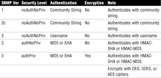
At the noAuthNoPriv security level, SNMP v3 uses a username. SNMP v3 is downward-compatible with SNMP v1 and v2 if the username only is used. The username remains cleartext, as is the case with the community string in SNMP v1 and v2.
Note
HMAC = Hashing Message Authentication Code. SHA (Secure Hashing Algorithm) and MD5 (Message Digest 5) are examples. DES (Date Encryption Standard), 3DES (Triple-DES), and AES (Advanced Encryption Standard) are all examples of encryption algorithms or ciphers. We examine these in Chapter 6, “Introducing Cryptographic Services.”
To enable the SNMP agent on the IOS router and configure it to respond to SNMP gets, follow these steps in the Cisco SDM:
-
Choose Configure->Additional Tasks->Router Properties->SNMP starting at the SDM homepage.
-
Click the Edit button, as shown in Figure 4.4.
-
Check the Enable SNMP checkbox in the SNMP Properties pane.
-
As shown in Figure 4.4, click Add and fill in the Community String in the Community String dialog box. Click either the Read-Only or Read-Write radio buttons.
-
Click OK.

While we’re at the SNMP settings page, we can set up a trapping receiver for unsolicited SNMP messages to an SNMP server:
-
Starting at the SNMP pane in Cisco SDM, click Edit. The SNMP Properties window displays, as shown in Figure 4.5.
-
Click Add to add a new trap receiver in the Trap Receiver section of the SNMP Properties window.
-
Enter the IP address (or hostname) and password of the NMS, which is acting as the trap receiver.
-
Click OK to finish adding the trap receiver.

In order to ensure that management sessions to the router are confidential, Secure Shell (SSH) is recommended. With respect to the reference architecture in Figure 4.1, SSH could be used to the Catalyst switch and the IOS firewall.
SSH is essentially encrypted Telnet. As such, it should be used instead of Telnet wherever possible, particularly where in-band management of a device is required. There are two versions of SSH:
![]() Version 1. Cisco IOS Release 12.1(1)T and later.
Version 1. Cisco IOS Release 12.1(1)T and later.
![]() Version 2. Cisco IOS Release 12.3(4)T and later. This is more secure than version 1.
Version 2. Cisco IOS Release 12.3(4)T and later. This is more secure than version 1.
Note
Beginning with Cisco IOS Release 12.1(3)T, the router can act both as a server and a client. The ssh command can be used to launch a client SSH session to an SSH server.
The following are prerequisite tasks for enabling SSH using Cisco SDM:
![]() Ensure that you have the right release of the Cisco IOS Software image. Only images that contain the IPsec feature set will support the SSH daemon.
Ensure that you have the right release of the Cisco IOS Software image. Only images that contain the IPsec feature set will support the SSH daemon.
Note
Typically, IOS images whose names have the string “k8” or “k9” in them are crypto images that support cryptosystems such as IPsec VPNs and the SSH daemon. There are a number of ways that you can determine the image name. One way is the show flash command:
ciscoISR#show flash
28672K bytes of processor board System flash (Intel Strataflash)
Directory of flash:/
2 -rwx 18929780 May 15 2008 21:15:14 -04:00 c870-advipservicesk9-
mz.124-15.T5.bin
![]() The target systems must be configured with AAA (either local or external) because SSH requires the use of a username and password.
The target systems must be configured with AAA (either local or external) because SSH requires the use of a username and password.
![]() Ensure that target systems have unique fully-qualified domain names (FQDNs) if you are using the device’s FQDN to SSH to.
Ensure that target systems have unique fully-qualified domain names (FQDNs) if you are using the device’s FQDN to SSH to.
![]() The domain name must also be set on any device running the SSH daemon because the RSA keys (see the following steps) will not generate without the domain name set.
The domain name must also be set on any device running the SSH daemon because the RSA keys (see the following steps) will not generate without the domain name set.
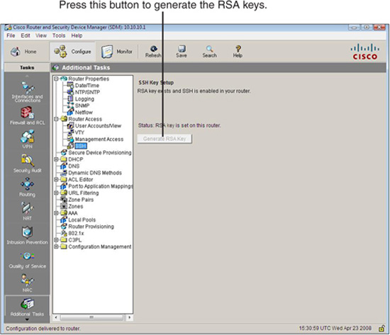
Using the Cisco SDM, follow these steps to enable SSH on the IOS router:
-
Choose Configure->Additional Tasks->Router Access->SSH.
-
If the Generate RSA Key button is grayed out (as shown in Figure 4.6), this means that the RSA key exists and SSH is enabled on the router. If the Generate RSA Key button is available, press it and follow the prompts to generate a key with a modulus between 512 and 2048 in 64-bit increments. The larger the modulus, the longer it will take to generate the key.
-
Click OK.
Note
SSH is enabled by default on the LAN interface on Cisco IOS routers that ship with the Cisco SDM pre-installed.
Rivest-Shamir-Addleman (RSA) keys are discussed in Chapter 6.
-
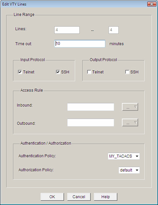
Now that we have the SSH daemon operational, we should be able to SSH to it, right? Wrong! Remember what we do with policies; we have to apply them somewhere. SSH has to be enabled on the vty lines. This is accomplished in the Cisco SDM by choosing Configure->Additional Tasks->Router Access->VTY. Figure 4.7 shows the Edit VTY Lines dialog box.
Here are the equivalent CLI commands:
CiscoISR(config)#ip domain-name example.com
CiscoISR(config)#crypto key zeroize rsa
% All RSA keys will be removed.
% All router certs issued using these keys will also be removed.
Do you really want to remove these keys? [yes/no]: yes
CiscoISR(config)#crypto key generate rsa general-key modulus 1024
The name for the keys will be: CiscoISR.example.com
% The key modulus size is 1024 bits
% Generating 1024 bit RSA keys, keys will be non-exportable...[OK]
CiscoISR(config)#ip ssh time-out 120
CiscoISR(config)#ip ssh authentication-retries 4
CiscoISR(config)#line vty 0 4
CiscoISR(config-line)#transport input ssh
CiscoISR(config-line)#end
CiscoISR#
The Cisco SDM enables you to manually:
![]() Synchronize the router’s clock to the local PC clock.
Synchronize the router’s clock to the local PC clock.
![]() Edit the router’s date and time.
Edit the router’s date and time.
Assuming that our security policy requires that all of our network devices have their clocks synchronized to a single, recognized time source, manual setting of the router clock is not an option. We will choose to set the router’s clock with a Network Time Protocol (NTP) source. An organization can set up its own master time source (preferably OOB) or synchronize from a public time server on the Internet.
A few important notes:
![]() NTP uses UDP port 123 and is considered secure.
NTP uses UDP port 123 and is considered secure.
![]() Simple Network Time Protocol (SNTP) is a simpler and less secure version of NTP.
Simple Network Time Protocol (SNTP) is a simpler and less secure version of NTP.
![]() NTP version 3 (NTPv3) and above implement cryptography and authentication between NTP peers (client and server).
NTP version 3 (NTPv3) and above implement cryptography and authentication between NTP peers (client and server).
You must be careful when synchronizing from an NTP server. Rules of evidence might require you to prove that you are using an unimpeachable source of information to synchronize your devices’ clocks if you want to use your logs in the course of a criminal proceeding. This makes using Internet time sources problematic. This might be mitigated somewhat by using your own master time server, but if you are synchronizing it from an Internet time source, you are back to where you started. Therefore, your master time server may need to be synchronized by radio or satellite to meet the security standards required by the security policy.
Figure 4.8 illustrates the steps to add an NTP server using the SDM. Starting at the Cisco SDM homepage, here are the steps required to add an NTP server:
-
Choose Configure->Additional Tasks->Router Properties->NTP/SNTP.
-
Click Add to add a new NTP server. The Add NTP Server Details window appears.
-
Fill in the details about your NTP server in the Add NTP Server Details window.
![]() (optional) You can select the source interface for your NTP packets from the NTP Source Interface drop-down box.
(optional) You can select the source interface for your NTP packets from the NTP Source Interface drop-down box.
![]() (optional) If this is the preferred NTP server, check the Prefer check box. This server will be checked before other servers. You can have more than one preferred server.
(optional) If this is the preferred NTP server, check the Prefer check box. This server will be checked before other servers. You can have more than one preferred server.
4. Check the Authentication Key check box if the NTP server requires authentication and fill in the values.
5. To finish adding the server, click OK.

Cisco routers come with services enabled on them by default that make them great routers, but not necessarily great security devices. The reasons for these default services are various, but generally speaking, they are there more for historical reasons than anything else and would not likely be the defaults were these devices to be given a rethink in the context of current security knowledge. In this section, we quickly summarize some of these default services, their security risk in the context of the router’s responsibilities as a perimeter defense device, and (more importantly) what to do about it. As we will see, the router has a number of CLI and SDM tools that can first audit and secondly secure these vulnerabilities.
The following is a list of general recommendations for router services and interfaces that are vulnerable to network attacks. They can be grouped into seven categories, as follows:
![]() Disable unnecessary services and interfaces.
Disable unnecessary services and interfaces.
![]() Disable commonly configured management services.
Disable commonly configured management services.
![]() Ensure path integrity.
Ensure path integrity.
![]() Disable probes and scans.
Disable probes and scans.
![]() Ensure terminal access security.
Ensure terminal access security.
![]() Disable gratuitous and proxy ARP.
Disable gratuitous and proxy ARP.
![]() Disable IP directed broadcasts.
Disable IP directed broadcasts.
Table 4.3 outlines Cisco’s recommendations for disabling vulnerable router services and interfaces.
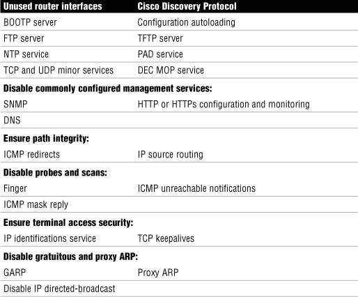
A detailed explanation of the vulnerabilities presented by these features will not be attempted. What follows is a quick summary of the services and their respective vulnerabilities as well as security recommendations.
The following are Cisco’s recommendations for disabling unnecessary services and interfaces:
![]() Router Interfaces. Disabling unused router interfaces will limit unauthorized access to both the router and the network.
Router Interfaces. Disabling unused router interfaces will limit unauthorized access to both the router and the network.
Recommendation: Disable unused open router interfaces.
![]() Bootstrap Protocol (BOOTP). This service is enabled by default. It allows other devices to obtain IP addresses and other configuration information automatically.
Bootstrap Protocol (BOOTP). This service is enabled by default. It allows other devices to obtain IP addresses and other configuration information automatically.
Recommendation: This service is rarely needed and should be disabled.
![]() Cisco Discovery Protocol. Enabled by default. This protocol allows the router to discover information about directly connected neighbor Cisco devices.
Cisco Discovery Protocol. Enabled by default. This protocol allows the router to discover information about directly connected neighbor Cisco devices.
Recommendation: This service is not required once a network has been constructed and tested. Disable.
![]() Configuration Autoloading. Disabled by default. It allows the autoloading of configuration files from a network server.
Configuration Autoloading. Disabled by default. It allows the autoloading of configuration files from a network server.
Recommendation: Disable unless needed.
![]() FTP Server. Disabled by default. Allows the router to act as an FTP server and serve files from flash memory to FTP clients.
FTP Server. Disabled by default. Allows the router to act as an FTP server and serve files from flash memory to FTP clients.
Recommendation: Disable unless needed.
![]() TFTP Server. Disabled by default. Allows the router to act as a TFTP server and serve files from flash memory to TFTP clients.
TFTP Server. Disabled by default. Allows the router to act as a TFTP server and serve files from flash memory to TFTP clients.
Recommendation: Disable unless needed
![]() Network Time Protocol (NTP) Service. This protocol was discussed in the last section, as were recommendations for its use.
Network Time Protocol (NTP) Service. This protocol was discussed in the last section, as were recommendations for its use.
Recommendation: Disable unless needed.
![]() TCP and UDP Minor Services. These services are disabled by default in Cisco IOS Software Release 11.3 and later. They are small daemons that have a diagnostic purpose but are rarely needed.
TCP and UDP Minor Services. These services are disabled by default in Cisco IOS Software Release 11.3 and later. They are small daemons that have a diagnostic purpose but are rarely needed.
Recommendation: Disable this service explicitly.
![]() Maintenance Operation Protocol (MOP) Service. Enabled by default on most Ethernet interfaces. It is a legacy Digital Electronic Corporation (DEC) maintenance protocol.
Maintenance Operation Protocol (MOP) Service. Enabled by default on most Ethernet interfaces. It is a legacy Digital Electronic Corporation (DEC) maintenance protocol.
Recommendation: Disable this service explicitly when it is not in use.
The following are Cisco’s recommendations for disabling and restricting commonly configured management services:
![]() Simple Network Management Protocol (SNMP). Enabled by default. This protocol’s vulnerabilities (SNMP versions 1 and 2) were discussed in a previous section in this chapter.
Simple Network Management Protocol (SNMP). Enabled by default. This protocol’s vulnerabilities (SNMP versions 1 and 2) were discussed in a previous section in this chapter.
Recommendation: Disable this service when it is not required.
![]() HTTP or HTTPS Configuration and Monitoring. Default operation is device-dependent. Used for monitoring and configuring the device using a web browser and/or Cisco SDM.
HTTP or HTTPS Configuration and Monitoring. Default operation is device-dependent. Used for monitoring and configuring the device using a web browser and/or Cisco SDM.
Recommendation: Disable if not in use or restrict access using ACLs.
![]() Domain Name System (DNS). Enabled by default. Also by default, the DNS client broadcasts its request to destination IP address 255.255.255.255. This makes it vulnerable to spoofed responses, possibly leading to session-hijacking.
Domain Name System (DNS). Enabled by default. Also by default, the DNS client broadcasts its request to destination IP address 255.255.255.255. This makes it vulnerable to spoofed responses, possibly leading to session-hijacking.
Recommendation: Disable if not required. If it is required, set the DNS lookup service with the unicast address of specific DNS servers.
The following are Cisco’s recommendations for ensuring path integrity. Path integrity ensures that the path that data packets take through the network is not somehow redirected or otherwise compromised by an exploit:
![]() Internet Control Message Protocol (ICMP) redirects. Enabled by default. When a router receives an ICMP redirect on an interface, it is required to resend the packet out the same interface that it was received. If this is an Internet-facing interface, an attacker could use the resent information to redirect packets to an untrusted device, a classic session hijacking exploit.
Internet Control Message Protocol (ICMP) redirects. Enabled by default. When a router receives an ICMP redirect on an interface, it is required to resend the packet out the same interface that it was received. If this is an Internet-facing interface, an attacker could use the resent information to redirect packets to an untrusted device, a classic session hijacking exploit.
Recommendation: Disable this service if it is not required.
![]() IP source routing. Enabled on interfaces by default. Routing is normally destination-based, but a IP host can indicate which path it would prefer to take through a network by specifying IP source-routing options in the IP packet header. Routers would be forced to honor this path. This can be exploited by an attacker as a carefully crafted attack that would take the attacker’s choice of path through an unprotected network rather than the best path indicated in the routing table.
IP source routing. Enabled on interfaces by default. Routing is normally destination-based, but a IP host can indicate which path it would prefer to take through a network by specifying IP source-routing options in the IP packet header. Routers would be forced to honor this path. This can be exploited by an attacker as a carefully crafted attack that would take the attacker’s choice of path through an unprotected network rather than the best path indicated in the routing table.
Recommendation: Disable this service on all interfaces unless it is required.
The following are Cisco’s recommendations for disabling probes and scans of the network and the router itself:
![]() Finger Service. Enabled by default. Finger service allows a reconnaissance of the router to determine a list of users currently using a particular device, among other information.
Finger Service. Enabled by default. Finger service allows a reconnaissance of the router to determine a list of users currently using a particular device, among other information.
Recommendation: Disable this service if it is not required.
![]() ICMP Unreachable Notifications. Enabled by default. This service notifies users of unreachable IP hosts and networks. It can be used during a reconnaissance attack to map out a network’s topology because if the attacker doesn’t receive an ICMP unreachable notification in reply to an ICMP request, they can infer that the network is reachable.
ICMP Unreachable Notifications. Enabled by default. This service notifies users of unreachable IP hosts and networks. It can be used during a reconnaissance attack to map out a network’s topology because if the attacker doesn’t receive an ICMP unreachable notification in reply to an ICMP request, they can infer that the network is reachable.
Recommendation: An attacker can infer all they want! Turn off ICMP unreachable notifications on all interfaces facing untrusted networks unless they are required.
![]() ICMP Mask Reply. Disabled by default. Same general vulnerabilities as ICMP unreachables.
ICMP Mask Reply. Disabled by default. Same general vulnerabilities as ICMP unreachables.
Recommendation: Turn off ICMP mask replies on all interfaces facing untrusted networks unless they are required.
The following are Cisco’s recommendations for ensuring terminal access security. These recommendations will mitigate the possibility that an attacker can identify the device and launch certain DoS attacks against the device itself:
![]() IP Identification (IDENT) Service. Enabled by default. Useful in reconnaissance attacks. When TCP port 113 is probed, the identity of the device is obtained.
IP Identification (IDENT) Service. Enabled by default. Useful in reconnaissance attacks. When TCP port 113 is probed, the identity of the device is obtained.
Recommendation: Disable explicitly.
![]() TCP Keepalives. Disabled by default. This service is a reaper service that polls TCP sessions to see if they are still active. If a response isn’t received, the connection is closed, thereby freeing up resources on the router and preventing certain DoS attacks.
TCP Keepalives. Disabled by default. This service is a reaper service that polls TCP sessions to see if they are still active. If a response isn’t received, the connection is closed, thereby freeing up resources on the router and preventing certain DoS attacks.
Recommendation: Should be enabled globally.
The following are Cisco’s recommendations for disabling gratuitous and proxy address resolution protocol (ARP) messages.
![]() Gratuitous ARP (GARP). Enabled by default. It is commonly used in ARP poisoning attacks. It is gratuitous in that they are ARP replies that don’t match ARP requests. The intent is to fool IP hosts to cache these replies in their ARP tables so that the host will send packets to the attacker versus the legitimate hosts whose IP addresses and MAC addresses the attacker has spoofed.
Gratuitous ARP (GARP). Enabled by default. It is commonly used in ARP poisoning attacks. It is gratuitous in that they are ARP replies that don’t match ARP requests. The intent is to fool IP hosts to cache these replies in their ARP tables so that the host will send packets to the attacker versus the legitimate hosts whose IP addresses and MAC addresses the attacker has spoofed.
Recommendation: Should be disabled on each interface unless it is needed.
![]() Proxy ARP. Enabled by default. This service allows the router to reply to an ARP request by proxy with its own MAC address where an IP address resolves to a remote segment.
Proxy ARP. Enabled by default. This service allows the router to reply to an ARP request by proxy with its own MAC address where an IP address resolves to a remote segment.
Recommendation: Should be disabled unless the router is acting as a layer 2 LAN bridge.
Now that we have identified the specific vulnerabilities that may be present on the router, we will perform a security audit of the router using the Cisco SDM, as well as some CLI tools.
The Cisco SDM Security Audit, shown in Figure 4.9, is based on the Cisco IOS AutoSecure feature (also accessible by the CLI, as we will see later), which is an automated, interactive script that checks for vulnerabilities and recommends how they might be remediated. As we will see, the Cisco SDM Security Audit has almost all the feature of the Cisco AutoSecure functions.
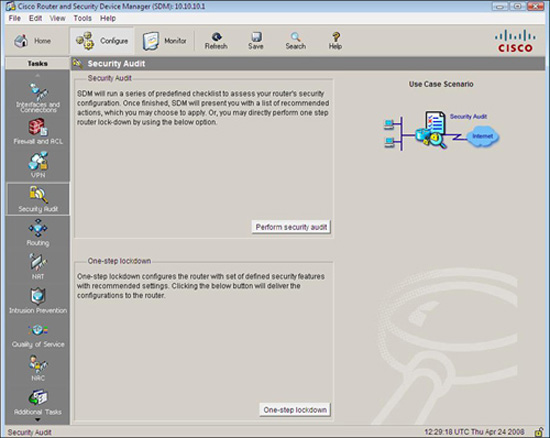
The Security Audit Wizard can be reached by choosing Configure->Security Audit from the Cisco SDM homepage. There are two modes of operation, as indicated in Figure 4.9:
![]() Security Audit Wizard. Once vulnerabilities are discovered, the wizard gives you a choice as to which vulnerabilities you want to secure. Press the Perform security audit button if you want this.
Security Audit Wizard. Once vulnerabilities are discovered, the wizard gives you a choice as to which vulnerabilities you want to secure. Press the Perform security audit button if you want this.
![]() One-Step Lockdown. This configures the router with a set of defined security features with recommended settings in one step and without further user interaction. Press the One-step lockdown button if you want this.
One-Step Lockdown. This configures the router with a set of defined security features with recommended settings in one step and without further user interaction. Press the One-step lockdown button if you want this.
Let’s examine the Cisco SDM Security Audit Wizard first.
In the last section, we identified the specific vulnerabilities that may be present on the router. Now we will use the Cisco SDM Security Audit Wizard to determine whether they are present and give us the option to remedy them.
To perform a security audit, follow these steps from the Cisco SDM homepage:
-
Choose Configure->Security Audit.
-
Click the Perform Security Audit button. The Welcome Page of the Security Audit Wizard appears.
-
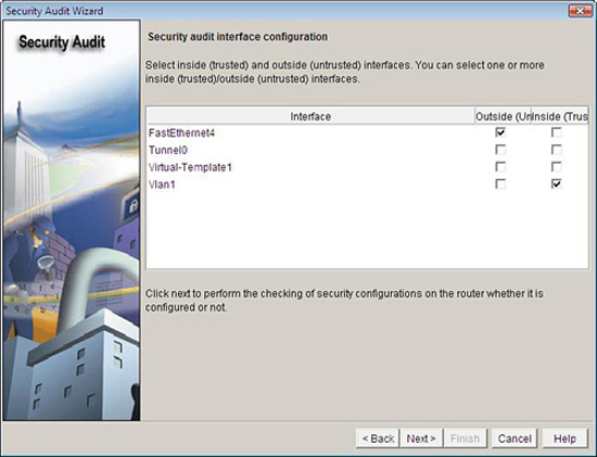
Click Next to bring up the Security Audit Interface Configuration page as shown in Figure 4.10.
-
Before the audit proceeds, the Security Audit Wizard needs to know which interfaces connect to the outside and which interfaces connect to the inside. Beside each interface listed, check the Inside or Outside check box. (This makes sense because some of the vulnerabilities listed previously depend on whether the interface is connected to a hostile network or not.)
-
Click Next.
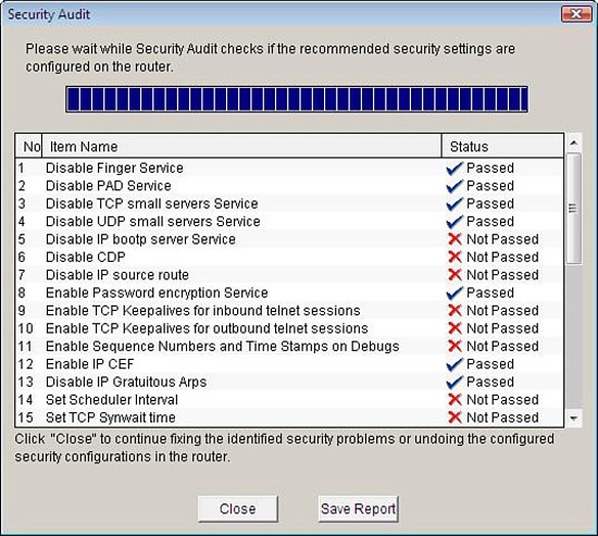
The Security Audit report window appears, which runs an audit, finishing with an itemized report detailing the number, item name, and status of the potential vulnerabilities, as shown in Figure 4.11. A check mark will appear if the item has passed. An X will appear if the item has not passed.
-
If you want to save the report to a file, click Save Report.
-
To continue with fixing the identified security issues, click Close.
-
The Security Audit Wizard window appears, as shown in Figure 4.12. If you want to fix the security problems identified, you can either check the Fix it check box in the Action column beside each identified security problem you want to fix, or you can click the Fix All button, which checks all the boxes for you.
If you want to undo security problems that have been identified as “Passed” in the Security Audit report window (refer to Step 5), you can choose Undo Security configurations in the Select an option drop-down list at the top of the Security Audit window. The resulting Security Audit Wizard window will allow you to check off Undo in the Action column beside each enabled security configuration you want to undo.
-
Click Next.
-
Depending on which security vulnerabilities you have chosen to fix, you might be asked to enter more information on the subsequent screens. Enter the required information and click Next as indicated until you arrive at the Summary screen.
-
Click Finish to deliver the changes to the router.

The Cisco one-step lockdown feature can be executed using either the Cisco SDM or the CLI command, auto secure. Complete the following steps to perform a one-step lockdown using the Cisco SDM, starting at the SDM homepage:
-
Choose Configure->Security Audit->One-step lockdown.
-
An SDM Warning dialog appears, as shown in Figure 4.13. Click Yes if you are sure you want to lock down the router. A one-step lockdown window appears with a check mark beside all the items that will be fixed.
-
Click Deliver to deliver the configuration changes to the router.
-
Click OK to exit back to the Security Audit window.

Cisco AutoSecure is a feature that is initiated from the CLI and executes a script, which first makes recommendations for fixing security vulnerabilities, and then modifies the security configuration of the router. The syntax of the command is as follows:
auto secure [no-interact]
It can be executed in either of two modes:
![]() Interactive Mode. Prompts the user with recommendations for enabling and disabling specific services. This is the default mode. Use the auto-secure command with no options.
Interactive Mode. Prompts the user with recommendations for enabling and disabling specific services. This is the default mode. Use the auto-secure command with no options.
![]() Non-Interactive Mode. Automatically executes the Cisco AutoSecure command with Cisco’s recommended default settings. Use the auto secure no-interact form of the command.
Non-Interactive Mode. Automatically executes the Cisco AutoSecure command with Cisco’s recommended default settings. Use the auto secure no-interact form of the command.
Here is what the opening dialog looks like. This example is using the interactive mode:
ciscoISR#auto secure
— - AutoSecure Configuration — -
***AutoSecure configuration enhances the security of
the router, but it will not make it absolutely resistant
to all security attacks***
AutoSecure will modify the configuration of your device.
All configuration changes will be shown. For a detailed
explanation of how the configuration changes enhance security
and any possible side effects, please refer to Cisco.com for
Autosecure documentation.
At any prompt you may enter '?' for help.
Use ctrl-c to abort this session at any prompt.
Gathering information about the router for AutoSecure
Is this router connected to internet? [no]:yes
[output omitted]
Securing Management plane services...
Disabling service finger
Disabling service pad
Disabling udp&tcp small servers
Enabling service password encryption
Enabling service tcp-keepalives-in
Enabling service tcp-keepalives-out
Disabling the cdp protocol
Disabling the bootp server
Disabling the http server
Disabling the finger service
Disabling source routing
Disabling gratuitous arp
Configure NTP Authentication? [yes]:no
Configuring AAA local authentication
Configuring Console, Aux and VTY lines for
local authentication, exec-timeout, and transport
Securing device against Login Attacks
Configure the following parameters
Blocking Period when Login Attack detected: 120
At the end of the AutoSecure interactive dialog, the recommended running-config with the changes to be applied is displayed. You are then asked:
Apply this configuration to running-config? [yes]:yes
Note
Once applied to the running-config, if you lose connectivity to the router or something stops working, you can always reboot the router because the changes will not have been saved to the startup-config. This sounds strange, but many security texts recommend this procedure. Essentially if you don’t know what a service does, turn it off. If something important stops working as a result, you now know what it does. Locking down a network device, despite the excellent features such as AutoSecure, is often a trial-and-error approach.
You should consider testing these changes in a lab environment first, and only make changes on a production network when you are absolutely sure of what you are doing.
There are some notable limitations and differences between Cisco AutoSecure and the Cisco SDM Security Audit:
![]() Cisco SDM does not implement the following Cisco AutoSecure features:
Cisco SDM does not implement the following Cisco AutoSecure features:
![]() Disabling NTP
Disabling NTP
![]() Configuring AAA
Configuring AAA
![]() Setting SPD values
Setting SPD values
![]() Enabling TCP intercepts
Enabling TCP intercepts
![]() Configuring anti-spoofing ACLs on outside-facing interfaces
Configuring anti-spoofing ACLs on outside-facing interfaces
![]() Cisco SDM implements some Cisco AutoSecure features differently:
Cisco SDM implements some Cisco AutoSecure features differently:
![]() SNMP is disabled but will not configure SNMPv3 (varies with router).
SNMP is disabled but will not configure SNMPv3 (varies with router).
![]() SSH is enabled and configured with Cisco IOS images that support this feature.
SSH is enabled and configured with Cisco IOS images that support this feature.
![]() Curiously, Secure Copy Protocol (SCP) is not enabled and unsecure FTP is.
Curiously, Secure Copy Protocol (SCP) is not enabled and unsecure FTP is.