
This appendix provides a summary of the modeling conventions used in this book. In particular, we focus on the use of the UML, and on the model structures that have been recommended and described in Chapters 6–9.
In this section, we provide a summary of the UML representation of the elements in the J2EE Developer Roadmap. The content of this section is derived from a number of sources. In particular, the conventions for modeling EJBs have been derived from Java Specification Request 26 (JSR 26), which has been defined by the Java Community Process. The conventions for modeling other J2EE elements, such as JSPs and servlets, have been derived from the work of Jim Conallen (Conallen 2000) and internal initiatives within Rational Software.
| Artifact | UML Representation | Examples | Stereotype(s) |
|---|---|---|---|
| Actor | Actor | None | |
| Glossary | None | N/A | N/A |
| Software Architecture Document | None | N/A | N/A |
| Supplementary Specification | None | N/A | N/A |
| Use-Case Model[1] | Model | «use-case model» | |
| Use Case | None | ||
| Package | None | ||
| Use-Case Priority List | None | N/A | N/A |
[1] The tables containing artifacts show subartifacts (artifacts contained within another artifact) after the parent artifact with their name preceded by a “ | |||
| Artifact | UML Representation | Examples | Stereotype(s) |
|---|---|---|---|
| Deployment Model | Model | «deployment model» | |
| Design Model | Model | «design model» | |
| Class | Boundary Class | «boundary» | |
| Control Class | «control» | ||
| Entity Class | «entity» | ||
| Package | None | ||
| Layer | «layer» | ||
| Collaboration Instance | «use-case realization» | ||
| Software Architecture Document | None | N/A | N/A |
| User-Experience Model | Model | «user-experience model» | |
| Class Diagram(s) | None | ||
| Class | «screen» | ||
| Collaboration Instance | «use-case storyboard» |
| Artifact | UML Representation | Examples | Stereotype(s) |
|---|---|---|---|
| Data Model | Model | «data model» | |
| Deployment Model | Model | «deployment model» | |
| Design Model | Model | «design model» | |
| Class | None | ||
| EJB Implementation Class | «EJBImplementation» | ||
| EJB Primary Key Class | None | ||
| HTML Form | «HTMLForm» | ||
| HTML Page | «ClientPage» | ||
| JSP | «ServerPage» | ||
| Servlet | «HttpServlet» «GenericServlet» | ||
| Package | None | ||
| Layer | «Layer» | ||
| Subsystem | None | ||
| Enterprise Component | «EnterpriseComponent» | ||
| Component | None | ||
| Component | EJB | «EJBSessionBean» «EJBEntityBean» «EJBMessageDrivenBean» | |
| Interface | None | ||
| Class[2] | EJB Interface | «EJBRemoteInterface» «EJBSessionHomeInterface» «EJBEntityHomeInterface» «EJBLocalInterface» «EJBSessionLocalHomeInterface» «EJBEntityLocalHomeInterface» | |
| Java Interface | «JavaInterface» | ||
| Collaboration Instance | «use-case realization» | ||
| Software Architecture Document | None | N/A | N/A |
[2] A UML Class is used to represent a Java Interface since a Java interface is not the same as a UML interface (for example, a Java interface may have attributes). | |||
| Artifact | UML Representation | Examples | Stereotype(s) |
|---|---|---|---|
| Implementation Model | Model | «implementation model» | |
| Artifact | None | ||
| Deployment Descriptor | «ApplicationDescriptor» «ApplicationClientDescriptor» «EJBDescriptor» «WebDescriptor» | ||
| HTML file | None | ||
| Java Bytecode File | «JavaClassFile» | ||
| Java Source File | None | ||
| J2EE Module | «EAR» «EJB-JAR» «JAR» «WAR» | ||
| JSP File | «JSPFile» | ||
| Package | None | ||
| Java Package | None | ||
| Virtual Directory | «VirtualDirectory» | ||
| Software Architecture Document | None | N/A | N/A |
The following table summarizes the J2EE-specific relationships that may occur between Design Model elements.
| UML Representation | Examples | Stereotype(s) | |
|---|---|---|---|
| Between | And | ||
| Association | HTML page | HTML page or JSP | «HTMLLink» |
| JSP | HTML page | «Build» | |
| HTML form | JSP | «Submit» | |
| JSP | JSP | «JSPInclude» «JSPForward» | |
| Aggregation | HTML page | HTML form | «Build» |
| Dependency | EJB | EJB element | «reside» |
| EJB implementation class | EJB home interface | «EJBRealizeHome» | |
| EJB implementation class | EJB remote interface | «EJBRealizeRemote» | |
| EJB implementation class | EJB local interface | «EJBRealizeLocal» | |
| EJB implementation class | EJB local home interface | «EJBRealizeLocalHome» | |
The following table summarizes the J2EE-specific stereotypes that can be applied to the attributes and operations of a Design Class.
| UML Representation | Element | Stereotype |
|---|---|---|
| Attribute | EJB CMP field | «EJBCmpField» |
| EJB primary key field | «EJBPrimaryKeyField» | |
| HTML input field | «HTMLInput» | |
| HTML select field | «HTMLSelect» | |
| HTML submit button | «HTMLSubmit» | |
| HTML text area | «HTMLTextArea» | |
| Operation | EJB business method | «EJBBusinessMethod» |
| EJB create method | «EJBCreateMethod» | |
| EJB finder method | «EJBFinderMethod» | |
| EJB home method | «EJBHomeMethod» | |
| EJB select method | «EJBSelectMethod» |
In this section, we describe some recommendations for structuring the content of the J2EE Developer Roadmap models. For more information on how to define the content of these models, and the rationale for this structure, see the process chapters (Chapters 6–9).
The model structures described in this section have been used throughout the book and in the sample application. They can be replaced by any number of equally valid structures without affecting the process.
The recommended structure of the Use-Case Model is shown in Figure B.1. This structure is described in Chapter 6, Requirements.

The recommended structure for the User-Experience Model is shown in Figure B.2. This structure is described in Chapter 7, Analysis.
The recommended structure of the Design Model is shown in Figure B.3. This structure is initially described in Chapter 7, and is then refined in Chapter 8, Design.

The analysis activities result in the population of the “Analysis Elements” and “Key Abstractions” packages. The structure of these packages is shown in Figure B.4. This structure is described in Chapter 7.

The structure of the “Presentation” layer is shown in Figure B.5. This structure is described in Chapter 8.

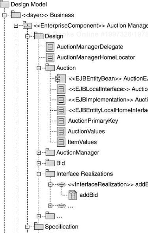
The structure of the “Business” layer is shown Figure B.6. This structure is described in Chapter 8.
The structure of the “Use-Case Realizations” package is shown in Figure B.7. This structure is described in Chapter 8.

The Implementation Model comprises a number of structures that are discussed in Chapter 9, Implementation, namely:
A structure to describe elements that are organized by Java package (see Figure B.8)
A structure to describe elements that are organized within a virtual directory (see Figure B.9)
A structure to describe deployment elements (see Figure B.10)


Java Packaging Structure. The Java packaging structure is shown in Figure B.8. This structure is described in Chapter 9.
Virtual Directory Structure. The virtual directory structure is shown in Figure B.9. This structure is described in Chapter 9.
Deployment Elements Structure. The structure to support deployment elements is shown in Figure B.10. This structure is described in Chapter 9.