
Setting up paper space layouts
Buttons or tabs for layout fashionistas
Looking into viewports
Working in paper space
Most of what the earlier chapters look at revolves around setting up the model space environment — that infinitely large, three-dimensional realm wherein you create your gleaming towers, your wondrous electronic gadgetry ... or your garden shed or your angle bracket. However, you may have picked up a hint here or there that AutoCAD has a whole different environment known as paper space.
The final product of all this setup, remember, is a printed drawing on a piece of paper. Unless you're prepared to send your computer out to the work site, you're going to have to get those designs off the screen and onto paper. The first part of that process is configuring the sheet layout in paper space, which I explain in this chapter. For the actual process of outputting either model space or layouts to printer or plotter, see Chapter 16.
Chapter 2 introduces you to the two spaces — model and paper — and Chapter 4 explains how to configure model space for efficient drawing. Before you plunge into paper space, a quick recap of model space is in order.
Note
Model space is the drawing environment that's current when the Model tab (not the Model button) on the status bar is active. Model space is where you create the "real" objects that you're drawing, so these objects are referred to as model geometry whether they're 2D or 3D entities. When the Model tab is active, you see objects in model space only — anything in paper space is invisible.
Tip
In AutoCAD 2010, it's still possible to ignore paper space layouts entirely and do all your drawing and plotting in model space. But you owe it to yourself to give layouts a try. You'll probably find that they make plotting more consistent and predictable. They'll give you more plotting flexibility when you need it. And you'll certainly encounter drawings from other people that make extensive use of paper space, so you need to understand it if you plan to exchange drawings with anyone else.
A paper space layout is a representation of a drawing sheet. Although the model geometry — the real stuff — goes in model space, the "not-real" drawing objects (for example, a drawing border, title block, general notes, perhaps view labels, and symbols like North arrows) all go in paper space on the layout. Where model space is like the world, infinitely large and three-dimensional, paper space is finite — the size of a drawing sheet, in fact — and two-dimensional, just like a drawing sheet.
Aside from just an arrangement of your drawing sheet, layouts also store plot information. AutoCAD saves separate plot settings with each layout as well as model space so that you can plot each one differently. In practice, you'll probably need to use only one of the paper space layout tabs, especially when you're getting started with AutoCAD.
Rather than just reading about it, you may also want to open a few of the AutoCAD 2010 sample drawings and click the Model and Layout buttons or tabs to witness the variety of ways in which paper space is used.
Note
The AutoCAD and AutoCAD LT sample drawings are no longer installed with the program, but they're still available — online. Download them from www.autodesk.com/autocad-samples or www.autodesk.com/autocadlt-samples. The upside of the change is that users of either program now have access to the other's sample files.
The Autodesk documentation sometimes refers to the Model tab, or to layout tabs, and sometimes (like just a second ago) I do here as well. If you're working in the AutoCAD Classic workspace, you do see actual, selectable tabs at the lower-left edge of the drawing window, clearly labeled Model, Layout1, and Layout 2 (refer to Figure 2-2 in Chapter 2). The 2D Drafting & Annotation workspace — the workspace I favor in this book — replaces those tabs with the Model and Layout buttons near the middle of the status bar.
If you want to see the actual tabs, and you're in the 2D Drafting & Annotation workspace — or if you're staying in AutoCAD Classic and want the buttons — the following steps explain how to switch between the two systems and view the drawing layouts in each. If you see Model and Layout tabs at the lower-left edge of the drawing area, go to Step 4.
If your status bar shows the Model and Layout buttons, right-click either button and choose Display Layout and Model Tabs.
At least one labeled tab will appear at the lower-left edge of the drawing window. Depending on the drawing you're viewing, you may need to click the little black left-pointing arrow until you see the first tab, labeled Model.
Without clicking anything, move the mouse pointer over the Model and Layout tabs.
A preview image of the layout or model space appears near the tab. As you move across the tabs, the preview changes, letting you visually identify the layout you want.
Click a layout tab to make that layout current.
The selected layout fills the drawing window.
Tip
You can rename layout tabs — but not the Model tab — by double-clicking the layout name twice to open an edit box.
To switch from tabs to buttons, proceed as follows:
Right-click the Model tab or any layout tab and choose Hide Layout and Model Tabs.
The tabs disappear, and the Model and Layout buttons appear on the status bar.

Selecting Model sets AutoCAD's full-screen model space environment current, hiding any paper space layout objects.

Note that the Layout button's tooltip doesn't say Layout but instead lists the actual layout name. (The default layout names are Layout1 and Layout 2.) Whichever layout was activated last appears in the drawing window.

Where hovering over Model and Layout tabs displays an image of their contents, you have to launch a new command — Quick View Layouts — to preview the drawing's layouts. I describe the new Quick View Layouts feature more fully in the following section.
Click a layout's preview image to make the layout current.
The selected layout is activated and fills the drawing window.
Warning
Of course, you can work in any configuration you please — for example, you may like the AutoCAD Classic workspace but prefer Model/Layout buttons instead of tabs. However, if you switch workspaces and then go back to AutoCAD Classic, the change you made from tabs to buttons will not be retained. For information on saving your own custom workspace, look up workspace in the online help system.
Quick View Layouts is the second of two AutoCAD 2010 features that use the Quick View image strip to display preview images of drawings or layouts. I introduce Quick View Drawings — which previews all your open drawings in the Quick View strip — in Chapter 2.
In earlier versions of AutoCAD, with buttons enabled rather than tabs, you would right-click the Layout button to open a shortcut menu listing the drawing's layouts. But mere words in a menu are so previous release! The following steps explain how to change between model space and a layout or switch between layouts:
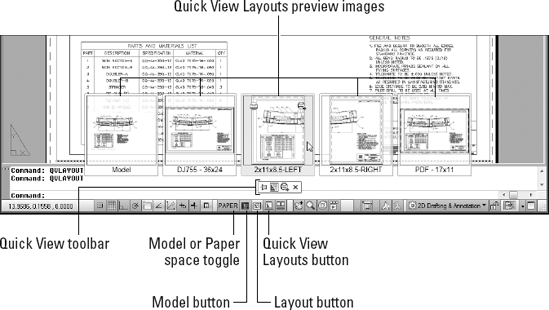
Click the Quick View Layouts button on the status bar.
The Quick View Layouts button is present on both the AutoCAD Classic and 2D Drafting & Annotation status bars. The Quick View image strip appears over the status bar and displays resizable image panels for model space and all layouts. Right below the row of images is the Quick View toolbar. Figure 5-1 shows a typical arrangement in a multilayout drawing.
Note
Don't confuse the Quick View toolbar with the Quick Access toolbar that lives up top, next to the Application button. AutoCAD is getting so quick, it's hard to keep up with it!
The Quick View toolbar contains four buttons that perform the following tasks (buttons listed from left to right):
Pin Quick View Layouts: Normally the images disappear as soon as you select a layout or click outside it. Clicking this button reorients the side view of the pushpin so it looks like it's poking a hole in your screen (don't worry — I promise it won't leave a mark!) and forces the image panels to remain open.
New Layout: Click this button to create a new layout with a single viewport. The new layout appears as a new image at the end of the strip.
Publish: Click this button to open the Publish dialog box. You use the PUBLISH command if you have a whole set of drawings you want to output and package at one time. I explain the AutoCAD version of publishing in Chapter 20.
Close: Use this button to close the Quick View Layouts image strip if you pinned it open. Simply clicking outside the image strip closes the image strip if it's unpinned.
Move your mouse pointer over each image in the Quick View panel.
The image background highlights to indicate the layout the pointer focus is on.
When a panel is highlighted, two icons appear at the top right and top left of the panel. The Publish button at top right does the same thing as Batch Plot on the Application Menu. If you want to print the individual layout without going through all the Publish rigmarole, click the Plot icon at the top left.
Tip
If you have a wheel mouse, you can resize the previews by mousing over an image and then pressing the Ctrl key and scrolling the wheel back and forth.
Click the preview image of model space or the layout you want to make current.
The selected layout is activated and fills the drawing window, and the preview image strip closes.
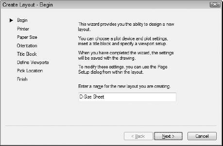
Creating a simple paper space layout is straightforward, thanks to the Create Layout Wizard, as shown in Figure 5-2. (Yes! Finally, a useful AutoCAD wizard.) The command name is LAYOUTWIZARD, and it's missing in action from AutoCAD 2010's new user interface; to get to it, enter LAYOUTWIZARD at the keyboard.
Tip
Although the Create Layout Wizard guides you step by step through the process of creating a paper space layout from scratch, it doesn't eliminate the necessity of coming up with a sensible set of layout parameters. The sheet size and plot scale that you choose provide a certain amount of space for showing your model (see the information earlier in this chapter), and wizards aren't allowed to bend the laws of arithmetic to escape that fact. For example, a map of Australia at a scale of 1 inch = 1 foot won't fit on an 8 1/2- × 11-inch sheet, no way, no how. In other words, garbage in, garbage (lay)out. Fortunately, the Create Layout Wizard lends itself to experimentation, and you can easily delete layouts that don't work.
Follow these steps to create a layout:
Type LAYOUTWIZARD and press Enter.
The Create Layout Wizard displays its first page and prompts you to enter a name for the new layout.
Give the new layout a name and click Next.
In place of the default name, Layout3, I recommend something more descriptive — for example, D-Size Sheet. Or you can call it A1-Size Sheet if you're of the metric persuasion.
Choose a printer or plotter to use when plotting this layout and click Next.
Think of your choice as the default plotter for this layout. You can change to a different plotter later or create page setups that plot the same layout on different plotters. (I explain page setups in Chapter 16.)
Note
Many of the names in the configured plotter list should look familiar because they're your Windows printers (system printers in AutoCAD lingo). Names with a
.pc3extension represent nonsystem printer drivers. See Chapter 16 for details.Choose a paper size, specify whether to use inches or millimeters to represent paper units, and click Next.
The available paper sizes depend on the printer or plotter that you selected in Step 3.
Specify the orientation of the drawing on the paper and click Next.
The icon displaying the letter A on the piece of paper shows you which orientation is which.
On the Create Layout – Title Block page, select None and click Next.
I don't recommend selecting one of the two available title blocks, as the odds are slim that either will fit on the paper size you selected earlier.
Warning
Earlier AutoCAD releases included a handy set of predrawn title blocks for a range of both imperial and metric paper sizes. All but two of them have disappeared, and those two are still the only ones in AutoCAD 2010. Unfortunately, neither of them is likely to work out for you. If in Step 4 you chose inches as your units and any paper size other than ARCH D (36.00 × 24.00 inches), or millimeters as your units and any paper size at all, the title block will not fit the sheet.
Note
When you know your way around the program a bit, you can always draw, insert, or xref a title block later. See Chapters 17 and 18 for information about inserting or xrefing a title block. You can also add custom title block drawings to your AutoCAD Template folder. If you want to know where to put them, see the section on making templates in Chapter 4.
Define the arrangement of viewports that AutoCAD should create and select the viewport scale for them all from the drop-down list. Then click Next.
A viewport is a window from paper space into model space. You must create at least one viewport to display the model in your new layout. I tell you more about viewports later in this chapter.
Tip
The default Viewport scale, Scaled to Fit, ensures that all of your model drawing objects appear in the viewport, but it results in an arbitrary scale factor. Most technical drawings require a specific scale, such as 1:100 or 1/8″ = 1′−0″.
Click Select Location to specify the location of the viewport(s) on the layout; then pick the viewport's corners. When the wizard returns, click Next.
After you click the Select Location button, the Create Layout Wizard displays the preliminary layout with any title block that you've chosen. Pick two points to define a rectangle that falls within the drawing area of your title block (or within the plottable area of the sheet, if you chose no title block in Step 6).
AutoCAD represents the plottable area of the sheet with a dashed rectangle near the edge of the sheet. If you don't select a location for the viewport(s), the Create Layout Wizard creates a viewport that fills the plottable area of the sheet.
Click Finish.
AutoCAD creates the new layout.
Like the other wizards, the Create Layout Wizard is aimed at new users, or old-timers who have somehow overlooked the introduction of paper space layouts. You won't need to run this wizard every time you start a new drawing, but you may well run it once and then save the resulting file as a template for future drawings (see Chapter 4 for more about templates).
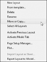
After you create a layout, you can delete, copy, rename, and otherwise manipulate it by clicking Quick View Layouts on the status bar and right-clicking a preview image. If you're using layout tabs rather than buttons, right-click its tab to display the menu or simply drag the tab to a new position. Figure 5-3 shows the right-click menu options in Quick View Layouts.
Note
The From Template option refers to layout templates. After you create layouts in a template (DWT) or a drawing (DWG) file, you can use the From Template option to import these layouts into the current drawing. For details, see the LAYOUT command's Template option in the Command Reference section of online help.
Many drawings require only one paper space layout. If you always plot the same view of the model and always plot to the same device and on the same size paper, a single paper space layout should suffice. If you want to plot your model in different ways (for example, at different scales, with different layers visible, with different areas visible, or with different plotted line characteristics), you may want to create additional paper space layouts.
After you create a paper space layout, you suddenly have two views of the same drawing geometry: the view in your original model space and the new layout's view (perhaps decorated with a handsome title block and other accoutrements of plotting nobility). It's important to realize that both views are of the same geometry. If you change the model geometry on one view, you're changing it everywhere because all layouts display the same model space objects.
When you make a layout current, you can switch the active space between paper space (that is, drawing and zooming on the sheet of paper) and model space (drawing and zooming on the model, inside the viewport) in several ways, including the following:
In the drawing area, double-click inside a viewport boundary to move the crosshairs into model space in that viewport. Alternatively, you can double-click outside all viewports (for example, in the gray area outside the sheet) to move the crosshairs into paper space.
Click the Maximize/Minimize Viewport button on the status bar. (For more information, see Chapter 2.)
Enter MSPACE (the command alias is MS) or PSPACE (PS) at the keyboard.
Click the MODEL/PAPER button on the status bar.
When the crosshairs are in model space, anything you draw or edit changes the model in model space and therefore, through the viewports, on all paper space layouts. When the crosshairs are in paper space, anything you draw appears only on that one layout. It's as though you were drawing on an acetate sheet over the top of that sheet of plotter paper — the model beneath remains unaffected.
This behavior can make your brain hurt until you get used to it. To avoid confusion, stick with the following approach (at least until you're more familiar with paper space):
If you want to edit the model, do so in full-screen model space. Click the Model tab if tabs are displayed, or click the Model button if tabs are hidden. (The Model button is the one with the little black icon; don't confuse it with the MODEL/PAPER button, which switches between model and paper space within the same layout.) Don't try to edit the model in a paper space viewport — it's a very inefficient use of your screen space.
If you want to edit a particular layout without affecting the model, use one of the methods I've described to make that layout current, and make sure that the crosshairs are in paper space.
When you start working in layouts, it may not always be crystal clear whether you're in model space or paper space. The status bar button will help — it will say PAPER if you're in paper space or MODEL if you're in the other place. Here are a few other ways to tell your spaces apart:
Check the crosshairs. If you're in paper space, you can move the crosshairs over the entire drawing area. If you're in model space, you can move the crosshairs only within the currently active viewport; if you try to move the crosshairs outside the viewport, they turn into a Windows selection arrow.
Select some model geometry. Try clicking some objects you know are in model space. If you can select them and they highlight, you're in model space. If nothing happens when you click them, they're inaccessible because you're in paper space.
Check the UCS icon. The UCS icon is that ... er, iconic symbol at the lower-left corner of the drawing area. The model space icon takes the shape of two arrows at right angles to each other, with the arrows pointing away from their intersection. The paper space icon is triangular, and the closed, three-sided shape represents a flat plane. If you don't see such a symbol, click the View tab on the Ribbon, and on the Coordinates panel, click the Show UCS Icon flyout; then choose either Show UCS Icon or Show UCS Icon at Origin, as shown in Figure 5-4.

A viewport is a rectangular paper space object — a window into your drawing sheet — through which you view model space objects from paper space. By default, when you create a new layout, a large single viewport is created.
Note
The viewports I talk about in this chapter are paper space viewports. You can also create viewports in model space, but they're completely different animals. Model space viewports are also known as tiled viewports because they can't have any space between them, like bathroom tiles. You can use tiled viewports to look up close at widely separated areas of your screen. What's potentially confusing is that AutoCAD uses the same command name, and even the same dialog box, for creating the two different types. For this chapter, make sure that you're in paper space when you create layouts.
Paper space viewports are assigned drawing scales, and you can have multiple viewports with different scales on the same layout. For example, one viewport can show the floor plan of an exhibit space at 1/4″ to one foot, and another viewport can show an enlarged view of a display cabinet at 1″=1′. Because the individual viewports are scaled, the entire layout can be plotted at 1:1.
The Create Layout Wizard is fine when you're starting out, but most real drawings have unique, non-standardized arrangements of viewports. When creating layouts, it's often easiest to create viewports from scratch. The following procedure explains how:
Using one of the techniques described in the "Creating a layout" section earlier in this chapter, create a new layout in your drawing.
For example, click Quick View Layouts to display the preview images and then right-click any of the images and choose New Layout. A new layout is added to the end of the image strip.
Click the image for the new layout to open it.
A new layout appears in the drawing window, showing the default sheet area and a single rectangular viewport centered on the sheet. You aren't going to use this viewport.
Move the crosshairs over the viewport boundary and click to select it. Press the Delete key.
Although they don't behave like other drawing objects, viewports are objects, just like lines or circles. And like any other drawing objects, they can be selected and moved, copied, arrayed — or deleted.
On the Ribbon, click the View tab; then, in the Viewports panel, choose New. In the Viewports dialog box, click Single in the list of standard viewports at the left and then click OK.
AutoCAD prompts you to pick the first corner for the new viewport.
Pick a point somewhere on the blank page to locate the first corner of the new viewport.
AutoCAD prompts you to pick the second corner.
Pick another point to place the second corner of the new viewport.
AutoCAD draws the viewport, and the model space geometry appears inside it. Next, specify a drawing scale for your viewport(s).
Specifying the correct viewport scale sooner rather than later bestows a couple of important benefits:
Correctly scaling viewports allows you to use annotative documentation objects, such as text, dimensions, hatch patterns, blocks, and noncontinuous (dash-dot) linetypes. I introduce you to annotative objects in Chapter 13.
Correctly scaling all your viewports allows you to easily plot the completed layout at a scale of 1:1 while retaining individual, true-to-scale viewports.
Double-click inside the viewport you want to apply a scale to.
Model space becomes active, as it must, because that's the space you have to scale. The Viewport Scale button appears toward the right side of the status bar when model space is activated in a layout.
Click the Viewport Scale button on the status bar.
Clicking the Viewport Scale button opens a pop-up list of every drawing scale registered in the scales list — including metric scales even if you're working in an English-units drawing, and vice versa.
Tip
Most of the time, for most people, there are way too many scales in the lists you see in the Viewport Scale button and the Plot dialog box. AutoCAD has a handy dandy Edit Scale List dialog box that lets you remove those imperial scales if you never work in feet and inches and vice versa, if you work only in metric. To run through your scales, choose Scale List from the Annotation Scaling panel on the Annotate tab, or type SCALELISTEDIT and press Enter to open the Edit Scale List dialog box. If you make a mistake, the Reset button in the Edit Scale List dialog box will restore all the default scales.
Find the scale you want to apply to the active viewport and select it from the list.
The display zooms in or out to adjust to the chosen viewport scale.
Warning
Reread that last sentence and then think about how often you have to pan and zoom in your drawing. If you zoom inside a viewport whose scale you've set — kaboom! — you just blew the scale off the map. Luckily, you can prevent yourself or anyone else from inadvertently destroying your beautifully arranged and scaled viewport by completing the final steps of viewport setup:
Make sure you're in paper space (check the UCS icon or move the crosshairs).
Select the boundary of the viewport whose arrangement you want to protect.
If you have Quick Properties turned on at the status bar, a window appears listing the main object properties of the viewport (see Chapter 6 for more about Quick Properties and object properties in general). If Quick Properties is disabled, you can right-click after selecting the viewport.
Select Display Locked and then select Yes.
Locking the display sets AutoCAD up for some nifty zooming ... if you're in paper space, a normal zoom is executed. If you're in model space inside a viewport, a normal zoom would wreck the scale, so when you try to zoom, AutoCAD near-instantaneously switches to paper space, zooms you in, and then switches back to model space. Sheer prestidigitation!
Tip
Sometimes the perfect viewport arrangement requires that a smaller viewport be completely surrounded by a larger one. Easy enough to create, yes, and easy to select — as long as you're in paper space. However, if you're in model space and you want to click from one viewport to the next to make it current, it's impossible to make model space current in a completely surrounded viewport by clicking inside it. Let your fingers come to the rescue: The Ctrl+R key combination cycles through model space in all drawing viewports, even if they're completely surrounded by other viewports.
And there you have your 12-step program to layout bliss! All that setup had a purpose, of course: to enable you to print perfect paper plots (or plot perfect paper prints. if you prefer to see it that way). I cover plotting in depth in Chapter 16, but a short introductory word here might be useful.
Note
What happens when you want to rotate a viewport? Perhaps you're drawing an elevator shaft, and the view would fit better on the sheet lengthwise than in its "correct" vertical orientation. A logical person might think that rotating a viewport, say, 90° would rotate the view as well. Until now, AutoCAD hasn't worked like that; you might rotate the viewport object, but the contents remained firmly fixed in model space. AutoCAD 2010 introduces a welcome enhancement to viewports: You can now rotate the displayed viewport content and the viewport itself:
As this chapter describes, you can use AutoCAD's paper space feature to compose one or more layouts for plotting your drawing in particular ways. Each layout lives on a separate tab, which you click at the bottom of the drawing area — or in a secret hiding place if you've hidden the Model and Layout tabs. AutoCAD saves plot settings (plot device, paper size, plot scale, and so on) separately for each of the layouts as well as model space.
Whether to plot model space or a layout in a drawing depends entirely on how the drawing was set up. If you or someone else went through a layout setup procedure similar to the one in this chapter, you probably should plot the layout. If not, plot model space.
Warning
Viewport boundaries will print if you don't pay attention to where you create them. What that means is that each drawing view has a nice rectangular border around it. Nice, but a definite no-no in every drafting office. In Chapter 6, I introduce you to object properties, including probably the most important one, layers. You can define a layer so that objects on it do not plot, and that's where you should create your viewports.
One thing that might tip the scales in favor of hiding the layout tabs and going with status bar buttons is the teensy bit of drawing space along the bottom of the drawing area you can regain by turning off the layout tabs. Just right-click the Model tab or a layout tab and select Hide Layout and Model Tabs. The tabs vanish, and the Model and Layout buttons appear on the status bar. To put things back the way they were, right-click one of the new status bar buttons and choose Display Layout and Model Tabs.
Tip
If you don't have any paper space drawings handy, you can use one of the AutoCAD sample drawings. Refer to the New in AutoCAD 2010 paragraph in the "Setting Up a Layout in Paper Space" section earlier in the chapter.
Tip
Some different ways of plotting the same model can be handled in a single paper space layout with different page setups. See Chapter 16 for more details. If your projects require lots of drawings, you can parlay layouts into sheet sets — a feature that makes for more sophisticated creation, management, plotting, and electronic transfer of multisheet drawing sets. (Sorry, LT users — AutoCAD LT doesn't support sheet sets.) Again, see Chapter 16 for more information.