
1
Analysis of Six-Phase Grid Connected Synchronous Generator in Wind Power Generation
Arif Iqbal1* and Girish Kumar Singh2
1Department of Electrical Engineering, Rajkiya Engineering College Ambedkar Nagar, Akbarpur, India
2Department of Electrical Engineering, Indian Institute of Technology Roorkee, Roorkee, India
Abstract
Owing to meet the incremental need of energy with exhaustion of fossil fuel in few upcoming years, renewable power generation has emerged as a potential and permanent solution in present scenario. In this regard, research has diverted toward exploration and development of various new techniques of renewable power generation for last few decades, and various systems have been adopted in both isolated and grid connected modes. Among various available options (solar, wind, biomass, tidal, etc.), the wind power generation system has a major market share due to its pollution-free operation together with its economic viability and mature technology. Presently, wind power generation system is increasing exponentially, particularly in on-shore sites of India and European subcontinents. Wind power generation system works on a successful operation and coordination of various parts, where an electric generator is an important component. Hence, the selection of suitable electrical machine (as generator) is of paramount importance for reliable operation of complete wind power generation system. Conventionally, three-phase electrical machine is employed. But, in last two decades, the multiphase (more than three-phase) machine is replacing the conventional one. This is because of various inherent potential advantageous features present in multiphase machines, when compared with its three-phase equivalent. This includes the elimination of lower order space, resulting in lower torque pulsation, enhanced power handling capability in the same frame (approximately 175%), and higher degree of freedom with improved reliability. Hence, multiphase machines have to be explored and investigated in various operational aspects for power generation. In this chapter, a six-phase synchronous machine is selected as a potential option as generator in grid connected mode for wind power generation system. An exhaustive dynamic analysis has been presented during various working conditions. Moreover, generator has been further investigated under steady state with the inclusion of small disturbance (i.e., small signal stability) through linearized model using dq0 approach. Linearized model was used to determine the absolute stability using eigenvalue criteria wherein, the effect of parametric variation is presented, related with both stator and rotor side. It was noted that the stability of generator operation can be enhanced with increased values of stator resistance. On rotor side, with higher value of leakage reactance of field winding circuit and/or by increased resistance of damper winding along q axis.
Keywords: Wind power generation, six-phase synchronous generator, small-signal stability, dynamic analysis
1.1 Introduction
The development of human civilization resulted in a tremendous demand of electrical power with a fear of fossil fuel exhaustion within a few years. This has diverted the researcher’s attention to explore and develop the renewable resources for power generation as a potential and permanent solution in present scenario. Motivation toward the development of different types of renewable power generation (like solar, wind, biomass, and tidal) is also due to the presence of various attractive advantages, particularly pollution-free operation, free availability with economic viability, and advanced technology [1, 2]. Among the various developed options, wind power generation has been adopted worldwide and exhibits a major market share in the field of renewable resources. Presently, wind power generation system is increasing exponentially, particularly in on-shore sites of India and European subcontinents. According to report updated on Global Wind Energy Council (GWEC) [3], power extraction is drastically increased by 52 GW and 60 GW by 2017 and 2020, respectively, and expected to reach a total of 840 GW by 2022.
Wind power generation system works on a successful operation and coordination of various parts, where an electric generator is an important component. Hence, the selection of suitable electrical machine (as generator) is of paramount importance for reliable operation of wind power generation system. Conventionally, three-phase electrical machine (mostly synchronous machine) is employed. But, in last two decades, the multiphase (more than three-phase) machine is replacing the conventional one. This is because of the presence of various potential advantages when compared with its three-phase equivalent. This includes the elimination of lower order space harmonics, resulting in lower torque pulsation, higher power handling capability in the same frame (approximately 175%), and higher degree of freedom with improved reliability [4]. This signifies the technical and economic suitability of using multiphase machine when compared with its three-phase equivalent. Hence, an enhanced use of multiphase drives have been reported in different high power applications, not limited to ship propulsion, electric traction, more-electric aircraft, thermal and nuclear power plant, and battery and hybrid electric vehicles. Research in this field is tremendously going on, particularly from electric power generation point of view. Available literatures are showing a general feasibility of multiphase system [4, 5]. On generation side, the concept of multiphase (more than three-phase) machine was initially originated in late 1920s when larger power generation got hampered due to the limitations in circuit breaker interrupting capability. To overcome this situation, attention of scientists was diverted to the machine having double windings embedded in its stator [6]. It was after this time that research continued in the field of multiphase machine with steady, but in slower way. Utilization of multiphase synchronous generator was used in 1980 [7] for power generation in electric railway coaches. A few mathematical analysis of alternator with two three-phase winding was carried out by using orthogonal transformation for the elimination of time-dependent coefficient from system differential equations [8]. Six-phase synchronous generator in conjugation with three-to six-phase conversion transformer was analyzed for harmonic content [9]. In six-phase synchronous machine, mutual coupling effect between two sets of balanced three-phase stator winding is considered in [10], and under steady-state ac-dc stator connection [11] has been also presented and analyzed by using average-value modeling with line commutated converter [12]. A detailed mathematical modeling of six-phase synchronous generator using Park’s variable has been carried out in [13] under different working conditions at stand-alone mode, where an enhanced power handling capability by 173% was achieved when compared with its three-phase equivalent. A detailed experimental investigation of six-phase synchronous generator in stand-alone mode was carried out for renewable power generation in conjugation with hydropower plant [14]. Considering the suitability in generating mode, this chapter presents a mathematical modeling of grid connected six-phase synchronous generator applicable for wind power generating system, followed by the dynamic response under load variation.
Being an integral component in wind power generation, an operational stability of six-phase synchronous generator under steady state (i.e., small signal stability) is also of prime importance. Although, the small-signal stability analysis of three-phase synchronous machine is available in few available literature [15] using root locus [16] and Nyquist criteria [17]. But, for multiphase (i.e., six-phase) synchronous machine, a very limited literature is available for small-signal stability analysis. An introductory analysis of synchronous machine was reported in [18] followed by the determination of stability limits under parametric variation and different working conditions [19] when compared with its three-phase counterpart [20]. With the aim to access the suitability and applicability in wind power generating system, this chapter is dedicated to present a small-signal stability analysis of grid connected six-phase synchronous generator showing a comparison with its three-phase equivalent. For this purpose, a linearized version of six-phase synchronous generator model has been derived and used to evaluate the system eigenvalue. Eigenvalue criteria are used for small signal stability analysis under different machine parametric variation. A comparative analysis, from stability view point, is also presented using Park’s (dq0) variable for both grid connected three- and six-phase synchronous generator.
1.2 Analytical Modeling of Six-Phase Synchronous Machine
To design a six-phase machine, it is a common strategy to split the stator winding into two through phase belt splitting namely, abc and xyz having the angular displacement of α = 30°, to have asymmetrical winding [4, 18, 19]. Rotor of the machine remains same having the field winding fr and damper windings kd and kq along d-q axes, respectively. While going onward for the mathematical modeling, some of the important simplifying assumptions are considered [21, 22]:
- Both the three-phase stator windings (abc and xyz) are symmetrical balanced having a perfectly sinusoidal distribution in the air-gap.
- Flux and mmfs are sinusoidal with no space harmonics.
- Saturation and hysteresis effects are ignored.
- No skin effect, i.e., winding resistance, is not dependent on frequency.
Although, voltage and electromagnetic torque can be mathematically expressed in terms machine variables, which results in non-linear differential equations [22]. The non-linearity is due to the time varying inductance term. For simplicity, with constant inductance terms, concept of reference frame theory is used, and equations are preferably written in rotor reference frame using Park’s equation. Mathematically, voltages and flux linkage per second of a six-phase synchronous machine using Park’s variables are as follows [21–23]:
1.2.1 Voltage Equation


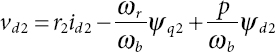
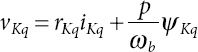

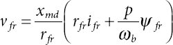
where p shows the differentiation function w.r.t. time.
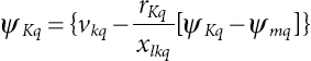
1.2.2 Equations of Flux Linkage Per Second
where
The parameters of rotor circuit are referred to the stator winding set abc. These voltage and flux linkage equations suggest the equivalent circuit, as shown in Figure 1.1, wherein Llm and Lldq represent leakage inductance of common mutual and cross mutual coupling between d and q-axis of stator circuit, respectively:
where xlax, xlay, and xlaz indicate leakage reactance between phase a (of winding set abc) with each phase of other winding set xyz.
Phenomenon of mutual coupling is due to the sharing of same slot by stator winding conductor of different phase. This is signified by the term of common mutual leakage reactance (xlm). Value of xlm is dependent on displacement angle (α) and winding pitch, resulting in the variation in harmonic coupling of windings. By neglecting xlm, some variation is noted in the voltage harmonic distortion [13] with no change in transient effect. A detailed procedure for the determination of slot reactance is available [24] together with the standard method to evaluate the machine parameters [25, 26].
Detailed mathematical simulation of six-phase synchronous machine is based on determination of voltage and torque equations in integral form with flux linkage per second and speed as state variable, winding currents as output, connected grid voltage and prime mover torque as input variables. The voltage equations (1.1) to (1.7) together with the flux linkages equations (1.8) to (1.14) are firstly solved for the currents, which are then substituted in the voltage equations. Integral forms of mathematical equations are as follows:

Figure 1.1 Equivalent circuit representation of a six-phase synchronous machine.


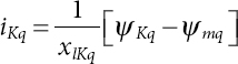
Current in terms of flux is written as follows:


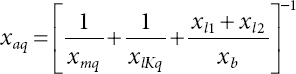
ψmq and ψmd are defined using state variables as follows:


where

Developed electromagnetic torque (Te) and rotor dynamic equations for the machine can be expressed as follows:
where
the developed torque associated with the first winding set abc, and

the developed torque associated with the second winding set xyz.

where Te is overall developed electromagnetic torque and Tl is the prime mover torque. In the mathematical modeling, both motoring and generating mode is possible. In this chapter, generating mode is considered, where mechanical input torque Tl is fed from prime mover to generate the electrical output power, resulting the flow of current from machine to connected utility grid.
Input voltages vabcs and vxyzs in stationary frame coordinate are transformed directly to ![]() in rotor reference frame by using the transformation matrix [20, 22]
in rotor reference frame by using the transformation matrix [20, 22] ![]() associated with each winding sets abc and xyz, respectively. The voltages applied to the damper windings are not shown, because voltages are zero due to short-circuited windings.
associated with each winding sets abc and xyz, respectively. The voltages applied to the damper windings are not shown, because voltages are zero due to short-circuited windings.
1.3 Linearization of Machine Equations for Stability Analysis
In above section, current and flux linkage per second are both related to each other [Equation (1.26) to (1.32)], one variable vector (current or flux linkage per second) can be taken as state variable. The choice of state variable is generally determined by the application [15]. Here, current is selected as state variable (i.e., independent variable). Hence, the voltage-current relation of machine in matrix form is expressed as follows:
where
[v] = [vq1, vd1, vq2, vd2, vKq, vfr, vKd]T
[i] = [iq1, id1, iq2, id2, iKq, ifr, iKd]T
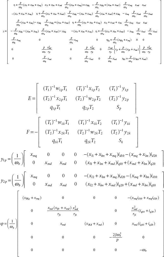
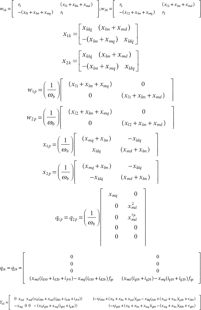
[z] is the impedance matrix defined in the Appendix.
Using the concept of Taylor series expansion, the linearization of machine equations (1.40), (1.41), (1.42), and (1.43) results in a set of equations, which are expressed in matrix form:
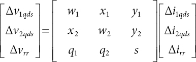
where matrix elements are explained in the Appendix.
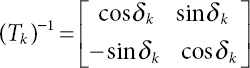
Grid voltage with constant magnitude and frequency is presented in synchronous reference frame. Hence, it is advantageous to relate the variables in synchronously rotating reference frame (i.e., and ![]() to rotor reference frame (i.e.,
to rotor reference frame (i.e., ![]() and is given by Equation (1.45).
and is given by Equation (1.45).
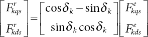

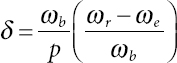
whereas β shows the phase difference between the terminal voltage of phases a and x. Numerically, the numerical value of both α and β is 30° electrical.
The linearized version of above of nonlinear differential equation (1.45) with suitable approximation (cosΔδk = 1 and sinΔδk = Δδk) results in
Inverse transformation of above equation yields
where Fr and Fe represent the d-q performances indices under steady state.

Substituting Equations (1.46) and (1.47) into Equation (1.44) results in

and is rearranged as
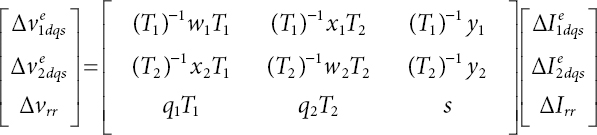
Simplified version of above equation can be written as
In above expressions, the additional subscript “0” ![]() represent the value during steady state. Rewriting Equation (1.52) in fundamental form
represent the value during steady state. Rewriting Equation (1.52) in fundamental form
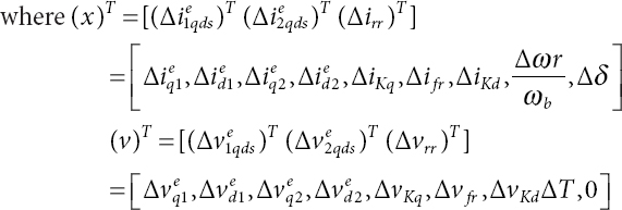
where

In above linearized model of machine, the effect of mutual coupling between stator winding sets abc and xyz is considered (by using mutual leakage reactance, xlm and xldq). Results are presented in consideration of the asymmetrical six-phase synchronous machine (α = 30° electrical) in comparison with its three-phase equivalent.
1.4 Dynamic Performance Results
Dynamic analysis of any electrical system is of prime importance to understand its operating characteristic under different conditions changing suddenly. Therefore, the mathematical model developed in previous section has been effectively used to analyze the behavior of grid connected six-phase synchronous generator under sudden change in active load. For this purpose, a set of differential equations that describe the synchronous machine operation were simulated in MATLAB/Simulink environment. Simulation has been carried out for a machine of 3.2 kW, 6 poles, whose parameters are mentioned in the Appendix.
Computer traces in Figures 1.2 and 1.3 are showing the dynamic behavior of six-phase synchronous generator due to a step change in output active power from 0% to 50% of rated/base value at time t = 5 s and further increase in output power by 50% (i.e., at full load) at time t = 15 s. It is assumed that the terminal voltage and frequency is constant irrespective of the change in load torque. Input phase voltage was maintained constant at 240 V, 50 Hz, operating at 0.85 power factor (lagging). Initially, generator is operating at no load condition at synchronous speed. At time t = 5 s, a step increase in output power, and hence, increase in prime mover applied torque Tl is considered. This resulted in the increase in rotor speed immediately, following the step increase in prime mover torque as shown in Figure 1.2a, where the load angle δ increases in Figure 1.2c. The rotor speed continues to increase till the accelerating torque on the rotor vanishes. It can be noted from Figure 1.2b that the speed increases to approximately 105 rad/sec at the time when Te equal to Tl. At this time, accelerating torque is zero and the rotor is running above synchronous speed; hence, load angle δ, and thus motor torque Te will keep on decreasing. Decrease in torque Te results in decrease in output power of the machine that causes the rotor to decelerate toward synchronous speed. Hence, due to rotor inertia, it will continue to decelerate below synchronous speed, and consequently, load angle δ begins to increase, with increase in generated torque Te. In this way, damped oscillation of machine continues and settles to a new-steady state value.

Figure 1.2 Dynamic response of motor following the change in load torque showing (a) motor torque Te, (b) rotor speed ωr, and (c) load angle, delta.
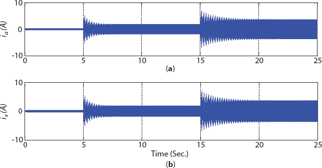
Figure 1.3 Dynamic response of motor following the change in load torque showing stator currents (a) ia and (b) ix.

Figure 1.4 d-q component of stator winding currents (a) Iq1, (b) Id1, (c) Iq2, and (d) Id2.
Due to the increase in generator prime mover input torque, increase in stator phase current can be noted in Figure 1.3, which is required to meet the increased output. The increase in stator current is associated with the increase in active output power of the generator, while maintaining its operation at constant power factor (i.e., constant reactive power). Hence, the change in q-axis component of stator current (active component of current changes from 1.8 A at 50% output power to 3.6 A at rated output, approximately) is depicted in Figure 1.4, with no change in its d-axis component of stator current (reactive component of current), of both the winding sets abc and xyz.
1.5 Stability Analysis Results
For small signal stability analysis, eigenvalue is calculated from system characteristic equation:
where unknown root λ is calculated (i.e., eigenvalue) with A and I as system matrix and identity matrix, respectively. For a system to be stable, all the real and/or real component of eigenvalues must be negative [15, 18–20].
State equation (1.53) and equation 8.3-45 of reference [15] are using nine and seven state variables, respectively. Hence, nine and seven eigenvalues will be obtained for six and three-phase generator, respectively. In six-phase generator, out of nine evaluated eigenvalues, three eigenvalues are complex conjugate pairs and the remaining are real. Evaluated eigenvalue of six-phase and three-phase generator is given in Tables 1.1 and 1.2, respectively. Eigenvalue was evaluated by considering the same flux level in both three- and six-phase machine. This was ensured by considering the stator voltage of three-phase machine as twice of six-phase machine [27]. Hence, value of the terminal voltage for three-phase and six-phase machine was taken as 240 and 120 V, respectively. Results are given for both machine considering the same load at 50% of rated value, at power factor 0.85 (lagging). It is worthwhile to mention here that it is a difficult to establish a correlation of eigenvalue with machine parameter [15]. It has been considered by changing a machine parameter, keeping other at nominal value and noting the variation in eigenvalue [18].
Table 1.1 Eigenvalues of six-phase synchronous generator.
| Nomenclature | Eigenvalues |
| Stator eigenvalue I | −107.8 ± j104.7 |
| Stator eigenvalue II | −19.2 ± j110.3 |
| Rotor eigenvalue | −5.1 ± j38.2 |
| Real eigenvalue | −9136.3, −703.5, −21.0 |
Table 1.2 Eigenvalues of three-phase synchronous generator.
| Nomenclature | Eigenvalues |
| Stator eigenvalue | −38.3 ± j103.2 |
| Rotor eigenvalue | −27.9 ± j50.4 |
| Real eigenvalue | −8719.7, −503.3, −10.7 |
In Equation (1.53), derivative component (i.e., with its elements with subscript p) is indicated by coefficient matrix E, with remaining terms (i.e., subscript k) of linearized machine equations are shown by the coefficient matrix F. Matrices E and F elements are defined in the Appendix.
1.5.1 Parametric Variation of Stator
During the analysis, it was assumed that the two sets of stator winding, say, abc and xyz, are identical. Hence, value of resistance and winding leakage inductance will be same (i.e., ![]() It may be noted that in figures of the following sections, dark and dash line indicate the real and imaginary component of eigenvalue, respectively.
It may be noted that in figures of the following sections, dark and dash line indicate the real and imaginary component of eigenvalue, respectively.
With increase in stator resistance, generator operation tends toward stability from both stator and rotor side due to higher magnitude of negative real component of eigenvalue, as shown in Figure 1.5a for three-phase generator and Figures 1.6a and b for six-phase generator. Real eigenvalue I and II was found to be decreased as shown in Figures 1.5b and c for three-phase generator, and in Figures 1.6c and d for six-phase generator. But a slight increase in real eigenvalue III of three-phase generator with no change was noted in six-phase generator as shown in Figures 1.5d and 1.6e, respectively.
With the increase in stator leakage reactance, a trend of eigenvalue variation was found to be reversed. On stator side, real component of eigenvalue was increased by 31.5% (shown in Figure 1.7a) for three-phase generator, and by 50% and 19.8% in stator eigenvalue I and II for six-phase generator, as shown in Figure 1.8a. However, a slight increase in real component of rotor eigenvalue for three-phase generator was noted, shifting the operation toward instability. But, in six-phase generator, increased magnitude of real component of rotor eigenvalue (shown in Figure 1.8b), signifying the tendency of stable operation. The remaining three eigenvalues remain negative with small variation as shown in Figures 1.7b–d and Figures 1.8c–e for three- and six-phase generator, respectively. It may be noted that the magnitude (with negative sign) real eigenvalues of six-phase generator remain higher (in magnitude); and hence, is more stable when compared with three-phase generator.
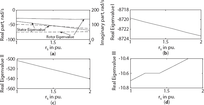
Figure 1.5 Variation in eigenvalue of three-phase synchronous machine with stator resistance change (a) stator and rotor eigenvalue, (b) real eigenvalue I, (c) real eigenvalue II, (d) real eigenvalue III.

Figure 1.6 Variation in eigenvalue of six-phase synchronous machine with stator resistance change (a) stator eigenvalue I and II, (b) rotor eigenvalue, (c) real eigenvalue I, (d) real eigenvalue II, (e) real eigenvalue III.
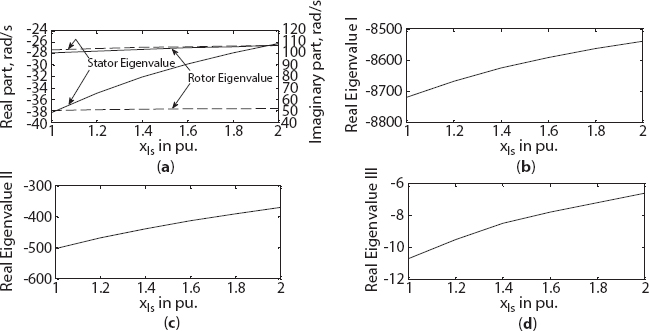
Figure 1.7 Variation in eigenvalue of three-phase synchronous machine with stator leakage reactance change (a) stator and rotor eigenvalue, (b) real eigenvalue I, (c) real eigenvalue II, (d) real eigenvalue III.

Figure 1.8 Variation in eigenvalue of six-phase synchronous machine with stator leakage reactance change (a) stator eigenvalue I and II, (b) rotor eigenvalue, (c) real eigenvalue I, (d) real eigenvalue II, (e) real eigenvalue III.
1.5.2 Parametric Variation of Field Circuit
In this section, the effect of variation in field circuit parameter (resistance rfr and leakage reactance xlfr) is presented for both three- and six-phase generator. With the increase in field circuit resistance, variation in real component of stator eigenvalue was not observed in case of three-phase generator, as shown in Figure 1.9a. But, stator eigenvalue I was increased by 50%, showing the tendency of instability as shown in Figure 1.10b. But on rotor side, operation tends toward stability as shown in Figure 1.10b. A small increase in the value of real component of rotor eigenvalue was noted in three-phase generator, as shown in Figure 1.9a. Real eigenvalue I and III is decreased for three-phase generator as shown in Figures 1.9b and d, respectively, with no variation in real eigenvalue II as shown Figure 1.9c. On the other hand, trend of variation in real component of eigenvalue was found to be different for six-phase generator. All the real eigenvalue I, II, and III was found to be decreasing (in magnitude with negative sign) as shown in Figures 1.10c, d, and e, respectively. It may be noted here that the larger variation was in the smallest real eigenvalue III with no or smaller change in other real eigenvalues. This is because, on rotor, field circuit has largest time constant giving rise to smallest eigenvalue III [15, 18].

Figure 1.9 Variation in eigenvalue of three-phase synchronous machine with field circuit resistance change (a) stator and rotor eigenvalue, (b) real eigenvalue I, (c) real eigenvalue II, (d) real eigenvalue III.

Figure 1.10 Variation in eigenvalue of six-phase synchronous machine with field circuit resistance change (a) stator eigenvalue I and II, (b) rotor eigenvalue, (c) real eigenvalue I (d) real eigenvalue II, (e) real eigenvalue III.
With the increase in field leakage reactance xlfr, magnitude of real component of stator eigenvalue was decreased for both three- and six-phase generator, as shown in Figures 1.11a and 1.12a, respectively. But, a small variation in real component of rotor eigenvalue was noted for both three- and six-phase generator, as shown in Figures 1.11a and 1.12b, respectively. A small linear or no change was noted in eigenvalue I and II for both three- and six-phase generator, as shown in Figures 1.11b and c and Figures 1.12c and d, respectively. But, a larger variation in real eigenvalue III was noted for both three- and six-phase generator, as shown in Figures 1.11d and 1.12e, respectively.

Figure 1.11 Variation in eigenvalue of three-phase synchronous machine with field circuit leakage reactance change (a) stator and rotor eigenvalue, (b) real eigenvalue I, (c) real eigenvalue II, (d) real eigenvalue III.

Figure 1.12 Variation in eigenvalue of six-phase synchronous machine with field circuit leakage reactance change (a) stator eigenvalue I and II, (b) rotor eigenvalue, (c) real eigenvalue I, (d) real eigenvalue II, (e) real eigenvalue III.
1.5.3 Parametric Variation of Damper Winding, Kd
In this section, parameter variation of damper winding along d-axis Kd (i.e., resistance rKd and leakage reactance xlKd) is considered in the evaluation of generator eigenvalues. With the increase in resistance rKd, both the stator and rotor eigenvalues were found to be unchanged for three-phase generator, as shown in Figure 1.13a. However, some change was found in stator eigenvalue I and rotor eigenvalue for six-phase generator, as shown in Figures 1.14a and b, respectively. A pronounced increase in the magnitude of real eigenvalue I was found for both three- and six-phase generator, as shown in Figures 1.13b and 1.14c, respectively. But no change in eigenvalue II and III was found for three-phase generator with small variation for six-phase generator, as shown in Figures 1.13c and d and Figures 1.14d and e, respectively.
With the increased value of leakage reactance xlKd, a major variation was only noted on real eigenvalue I for both three- and six-phase generator as shown in Figures 1.15b and 1.16c, respectively. A slight variation in real eigenvalue III was noted for both three- and six-phase generator as shown in Figures 1.15d and 1.16e, respectively. On stator side, a small variation in real component of eigenvalue was noted (with decrease in real component of stator eigenvalue I for six-phase generator) both three- and six-phase generator as shown in Figures 1.15a and 1.16a, respectively. Real component of rotor eigenvalue was noted to have no/small variation for both three- and six-phase generator as shown in Figures 1.15a and 1.16b, respectively.

Figure 1.13 Variation in eigenvalue of three-phase synchronous machine with damper resistance change along d-axis (a) stator and rotor eigenvalue, (b) real eigenvalue I, (c) real eigenvalue II, (d) real eigenvalue III.

Figure 1.14 Variation in eigenvalue of six-phase synchronous machine with damper resistance change along d-axis (a) stator eigenvalue I and II, (b) rotor eigenvalue, (c) real eigenvalue I, (d) real eigenvalue II (e) real eigenvalue III.

Figure 1.15 Variation in eigenvalue of three-phase synchronous machine with damper leakage reactance change along d-axis (a) stator and rotor eigenvalue, (b) real eigenvalue I, (c) real eigenvalue II, (d) real eigenvalue III.

Figure 1.16 Variation in eigenvalue of six-phase synchronous machine with damper leakage reactance change along d-axis (a) stator eigenvalue I and II, (b) rotor eigenvalue (c) real eigenvalue I, (d) real eigenvalue II, (e) real eigenvalue III.
1.5.4 Parametric Variation of Damper Winding, Kq
With the increase in damper winding resistance rKq, small variation was noted on real component of stator eigenvalue in three-phase generator. But in six-phase generator, it was increased by 50% in stator eigenvalue I (and slight increase in stator eigenvalue II), as shown in Figures 1.17a and 1.18a, respectively. On rotor side, real part of eigenvalue was increased by 46.2% and 49% for both three- and six-phase generator, as shown in Figures 1.17a and 1.18b, respectively. A major effect was found on real eigenvalue II which was decreased by 112% and 82.2% for three-phase and six-phase generator as shown in Figures 1.17c and 1.18d, respectively. In three-phase generator, no change was noted in eigenvalue I and III as shown in Figures 1.17b and d, respectively. But in case of six-phase generator, slight variation was found in real eigenvalue I and III, as shown in Figures 1.18c and e, respectively. During the analysis, it was noted that the effect of variation in the value of reactance xlKq was only found in real eigenvalue II, with no variation on other eigenvalues, hence not shown. Value of real eigenvalue II was increased by 45.7% and 48.2% for three- and six-phase generator as shown in Figures 1.19a and b, respectively.
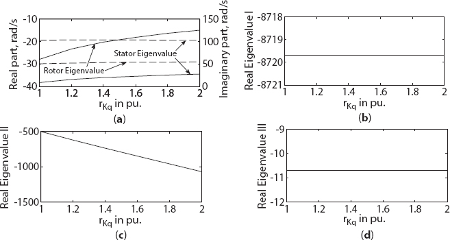
Figure 1.17 Variation in eigenvalue of three-phase synchronous machine with damper resistance change along q-axis (a) stator and rotor eigenvalue, (b) real eigenvalue I, (c) real eigenvalue II, (d) real eigenvalue III.
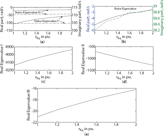
Figure 1.18 Variation in eigenvalue of six-phase synchronous machine with damper resistance change along q-axis (a) stator eigenvalue I and II, (b) rotor eigenvalue, (c) real eigenvalue I, (d) real eigenvalue II, (e) real eigenvalue III.
1.5.5 Magnetizing Reactance Variation Along q-axis
With the increase in magnetizing reactance xmq along q-axis, real part of stator eigenvalue of three- and six-phase generator was decreased by 34.4% and 68.8% (with no variation in stator eigenvalue I), as shown in Figures 1.20a and 1.21a, respectively. A major effect was noted from rotor side. Value of real part of rotor eigenvalue is increasing linearly for both three-phase and six-phase generator. It may be noted that the generator operation becomes unstable at higher value of xmq due to positive value of real part of rotor eigenvalue, as shown in Figure 1.21b. Hence, six-phase generator is more sensitive toward the variation of magnetizing reactance xmq. Also, a linear increase in the value of real eigenvalue II was noted for both three- and six-phase generator as shown in Figures 1.20c and 1.21d, respectively. But in three-phase generator, a higher decrease in real eigenvalue III was found in comparison with six-phase generator as shown in Figures 1.20d and 1.21e, respectively. No variation in real eigenvalue I was found for both three- and six-phase generator, as shown in Figures 1.20b and 1.21c, respectively.

Figure 1.19 Variation in eigenvalue II with damper leakage reactance change along q-axis in (a) three-phase and (b) six-phase generator.

Figure 1.20 Variation in eigenvalue of three-phase synchronous machine with magnetizing reactance change along q-axis (a) stator and rotor eigenvalue, (b) real eigenvalue I, (c) real eigenvalue II, (d) real eigenvalue III.
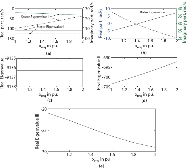
Figure 1.21 Variation in eigenvalue of six-phase synchronous machine with magnetizing reactance change along q-axis (a) stator eigenvalue I and II, (b) rotor eigenvalue, (c) real eigenvalue I, (d) real eigenvalue II, (e) real eigenvalue III.
Both three- and six-phase generator evaluated eigenvalues were found to unchanged with the variation in magnetizing reactance xmd along d-axis. Hence, it is not presented.
1.5.6 Variation in Load
Considering the constant grid voltage at 240 V (rms value per phase), eigenvalue of both three- and six-phase generator is plotted in Figure 1.18 for increase in load from 0.25 to 1.0 pu. From stator side, real component of stator eigenvalue decreases (increase in magnitude with negative sign) for both three- and six-phase generator, as shown in Figure 1.22a. (No variation was noted in stator eigenvalue I, hence not shown). Decrease in the value of real part of stator eigenvalue was higher (70.8%) than its three-phase counterpart (47.9%). Hence, tendency toward stability of six-phase generator is higher than three-phase generator. On rotor side, increase (i.e., decrease in magnitude with negative sign) in real component was noted to be same (20.7%) for both three- and six-phase generator as shown in Figure 1.22b. Hence, under load variation, rotor behavior will be the same for both three- and six-phase generator. On real eigenvalue II, a slight increase in the value for three-phase (by 4.5%) and six-phase generator (by 1.5%) was noted, as shown in Figure 1.22c. Also, a very small decrease in real eigenvalue III for six-phase (by 3.2%) was noted with 17.1% variation in three-phase generator as shown in Figure 1.22d. Hence, both rotor and damper winding behavior will be approximately the same for both three- and six-phase generator. Since, variation in real eigenvalue I was not noted, and hence not shown.

Figure 1.22 Change in real/real component of generator eigenvalue due to load variation. (a) stator eigenvalue, (b) rotor eigenvalue, (c) real eigenvalue II, (d) real eigenvalue III.
1.6 Conclusions
This chapter deals with a detailed analysis of six-phase synchronous generator, applicable for wind power generation system. This includes the mathematical modeling of grid connected six-phase synchronous generator and its dynamic performance under load variation. Initially, machine was operated at no-load followed by the step increase in output power (i.e., active power increased at time t = 5 and 15 s from no-load to 50% of rated, to rated value). Hence, increase in active component (i.e., q-axis component) of current was noted to be increased with no change in reactive component (i.e., d-axis component) current, associated with both the three-phase stator winding. This has resulted in an overall increase in current of both stator winding sets. On the basis of performance results, it may be inferred that a stable operation is achieved with a step change in output power for a grid connected six-phase synchronous generator.
Furthermore, a detailed small signal stability analysis was presented for grid connected six-phase synchronous generator with its three-phase counterpart. For this purpose, a linearized mathematical model was developed using Park’s variables, where eigenvalue criteria were used to access the stability under small disturbance. A larger effect was found with the change in stator resistance on both six-phase and three-phase generator. Six-phase generator was found to be more stable due to larger magnitude of negative component of both stator and rotor eigenvalues. Variation of stator leakage reactance also affects the machine stability. It was found that from rotor side, six-phase generator operation is tending toward stability, while three-phase generator is approaching toward instability. Hence, machine operation will remain more stable under stator leakage reactance variation in comparison with three-phase generator. On the field side, major effect was noted in smallest real eigenvalue III, where under variation in resistance rfr and leakage reactance xlfr, wherein six-phase generator remains stable with respect to its three-phase counterpart. From damper side also, operation of six-phase generator was found to have higher stability when compared with its three-phase equivalent.
Hence, stability of generator operation can be enhanced with increased values of stator resistance and, on rotor side, with higher leakage reactance value of field winding circuit or/and by increased damper winding resistance along q axis.
References
1. Singh, G.K., Self-excited induction generator research—a survey. Electr. Power Syst. Res., 69, 2, 107–114, 2004.
2. Chinmaya, K.A. and Singh, G.K., Performance evaluation of multiphase induction generator in stand-alone and grid connected wind energy conversion system. IET Renewable Power Gener., 12, 7, 823–83, 2018.
3. https://gwec.net/global-figures/wind-energy-global-status
4. Singh, G.K., Multi-phase induction machine drive research survey. Electr. Power Syst. Res., 61, 2, 139–147, 2002.
5. Levi, E., Multiphase electric machines for variable speed applications. IEEE Trans. Ind. Electron., 55, 5, 1893–909, 2008.
6. Alger, P.L., Freiburghouse, E.H., Chase, D.D., Double windings for turbine alternators. AIEE Tans., 49, 1, 226–244, 1930.
7. Kataoka, T. and Watanebe, E.H., Steady-state characteristic of a current-source inverter/double-wound synchronous machine system for AC power supply. IEEE Trans. Ind. Appl., 16, 2, 262–270, 1980.
8. Fuchs, E.F. and Rosenberg, L.T., Analysis of an alternator with two displaced stator windings. IEEE Trans. Power Appar. Syst., 93, 6, 1776–1786, 1973.
9. Hanna, R.A. and Macdonald, D.C., The six-phase generator and transformer into a three-phase power system. IEEE Trans. Power Appar. Syst., 102, 8, 2600–2607, 1983.
10. Schiferl, R.F. and Ong, C.M., Six-phase synchronous machine with ac and dc stator connections, Part I: equivalent circuit representation and steady-state analysis. IEEE Trans. Power Appar. Syst., 102, 8, 2685–2693, 1983.
11. Schiferl, R.F. and Ong, C.M., Six-phase synchronous machine with ac and dc stator connections, Part II: harmonic studies and a proposed uninterruptible power supply schemes. IEEE Trans. Power Appar. Syst., 102, 8, 2694–701, 1983.
12. Sudhoff, S.D. and Wasynczuk, O., Analysis and average value modeling of line commutated converter-synchronous machine systems. IEEE Trans. Energy Convers., 8, 1, 92–99, 1993.
13. Singh, G.K., Modeling and analysis of six-phase synchronous generator for stand-alone renewable energy generation. Energy, 36, 9, 5621–5631, 2011.
14. Singh, G.K., A six-phase synchronous generator for stand-alone renewable energy generation: experimental analysis. Energy, 36, 3, 1768–1775, 2011.
15. Krause, P.C., Wasynczuk, O., Sudhoff, S.D., Analysis of electrical machinery and drive Systems, IEEE Press, A John Wiley & Sons, Inc. Publication, Piscataway, New Jersey, 2004.
16. Stapleton, C.A., Root-locus study of synchronous-machine regulation. IEE Proc., 111, 4, 761–768, 1964.
17. Lipo, T.A. and Krause, P.C., Stability analysis for variable frequency operation of synchronous machines. IEEE Trans. Power Appar. Syst., 87, 1, 227–234, 1968.
18. Iqbal, A., Singh, G.K., Pant, V., Stability analysis of an asymmetrical six-phase synchronous motor. Turk. J. Elec. Eng. Comp. Sci., 24, 3, 1674–1692, 2016.
19. Iqbal, A. and Singh, G.K., Eigenvalue analysis of six-phase synchronous motor for small signal stability. EPE J., 28, 2, 49–62, 2018.
20. Singh, G.K. and Iqbal, A., Small Signal Stability of Three-phase and Six-phase Synchronous Motors: A Comparative Analysis. Chin. J. Electr. Eng., 6, 1, 22–40, 2020.
21. Singh, G.K. and Iqbal, A., Modeling and analysis of six-phase synchronous motor under fault condition. Chin. J. Electr. Eng., 3, 2, 62–75, 2017.
22. Iqbal, A., Singh, G.K., Pant, V., Steady-state modeling and analysis of six-phase synchronous motor. Syst. Sci. Control Eng., 2, 1, 236–249, 2014.
23. Iqbal, A., Singh, G.K., Pant, V., Vector control of asymmetrical six-phase synchronous motor. Cogent Eng., 3, 1134040, 1–10, 2016.
24. Alger, P.L., Induction machines, New York, Gorden and Breach, 1970.
25. Aghamohammadi, M.R. and Pourgholi, M., Experience with SSSFR test for synchronous generator model identification using Hook-Jeeves optimization method. Int. J. Syst. Appl. Eng. Dev., 2, 3, 122–127, 2008.
26. Jones, C.V., The unified theory of electric machine, Butterworths, London, 1967.
27. Bojoi, R., Lazzari, M., Profumo, F., Tenconi, A., Digital field-oriented control of dual three-phase induction motor drives. IEEE Trans. Ind. Appl., 39, 3, 752–760, 2003.
Appendix
Parameter of 3.2 kW, 6 poles, 50 Hz, 36 slots, six-phase synchronous machine.
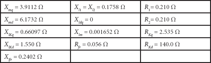
Symbols Meaning


- *Corresponding author: [email protected]