
15.12. Static membrane compliance
At very low frequencies, all inertial and resistive elements have very little effect and can therefore be removed from the analogous circuit of Fig. 15.16 to obtain that shown in Fig. 15.17.
To obtain the static membrane and negative compliances C
MD0 and −
C
ME0 respectively, we solve the static (in vacuo) membrane wave equation for the displacement η(w) versus the radial ordinate w
 (15.68)
where f
D0 is the static membrane driving force, which is given by
and β is the electromechanical conversion factor, which is given by

We have referred the negative capacitance
−C
E
to the mechanical side in Eq. (15.68) so that it becomes a negative mechanical compliance
We solve Eq. (15.68) to obtain
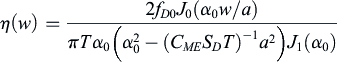 (15.72)
where α
0 is the first zero of the Bessel function J
0. From this we see that the displacement becomes indeterminate when
Hence for stability,
 (15.74)
The average displacement is given by
 (15.75)
Hence, the displacement at the center is about 2.3 times the average, and the total combined static compliance is given by
 (15.76)
so that
Hence, from Eqs. (15.71) and (15.78), the static negative capacitance is related to the dynamic negative capacitance by
..................Content has been hidden....................
You can't read the all page of ebook, please click here login for view all page.