
2.4. Solution of wave equation for air in a tube terminated by an impedance
For this example of wave propagation, we shall consider a hollow cylindrical tube, terminated at one end (x
=
0) by an impedance Z
T
and at the other (x
=
l) end by a flat vibrating piston (see Fig. 2.4). Alternatively, we could have interchanged the positions of the piston and termination impedance, but the arrangement shown has been chosen because it simplifies the equations. For example, in the case of a rigid termination the particle velocity is shown to be proportional to sin x as opposed to sin (l
−
x). However, care needs to be taken when calculating the impedance where the velocity has to be taken as that in the negative x direction. The angular frequency of vibration of the piston
is ω, and its rms velocity is
 at x
=
l. We shall assume that the diameter of the tube is sufficiently small so that the waves travel down the tube with plane wave fronts. For this to be true, the ratio of the wavelength of the sound wave to the diameter of the tube must be greater than about 6.
at x
=
l. We shall assume that the diameter of the tube is sufficiently small so that the waves travel down the tube with plane wave fronts. For this to be true, the ratio of the wavelength of the sound wave to the diameter of the tube must be greater than about 6.

Particle velocity
The form of solution we shall select is Eq. (2.48). If l is the length of the tube, then at x
=
l the particle velocity must be equal to the velocity
of the piston. The boundary conditions are:
so that
At x
=
0,
where the pressure is taken from Eq. (2.46). Note that velocity is negative here because it is in the reverse x direction. Hence
Transmitted and reflected pressures
Remember that
Hence
and
where
 is the transmitted pressure magnitude and
 is reflected pressure magnitude. The amount of sound reflected depends on how the tube is terminated. The reflection coefficient Γ is given by
In some places along the tube, the reflected wave will interfere constructively with the transmitted wave, thus producing a pressure maximum, and at others it will interfere destructively causing a pressure minimum. If the reflection is 100%, these maxima and minima become antinodes and nodes respectively. We shall examine these in greater detail in the next paragraph, which describes the case of a rigid termination. The ratio of maximum to minimum pressure along the tube is given by the Standing Wave Ratio or SWR where
Table 2.1

Of particular interest are the cases where (1) the pressure is zero at the termination (resilient termination), (2) the termination impedance is equal to the characteristic impedance of the tube (anechoic termination), and (3) the velocity is zero at the termination (rigid termination). All three cases are summarized in Table 2.1. The first case produces maximum negative reflection (that is, with reversed phase), the second zero reflection, and the third maximum positive reflection.
Sound-proofing materials are often defined by the absorption coefficient α, which is given by
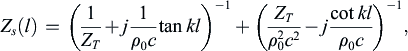
Impedance
The specific acoustic impedance Z
s
along the tube is then given by the ratio of pressure to velocity:
 (2.60)
Let us now recast this equation into two series impedances, as seen at the piston:
 (2.61)
the equivalent circuit for which is shown in Fig. 2.5.

Amazingly, a tube with any termination impedance Z
T
can be represented by the impedance of a blocked tube (with Z
T
=
∞) in series with an open tube (with Z
T
=
0) and two external impedances connected across them, which are related to the termination impedance Z
T
and characteristic impedance ρ
0
c. However, this makes more sense when we consider that when the impedance of the open tube is zero, the impedance of the blocked tube is infinite and vice versa. Hence the impedance seen between the input terminals simply alternates between Z
T
and (ρ
0
c)2/Z
T
as we sweep the piston generator frequency, which is entirely consistent with the standing wave ratio. When Z
T
=
ρ
0
c, the two series impedances are the complex conjugates of each other and we just see the characteristic impedance ρ
0
c at the input terminals. We shall use equivalent circuits extensively in this text. Also, it will be shown in Figs. 10.6 and 10.7 how the impedances of a blocked tube and open tube respectively may be represented by arrays of electrical circuit elements.
Impedance measurement
If we place two probe microphones in the tube, with one at x
=
l
1 and the other at x
=
l
2, then the ratio of the pressures
 and
and
 is given by
which is independent of
. The termination impedance is then given by
which is the principle of an impedance tube, which is used for measuring samples of material for which the impedance is unknown. An elegant feature of the method is that the measurement is independent of the piston velocity or actual magnitudes of the
pressures. Only the relative pressure ratio is needed to calculate the impedance. However, when the impedance is a large multiple (or small fraction) of ρ
0
c, the calibration of the microphones becomes very critical, as does the accuracy of the distances l
1 and l
2 between them and the sample.
Rigid termination (infinite impedance)
or
Refer to Fig. 2.6. If the length l and the frequency are held constant, the particle velocity will vary from a value of zero at x
=
0 to a maximum at x
=
λ/4, that is, at x equal to one-fourth wavelength. In the entire length of the tube the particle velocity varies according to a sine function.
Between the end of the tube and the λ/4 point, the oscillatory motions are in phase. In other words, there is no progressive phase shift with x. This type of wave is called a standing wave [5] because, in the equation, x and ct do not occur as a difference or a sum in the argument of the exponential function. Hence the wave is not propagated. In cases where there are absolutely no losses, the term stationary wave [5] is also used, although this can only be approximated in practice.
In the region between x
=
λ/4 and x
=
λ/2, the particle velocity still has the same phase except that its amplitude decreases sinusoidally. At x
=
λ/2, the particle velocity is zero. In the region between x
=
λ/2 and x
=
λ the particle velocity varies with x
according to a sine function, but the particles move 180
degrees out of phase with those between 0 and λ/2. This is seen from Eq. (2.64), wherein the sines of arguments greater than π are negative.

If we fix our position at some particular value of x and assume constant l, then, as we vary frequency, both the numerator and denominator of Eq. (2.64) will vary. When kl is some multiple of π, the particle velocity will become very large, except at x
=
l or at points where kx is a multiple of π, that is, at points where x equals multiples of λ/2. Then for kl
=
nπ
Eq. (2.64) would indicate an infinite velocity under this condition. In reality, the presence of some dissipation in the tube, which was neglected in the derivation of the wave equation, will keep the particle velocity finite, though large.
The particle velocity
 will be zero at those parts of the tube where kx
=
nπ and n is an integer or zero [7]. That is,
will be zero at those parts of the tube where kx
=
nπ and n is an integer or zero [7]. That is,
In other words, there will be planes of zero particle velocity at points along the length of the tube whenever l is greater than λ/2.
Some examples of the particle velocity for l slightly greater than various multiples of λ/2 are shown in Fig. 2.7. Two things in particular are apparent from inspection of these graphs. First, the quantity n determines the approximate number of half wavelengths that exist between the two ends of the tube. Secondly, for a fixed
, the maximum velocity of the wave in the tube will depend on which part of the sine wave falls at x
=
l. For example, if l
−
nλ/2
=
λ/4, the maximum amplitude in the tube will be the same as that at the piston. If l
−
nλ/2 is very near zero, the maximum velocity in the tube will become very large.
Let us choose a frequency such that n
=
2 as shown. Two factors determine the amplitude of the sine function in the tube. First, at x
=
l the sine curve must pass through the point u
0. Second, at x
=
0 the sine curve must pass through zero. It is obvious that one and only one sine wave meeting these conditions can be drawn so that the amplitude is determined. Similarly, we could have chosen a frequency such that n
=
2, but where the length of the tube is slightly less than two half wavelengths. If this case had been asked for, the sine wave would have ended with a negative instead of a positive slope at x
=
l.

Sound pressure
The sound pressure in the tube may be found from the velocity with the aid of the equation of motion Eq. (2.4a), which, in the steady state, becomes
The constant of integration in Eq. (2.68), resulting from the integration of Eq. (2.4a), must be independent of x because we integrated with respect to x. The constant then represents an increment to the ambient pressure of the entire medium through which the wave is passing. Such an increment does not exist in our tube, so that in Eq. (2.68) we have set the constant of integration equal to zero. Integration of Eq. (2.68), after we have replaced
by its value from Eq. (2.64), yields
or
This result could alternatively have been obtained by setting Z
T
=
∞ in Eq. (2.58). The pressure
 will be zero at those points of the tube where kx
=
nπ
+
π/2 (where n is an integer or zero),
will be zero at those points of the tube where kx
=
nπ
+
π/2 (where n is an integer or zero),
The pressure will equal zero at one or more planes in the tube whenever l is greater than λ/4. Some examples are shown in Fig. 2.8. Here again, quantity n is equal to an approximate number of half wavelengths in the tube.
Refer once more to Fig. 2.7, which is drawn for t
=
0. The instantaneous particle velocity is at its maximum (as a function of time). By comparison, in Fig. 2.8 at t
=
0, the instantaneous sound pressure is zero. At a later time t
=
T/4
=
1/(4f), the instantaneous particle velocity has become zero and the instantaneous sound pressure has reached its maximum. Eqs. (2.64) and (2.69) say that whenever kx is a small number, the sound pressure leads by one-fourth period behind the particle velocity. At some other places in the tube, for example when x lies between λ/4 and λ/2, the sound pressure lags the particle velocity by one-fourth period.
To see the relation between p and u more clearly, refer to Fig. 2.7 and Fig. 2.8, for the case of n
=
2. In Fig. 2.7, the particle motion is to the right whenever u is positive and to
the left when it is negative. Hence, at x
=
λ/2, the particles on either side are moving toward each other, so that one-fourth period later the sound pressure will have built up to a maximum, as can be seen from Fig. 2.8. At the 2λ/2 point, the particles are moving apart, so that the pressure is dropping to below barometric as can be seen from Fig. 2.8.

Fig. 2.7 and Fig. 2.8 also reveal that, wherever along the tube the magnitude of the velocity is zero, the magnitude of the pressure is a maximum, and vice versa. Hence, for maximum pressure, Eq. (2.67) applies.
Specific acoustic impedance
It still remains for us to solve for the specific acoustic impedance Z
s
, at any plane x, in the tube. Taking the ratio of Eq. (2.69) to Eq. (2.64) or setting Z
T
=
∞ in Eq. (2.60) yields
where X
s
is the reactance, and where we have set
That is, l′ is the distance between any plane x in Fig. 2.4 and the rigid end of the tube at 0. The −
j indicates that at low frequencies where cot kl′
≈
1/kl′, the particle velocity leads the pressure in time by 90
degrees and the reactance X
s
is negative. At all frequencies the impedance is reactive and either leads or lags the pressure by exactly 90
degrees depending, respectively, on whether X
s
is negative or positive. The reactance X
s
varies as shown in Fig. 2.9. If the value of kl′ is small, we may approximate the cotangent by the first two terms of a series
This approximation is valid whenever the product of frequency times the distance from the rigid end of the tube to the point of measurement is very small. If the second term is very small, then it may be neglected with respect to the first.

Let us see how small the ratio of the distance l′ to the wavelength λ must be if the second term of Eq. (2.74) is to be 3% or less than the first term. That is, let us solve for l′/λ from
which gives us
In other words, if cot kl′ is to be replaced within an accuracy of 3% by the first term of its series expansion, l′ must be less than one-twentieth wavelength in magnitude.
Hence, the specific acoustic impedance of a short length of tube can be represented as a “capacitance” called specific acoustic compliance, of magnitude C
s
=
l′/ρ
0
c
2. Note also that C
s
=
l′/γP
0, because of Eq. (2.19).
The acoustic impedance is of the same type, except that an area factor appears so that
where V
=
l′S is the volume and S is the area of cross section of the tube. C
A
is called the acoustic compliance and equals V/ρ
0
c
2. Note also that C
A
=
V/γP
0, from Eq. (2.19).
Example 2.3. A cylindrical tube is to be used in an acoustic device as an impedance element. (a) The impedance desired is that of a compliance. What length should it have to yield a reactance of 1.4
×
103 rayls at an angular frequency of 1000
rad/s? (b) What is the relative magnitude of the first and second terms of Eq. (2.74) for this case?
Solution: The reactance of such a tube is
Hence, l′
=
0.1
m.

..................Content has been hidden....................
You can't read the all page of ebook, please click here login for view all page.