
9.11. Infinite exponential horn
Theoretical considerations
The equation describing the cross-sectional area S(x) as a function of the distance x along the axis is
where S
T
is the area of the throat, which is located at x
=
0. In the steady state, the Helmholtz equation for the exponential horn is obtained by inserting S(x) from Eq. (9.39) into Eq. (2.27) to yield
 (9.40)
where
and
-
 is harmonically varying sound pressure at a point along the length of the horn in Pa. (It is assumed that the pressure is uniform across the cross section of the horn.)
 - c is speed of sound in m/s.
- x is distance along the length of the horn from the throat in m.
- m is flare constant in m −1. Obviously, m determines the magnitude of the second term of the equation above, which expresses the rate at which the sound pressure changes with distance down the horn. If m = 0, Eq. (9.40) becomes the equation for propagation in a cylindrical tube, i.e., a horn with zero flare.
- S T is cross-sectional area of the throat in m2.
- S is cross-sectional area at x in m2.
The general solution for the pressure in an exponential horn of any length is
where
 denotes the pressure amplitude of the forward traveling wave and
 that of the backwards traveling wave. The tilde replaces the factor e
jωt
. Using Eq. (2.122), the velocity is given by
that of the backwards traveling wave. The tilde replaces the factor e
jωt
. Using Eq. (2.122), the velocity is given by
 (9.43)
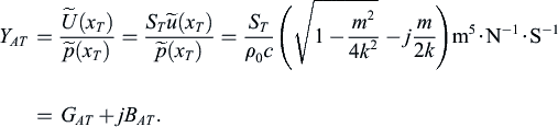
Throat impedance
Noting that in an infinite horn there are no reflections from the mouth, we set
 to obtain the acoustic throat admittance, which is the ratio of the volume velocity
 to the pressure
at x
=
x
T
, so that
to the pressure
at x
=
x
T
, so that
 (9.44)
The acoustic impedance Z
=
1/Y
AT
at the throat is
 (9.45)
The real and imaginary parts of Z and Y
AT
behave alike with frequency and differ only by the magnitude (S/ρ
0
c)2 and the sign of the imaginary part. Note also that, unlike with the parabolic or conical horns, this impedance is independent of the distance x along the axis of the horn. Next, we shall examine how varying the flare constant m affects the acoustic impedance Z
AT
.
Flare constant and throat impedance
When the flare constant m is greater than 4π divided by the wavelength (m
>
2k, low frequencies), the acoustic resistance R
AT
and the acoustic reactance X
AT
, at the throat of the horn where the area is S
T
, are
 (9.46)
When the flare constant m equals 4π divided by the wavelength, the acoustic resistance, and reactance are
 (9.47)
For all cases where m is less than 4π divided by the wavelength (m
<
2k, high frequencies), the acoustic resistance and reactance at any point x along the horn where the cross-sectional area is S are
 (9.48)
where C
AT
=
2S
T
/ρ
0
c
2
m.
For very high frequencies, the reactance approaches zero and the resistance approaches ρ
0
c/S
T
or ρ
0
c/S in general. This is also the impedance for a plane progressive sound wave in a tube of uniform cross section S.
Cutoff frequency
The special case of m
=
4π/λ occurs at a frequency that we shall designate as f
c
, where
This frequency f
c
is called the cutoff frequency because, for frequencies lower than this, no power will be transmitted down the horn, i.e., the impedance at all positions along the horn is purely reactive (see Eq. 9.46). The throat impedance of an infinite exponential horn is plotted in Fig. 9.9.
To obtain the acoustic impedance at the throat of the horn in terms of the cutoff frequency, we observe that f
c
/f
=
m/2k. Substituting in Eq. (9.45) yields
 (9.50)
where
Graphs of two quantities A and B that are directly proportional to the resistive and reactive parts of the acoustic impedance at the throat of an infinitely long exponential horn are shown in Fig. 9.8. The quantities A and B also are directly proportional to the real and imaginary parts of the acoustic admittance at the throat. The relations among A, B, R
AT
, X
AT
, G
AT
, and B
AT
are given on the graph. When the frequency is greater than approximately double the cutoff frequency f
c
, the throat impedance is substantially resistive and very near its maximum value in magnitude.
..................Content has been hidden....................
You can't read the all page of ebook, please click here login for view all page.