

Practical agile integration
In this chapter we progressively build up a scenario that demonstrates use of the integration capabilities to solve some common modern application design challenges using agile integration techniques.
We begin by exposing data from a traditional data source over RESTful APIs. Then, we gradually build up to more sophisticated ways of making that same data, and data from other applications, available via modern microservice-style components.
We have arranged each section to be completely independent of the others, so there is no need to work through the sections in order. Each section is self-sufficient, and provides everything needed to build it out.
|
Note: The solution in each section is complete for a specific scenario. However, none of these solutions forms a global, end-to-end solution for agile integration.
|
This chapter has the following sections. See 6.1, “Introduction” on page 170 for a detailed description of each section:
•Introduction
•Application Integration to front a datastore with a basic API
•Expose an API using API Management
•Messaging for reliable asynchronous data update commands
•Consolidate the new IBM MQ based command pattern into the API
•Advanced API security
•Create event stream from messaging
•Perform event-driven SaaS integration
•Implementing a simple hybrid API
•Implement event sourced APIs
•REST and GraphQL based APIs
•API testing
•Large file movement using the claim check pattern
6.1 Introduction
The scenarios for this chapter are based on a common theme we see with customers. We often begin with a requirement from the business to provide access to a back-end system by fronting it with an API. However, this apparently simple requirement grows in complexity over time, typically to cater to increasingly challenging non-functional requirements such as performance and availability.
Our scenario begins with the basic requirement to make the data from a table in a traditional database available as an API. In our scenario this is a simple single table that holds information about "Products." But in a real scenario it could be multiple tables that are joined in various ways to provide product catalog information.We achieve this integration in its most basic form in section 6.2, “Application Integration to front a data store with a basic API” on page 173. Deliberately, we do this using the fine-grained cloud native style deployment that is fundamental to agile integration as discussed earlier in this book. This ensures that integrations are isolated from on another so they can be changed and scaled independently. This improves agility, resilience, and optimization of the underlying resources.
As shown in Figure 6-1, we then look at improving the exposure of the API, using API management to make the API more discoverable, enable consumers to self-subscribe to use APIs, and enable us to track and control usage of the APIs. This is the topic of 6.3, “Expose an API using API Management” on page 189.

Figure 6-1 Improving the exposure of the API using API management
As a result, we now have a self-contained business component that provides API-based access to product data, that can easily be reused to bring that data into new solutions.
Next comes the non-functional requirements. Although our integrations have been designed in a cloud native way such that they can scale, and indeed scale independently, the back-end database is still a bottleneck. There are times when the number of updates being made to the Product table is affecting the performance of the reads on that table. Indeed, the writes themselves start to take more time. The effect on the user experience of applications based on this API is becoming noticeable, reducing customer satisfaction. With our single-table scenario, clearly these performance issues would be unlikely to occur. But we can imagine a real multi-table scenario — with searches performing multi table joins, and updates
locking multiple tables in order to perform transactional updates with integrity — where performance issues of this type soon become an issue. We decide to tackle this problem on two fronts.
•Change the interaction pattern for updates to be asynchronous:
We change the way updates are performed such that they are done asynchronously after the requests has been acknowledged. Consumers of the API then get an immediate response to assure them that the updates will occur, enabling a much more responsive user interface. Furthermore, it means we can now throttle the rate at which we apply those updates to the database such that they have less effect on the performance of reads. We enable this in 6.4, “Messaging for reliable asynchronous data update commands” on page 207. We provide a route to performing updates asynchronously in a "fire-and-forget" pattern by placing them in a "command store" (in our case, IBM MQ), then responding immediately back to the caller with an acknowledgment. We then make this accessible to a broader audience in 6.5, “Consolidate the new IBM MQ based command pattern into the API” on page 258 by bringing the asynchronous update back into the HTTP based API. Effectively we hide the use of IBM MQ behind the scenes. It should be noted that we have now introduced eventual consistency (rather than immediate consistency). Updates don't occur at the time of the update request. The applications using the API need to take this into account in their design, but as a result they can enjoy the performance improvements.
•Provide a read-optimized datastore:
Now that Product data is so easily available through our API, it is being used in many new and innovative ways. Unfortunately, the way that the data is stored in the current database is poorly suited to the types of queries now being performed. These new queries perform slowly even with our move to asynchronous updates as the issues are more related to how data is aggregated. This may simply be because the new consumers want a very different representation of the Product data. Or it could be because it needs to be combined with other data such as Price before it is useful. To solve this, we decide to implement a new datastore, that is specifically optimized for these new queries. We of course need to keep this new datastore in sync with the original master Product database. To do this, in 6.7, “Create event stream from messaging” on page 321 we show how we can keep a note of all the changes that happen to the Product database and place them in an event store, which in our case is provided by IBM Event Streams. These updates can then be asynchronously applied to the read-optimized datastore as discussed in 6.10, “Implement event sourced APIs” on page 366. Note this further exacerbates the eventual consistency between the updates to the main database, and reads from the read-optimized datastore. However, since users of our API have already had to learn to code for this behavior when we separated out the commands, it should have minimal effect on their applications.
Figure 6-2 on page 172 shows the enhanced integration pattern with asynchronous updates and optimized reads.

Figure 6-2 Performance and availability improvements through eventual consistency patterns
From an integration standpoint, the patterns we've introduced are many decades old. Yet, modern application developers might see this set of patterns implemented together and recognize that it is an implementation of CQRS. CQRS stands for Command Query Responsibility Segregation. It essentially means providing independent paths for commands (create, update, delete) and queries (reads, searches, and so on), just as we have done in our scenario. Because this concept is familiar to many developers, we have tried to use the associated terms in our scenario where appropriate.
From the outside, our logical Product component looks much the same as it did in our first iteration, enabling access to Product data via an API. However, using agile integration techniques:
•The API is now more easily discovered, used, and controlled.
•The implementation is more performant and scalable.
•The patterns give us flexibility to rapidly implement new requirements without destabilizing what we have.
So, we have had a detailed look at how integration capabilities can be involved in the implementation of a reusable business component, from a simple API exposure through to a full CQRS-based implementation. Next, we look at how these business components might interact with one another.
In 6.9, “Implementing a simple hybrid API” on page 344, we look at our new API from the consumers point of view. We consider how much easier exposing something as an API makes the creation of new solutions. In this case we enable a non-integration specialist to build a new API based on existing APIs in order to create a further unique capability.
Going back to the events that we were using internally within the component, let’s consider how they might also be valuable outside the component. The events might become a reusable capability in the same way that our API is. Exposing events beyond the component would enable, for example, a separate application to use the same event-sourced programming models in their own implementations, maintaining their own read-optimized data stores. In 6.8, “Perform event-driven SaaS integration ” on page 327, we extend this thought. We consider an example of how non-integration specialists could use events from our component as triggers on new integrations with modern Software-as-a-Service applications.
We then return to our exposed API and consider how we might want to improve that exposure as we make it available to broader audiences. We explore these issues:
•How to implement the OAuth security model to enable authentication to be handled by a separate provider ([6.6, “Advanced API security” on page 275).
•How to introduce alternative API exposure styles such as GraphQL to give consumers more flexibility in how they consume the data (6.11, “REST and GraphQL based APIs” on page 380).
•How to perform effective, repeatable API testing to ensure that the API behavior remains consistent as we add enhancements (6.12, “API testing” on page 397).
Finally, we consider what to do when the data we need to move between applications is not appropriate for APIs or events. A common example in modern applications is files such as video media. It makes no sense for these large files to travel over an API, or events due to their size, often greater than a Gigabyte. In these circumstances a more logical approach is the claim check pattern explored in 6.13, “Large file movement using the claim check pattern” on page 409. In that example, we store the object in a place that the cloud can reference, then pass only the reference. Of course, the file's content must move to its destination eventually. So, we also discuss the benefits of FASP (the Fast and Secure Protocol) for getting large data across significant network distances.
|
Note: For some of the following exercises, we use IBM Cloud Pak for Integration. If you do not currently have access to an environment, see section 5.1.4, “Getting access to IBM Cloud Pak for Integration for the exercises” on page 145.
|
6.2 Application Integration to front a data store with a basic API
In this section, we demonstrate how to use IBM App Connect to expose a datastore as a RESTful API. The key points implemented here are as follows:
•Fine grained, container-based deployment of integrations, enabling independent maintenance, elastic scaling, and isolated resilience.
•Code free data mapping from a REST data model to database table definition.
•Configuration-based protocol conversion from HTTP to JDBC.
The objective here is not to show in detail how to create the integrations themselves since there is plenty of existing material on building integrations. The key thing to note is that no code is required for these simple integrations, just a simple integration flow that contains a map.
Instead, we want to focus on what it looks like to deploy these to a cloud native style. As such, we begin the exercise with a blank cloud environment, and we deploy the integrations directly to it. There is no preparatory stage of building a shared infrastructure as we would have traditionally. Instead, each integration that is deployed provides its own discrete integration runtime, and the rest (such as HA and scaling) is provided by the container orchestration platform.

Figure 6-3 Deployment of the API across two separate containers
We deliberately demonstrate deployment of this API across two separate containers as shown in Figure 6-3. That way, you see that they could be changed and scaled separately and could have different resilience models.
We create two REST applications in the IBM App Connect Toolkit. One is for Create, Update, and Delete (commands) to a table on IBM Db2 called Products. The other deals exclusively with Read (queries). The flows for the two REST applications are already built and available at this GitHub site:
https://github.com/IBMRedbooks/SG248452-Accelerating-Modernization-with-Agile-Integration/tree/master/chapter6/6.1
https://github.com/IBMRedbooks/SG248452-Accelerating-Modernization-with-Agile-Integration/tree/master/chapter6/6.1
The applications can be opened in the Toolkit by importing the following files:
Alternatively, you can build them yourself as described here:
https://www.ibm.com/support/knowledgecenter/en/SSTTDS_11.0.0/com.ibm.gdm.doc/cm28851_.htm
Each REST application includes:
•JDBC Connection to a Db2 database that uses a policy
•A Db2 database called PRODUCTS, with a schema called PRDCTS and a table called Products as defined in the Products data model in https://github.com/IBMRedbooks/SG248452-Accelerating-Modernization-with-Agile-Integration/blob/master/chapter6/products_data_model.json
•Swagger that describes the data model for each path
•Unique sub flows for each relevant operation (Create, Read, Update, Delete)
Each subflow has an input, a mapping node and an output. Figure 6-4 shows the REST API operation subflow.

Figure 6-4 REST API Operation Subflow
Figure 6-5 shows the Queries flow.

Figure 6-5 Get Product Operation Mapping Node
Figure 6-6 on page 175 through Figure 6-8 on page 176 show the Command flows.

Figure 6-6 Delete Product Operation Mapping Node

Figure 6-7 Post Product Operation Mapping Node

Figure 6-8 Put Product Operation Mapping Node
6.2.1 Db2 setup
For the application in this section to function correctly, a Db2 database needs to be set up for the IBM App Connect flow to operate against.
Next we must create a Db2 instance using the following instructions: https://github.com/IBM/Db2/tree/develop/deployment
1. Configure the instance with the following parameters:
a. Choose a release name.
b. Select a namespace.
Note: This value does not need to be the same namespace where the IBM App Connect container will be deployed.
Note: This value does not need to be the same namespace where the IBM App Connect container will be deployed.
c. Set the Database Name to PRODUCTS.
d. Set the Db2 instance name to db2inst1.
e. Provide a Password for Db2 instance, for example passw0rd.
f. Persistence is optional.
g. Do not select the Db2 HADR mode.
2. After the deployment is complete, observe that ports 50000 and 55000 are both exposed via two types of Kubernetes services, NodePort and ClusterIP in the OpenShift console,
|
Note: For a distinction between NodePort and ClusterIP service types, refer to section 4.4.2, “Container orchestration” on page 107.
|
3. You can use Db2-compatible database client to connect to the Db2 instance via the NodePort service, and to verify that the database called PRODUCTS has been successfully created. In the next section, we use the IBM App Connect Toolkit in the Database Development view.
In the remainder of the chapter, we connect to the Db2 instance by using a policy definition in IBM App Connect. The definition leverages the ClusterIP service, as described in 6.4.6, “Policy definitions” on page 249.
6.2.2 Db2 table setup
To set up a Db2 table for the samples in this chapter, we use the IBM App Connect Toolkit in the Database Development view to connect to the Db2 instance that we spun up in 6.2.1, “Db2 setup” on page 176.
The following tasks are performed on the IBM App Connect Toolkit version 11.0.0.5.
1. Open the toolkit and navigate to the Database Development View. See Figure 6-9 on page 178.

Figure 6-9 Switch to Database Development View

Figure 6-10 New Database Connection
3. In the connection details, select the DB2 for Linux, UNIX, and Windows option in the menu and put the database details from the previous section. Remember to use the NodePort service exposing the container port 50000 for the Db2 instance.
The service is typically exposed on the Proxy Node IP address of Fully Qualified Domain Name. See Figure 6-11 on page 179.

Figure 6-11 Connection details
4. The Products database connection now exists in the Database Connections sidebar. Right click Products and select New SQL Script. See Figure 6-12 on page 180.

Figure 6-12 New SQL Script
5. To create a PRODUCTS table in the PRODUCTS database, type the following SQL command shown in Example 6-1 into the newly opened SQL script.
Example 6-1 SQL script
CREATE TABLE PRODUCTS
(
last_updated varchar(255) NOT NULL,
part_number int NOT NULL,
product_name varchar(255),
quantity int,
description varchar(255),
PRIMARY KEY (part_number)
);

Figure 6-13 Run SQL
This should result in a success report as shown in Figure 6-14 on page 182.

Figure 6-14 - SQL success report
7. You can now insert a new row into the table using the following SQL command and again selecting the Run SQL command as previous.
INSERT INTO PRODUCTS ( last_updated, part_number, product_name, quantity, description)
VALUES ('2019-08-01T09:57:34.265Z', 12, 'duck', 100, 'a waterbird with a broad blunt bill, short legs, webbed feet, and a waddling gait');
8. We can check that the entry has been successfully inserted by using the SELECT SQL command.
SELECT * FROM PRODUCTS
Figure 6-15 shows the SELECT SQL query result.

Figure 6-15 SELECT SQL query result
6.2.3 Swagger definitions
In this section, we package the project files into a BAR file for each application as shown in the following web pages:
Then we create a new server for each. In this chapter we want to use the user interface to achieve this. Later, we see how this can be automated by using pipeline deployment in section 7.5, “Continuous Integration and Continuous Delivery Pipeline using IBM App Connect V11 architecture” on page 465.
1. Log in to the IBM Cloud Pak for Integration instance and the IBM App Connect dashboard. In this view we click Add server as shown in Figure 6-16.

Figure 6-16 Add server in the IBM App Connect dashboard

Figure 6-17 Add a BAR file
3. Next, select the BAR file from the local directory where it is saved and select Choose. See Figure 6-18 on page 184.

Figure 6-18 Choose the relevant BAR file
4. The BAR file is displayed in the user interface, and you can confirm that the correct file has been uploaded, then select Continue. See Figure 6-19.

Figure 6-19 BAR file shown in the user interface
5. In the next screen we copy the Content URL and select Configure release. See Figure 6-20 on page 185.

Figure 6-20 Get Content URL (ConfigureReleaseCopyContentURL)
6. The new page describes the helm chart to be used to deploy the new server into, confirm the Cloud Pak version and select Configure. See Figure 6-21 on page 185.

Figure 6-21 IBM App Connect Helm Chart
7. Type a Helm release name such as redbook-read for the database query BAR and redbook-commands for the database commands BAR. In the Target namespace select icp4i before you read and accept the license agreement by checking, I have read and agreed to the license agreement. See Figure 6-22 on page 186.

Figure 6-22 Helm release name, target namespace and accepted license agreement
8. Paste the previously copied Content URL into the Content Server URL box. See Figure 6-23 on page 186.

Figure 6-23 Pasted Content URL
9. Type the IP address for the Master or Proxy node of the IBM Cloud Pak for Integration instance into NodePort IP box. See Figure 6-24 on page 186.

Figure 6-24 Deployment IP
10. For this example we need only a single replica. So, set the Replica count to ‘1’ and ensure that the Local default Queue Manager is deselected as shown in Figure 6-25 on page 187.

Figure 6-25 Replica Count 1 and Queue Manager deselected
11. After double checking the configuration, select Install.
12. A message confirming the starting of the installation is displayed. The message can be tracked in the helm release by redirecting through the View Helm Release button. See Figure 6-26 on page 187.

Figure 6-26 Helm Deployment successful start
13. The new services for the helm release is displayed. To see further details, including the exposed ports for the server, select the link redbook-read-ibm-ace-server-icip-prod or redbook-commands-ibm-ace-server-icip-prod depending on the BAR file that is being deployed. See Figure 6-27 on page 187.

Figure 6-27 Two services for the deployed IBM App Connect server
14. In Figure 6-28 on page 188 we can see the HTTP server exposed port (31016).

Figure 6-28 Exposed ports for the service
15. We can then use the port to create a test url to make a GET on the redbook-read server. In an API Connect Test and Monitor select a GET operation http://<ibm_cloud_ip>:<http_port>/database_query/v1/products which returns the records from the PRODUCTS table in the database. See Figure 6-29 on page 188.

Figure 6-29 Returned output from the PRODUCTS table
It is worth considering that the policy used in both BAR files is dependent on its reference to the datastore. This must be updated if the port of the database changes. It is possible to deploy the BAR directly to an existing empty server through the Toolkit and as the system gains maturity automated builds based on code repository pushes can be deployed.
We now have two BAR files deployed onto the Cloud that enable us to read/add/delete/update rows in the database. These bar files can be independently maintained and scaled, and can have separately defined availability models.
6.3 Expose an API using API Management
This section shows you how to expose an API using API Management, which brings the following benefits. (Not all of these issues are explored in detail in the example.)
•Discovery: Enable consumers to find the APIs they need, understand their specifications, learn how to use them, and experiment with them before committing to use them.
•Self-subscription: Allow consumers to self-subscribe to use the API using a revocable key.
•Routing: Hide the exact location of the API implementation, and enable version based routing.
•Traffic management: Provide throttling of inbound requests to the API on a per-consumer basis
•Analytics: Provide both consumers and providers with information regarding their API usage, response times and more.
In the first exercise we created the two basic implementations of the REST APIs. We now want to bring those together into a single consolidated API to simplify usage for the consumer. Furthermore, we want to provide API management capabilities as shown in Figure 6-30.

Figure 6-30 Providing API management capabilities
Having created the implementation of REST APIs in the previous section we now want to expose them through an API Management system. This gives the ability to manage how the APIs are consumed, how traffic can be limited and how exposure to external parties is properly handled.
6.3.1 Importing the API definition
There are two methods for exporting an IBM App Connect REST API to IBM API Connect.
Pushing from IBM App Connect to IBM API Connect
The first option is to make use of the Push REST APIs to API Connect... functionality which is available from the App Connect dashboard. This is documented in the IBM Knowledge Center: https://www.ibm.com/support/knowledgecenter/SSTTDS_11.0.0/com.ibm.etools.mft.doc/bn28905_.htm
|
Note: This functionality currently is possible in stand-alone instances of IBM App Connect to any given API Connect instance. Be aware that at the time of writing there was a limitation in IBM Cloud Pak for Integration deployments that meant a callback ‘POST’ to the IBM App Connect Server is not available.
|
Importing the API definition file
The second option is to import the API definition file manually.
Perform the following steps to import API to the Developer Workspace:
1. First, you must create the API. To do that, click on Develop APIs and Products. See Figure 6-31 on page 190.

Figure 6-31 API Manager main page

Figure 6-32 Import API to the developer workspace 1

Figure 6-33 Import API to the developer workspace 2

Figure 6-34 Import API to the developer workspace 3
|
Note: Download the swagger definition from https://github.com/IBMRedbooks/SG248452-Accelerating-Modernization-with-Agile-Integration/blob/master/chapter6/database_operations_swagger.json.
|
5. Click Browse and choose the Swagger definition that you have downloaded from GitHub. See Figure 6-35.

Figure 6-35 Import API to the developer workspace 4

Figure 6-36 Import API to the developer workspace 5

Figure 6-37 Import API to the developer workspace 6

Figure 6-38 Import API to the developer workspace 7
|
Descriptions:
Secure using Client ID - Select this option to require an Application to provide a Client ID (API Key). This causes the X-IBM-Client-Id parameter to be included in the request header for the API. When this option isselected, you can then select whether to limit the API calls on a per key (per Client ID).
CORS - Select this option to enable cross-origin resource sharing (CORS) support for your API. This allows your API to be accessed from another domain.
|

Figure 6-39 Import API to the developer workspace 8
6.3.2 Configuring the API
In this section we edit the API to include two different APIs from two microservices for the same business function. From a consumer point of view, it looks like a single API but it is actually connected to two different microservices at the back end.
6.3.3 Merging two application flows into a single API
We have now deployed the Commands swagger into the API Management service of API Connect, either through the App Connect push functionality or through a direct import of the API definition into API Connect.
This API and Product now displays the command operations for the database (Add, Update, Delete), but not the query (Read). We add this query manually by navigating to the API in API Connect.
1. Navigate to the API Manager API Definition in API Connect for database_operations and select Paths (Figure 6-40 on page 195) and the /products (Figure 6-41 on page 195) path name.

Figure 6-40 API Definition in API Connect

Figure 6-41 API definition in API Connect in Path
2. In the operations section, we select the Add button to include a get operation by toggling ON the get option and selecting Add. See Figure 6-42 on page 196.

Figure 6-42 Add the GET operation
3. Select the Get operation and give an Operation Id like getProducts and a Description like getProducts. See Figure 6-43 on page 197.

Figure 6-43 Set OperationID and Description
4. In the same page toggle ON the following; Override API Produce Types, application/json, Override API Consume Types, application/json. See Figure 6-44 on page 198.

Figure 6-44 Set the Produces and Consumes types
5. On the same page, we go to Response and select Add before you set Status Code to 200, Schema to object and Description to “The operation was successful”. See Figure 6-45.

Figure 6-45 Create a Response
6. Remember to Save the API before navigating to the Assemble view of the designer.
7. In the assemble view, we need to ensure that there is a Switch object to point to each of the four operations. If not, drag and drop the Switch object from the side panel into the assembly flow. See Figure 6-46 on page 199.

Figure 6-46 Add a Switch statement
8. We add a case condition for each of the path parameters. Click on the Switch in the assembly, and click the + Case button 3 times to give four conditions. Select each to Add the operation from a list of available operations, one to each case. See Figure 6-47.

Figure 6-47 Add Cases for each operation
9. For each operation we include a proxy for the POST, PUT, and DELETE operations and an invoke for the GET. The differences are described here:
https://chrisphillips-cminion.github.io/apiconnect/2017/07/17/Proxy-and-Invoke-What-is-the-difference-in-API-Connect.html.) Also see Figure 6-48.
https://chrisphillips-cminion.github.io/apiconnect/2017/07/17/Proxy-and-Invoke-What-is-the-difference-in-API-Connect.html.) Also see Figure 6-48.

Figure 6-48 Add Proxy and Invokes for each assembly path
10. In the POST, PUT, and DELETE proxies we include the ACE Commands Endpoint and the GET invoke includes the ACE Query Endpoint. See Figure 6-49 on page 201.

Figure 6-49 Define the required endpoints
11. Click Save.
Now that the API is ready to use, we can look at becoming the consumer of this API.
6.3.4 Add simple security to the API
In this section, we show you how to secure the API.
Configure API key security
In this section we will:
1. Define the API with simple security like API key and API secret
2. Publish the product
3. Test the API
Define simple security
Perform the following steps:

Figure 6-50 Defining the security 1
2. Under name type secret, choose APIKey for the Type and Located in Header. Then click Save. See Figure 6-51.

Figure 6-51 Defining the security 2
Your definitions should look like Figure 6-52 on page 203.
Figure 6-52 Defining the security 3
Publish the product
Perform the following steps to publish the product:
1. Click Develop from the left side menu, then click the ellipsis (…) beside the API that you want to publish and click Publish. See Figure 6-53.

Figure 6-53 Publishing the product 1

Figure 6-54 Publishing the product 2

Figure 6-55 Publishing the product 3
Test the product
1. Now you can test the API. Go to Assemble and click the highlighted box in Figure 6-56 on page 205.

Figure 6-56 Testing the API 1

Figure 6-57 Testing the API 2
3. Choose the operation to test. Here, we try the get operation. See Figure 6-58.

Figure 6-58 Testing the API 3
4. Click Invoke. You receive the response from the back end with 200 OK. See Figure 6-59 on page 207.

Figure 6-59 Testing the API (Response)
This was only a simple security using the API Key.
We have shown a basic invocation of the API using the internal testing mechanism. Of course, real consumers would first need to discover the API through the developer portal, then subscribe to use it. We cover this more formal discovery and subscription in “Subscribing to products” on page 295.
6.4 Messaging for reliable asynchronous data update commands
In previous sections, we explored how to move existing centralized ESB based integrations into an Agile Integration paradigm. To do this, we broke the different integrations apart and exposed them through API management. This is a good start, but as part of your overall application modernization strategy, new integration patterns will also emerge.
A good example is event-based programming models for updates. For reasons such as performance or availability of a data source, you might decide to move toward these models and away from traditional synchronous data updates.
In the first section, we deliberately split the traditional CRUD (create, read, update, delete) into separate models for commands. The separate models make changes to data (create, update, delete) and to the other operations that query (search/read) data, to enable them to be changed and scaled independently. However, they were still synchronous in nature, dependent on the datastore's performance and availability.
We can make use of this separation and independently refactor the change operations to be asynchronous, without touching the query path. In our case, we do this by introducing IBM MQ instead of HTTP as the mechanism for the update. Just to be clear what we mean by this, we are not talking about changing only the transport from HTTP to IBM MQ. We are also changing the interaction pattern from request/response to fire and forget. This way, after a request has been made to change data, we can respond immediately to the calling system that the request has been received. We do not have to wait for it to be completed. So, we are no longer dependent on the back-end systems availability or performance. IBM MQ's assured delivery means that we can be confident that it will eventually happen. Furthermore, we can throttle and control when the updates are applied, so that in busy periods they do not affect the performance of queries.
Clearly this model introduces challenges. We don't know exactly when the update will occur. And there might be other updates from other consumers, too. So, we can never be entirely sure of the status of the data in the back-end system. Nowadays we use the term eventual consistency to describe this situation. Clearly it is better suited to some business scenarios than others. In our example, we decided that the increased availability and response time on updates to our "product" data, and the potentially more consistent performance on queries, are more important than knowing that the data is 100% consistent all the time.
The CQRS (Command Query Responsibility Segregation) pattern has become popular in recent years. Data changes (commands) and reads (queries) are treated as separate implementations, to improve reliability and performance. The integrations for these two halves were already separate, but they were both acting synchronously on the same data source. What we are doing in this section can be described as implementing the "command" part of this pattern. In other words, we change the synchronous data changes into a series of asynchronous commands. In later sections, we look at creating even more separation on the "query" side.
Figure 6-60 on page 209 illustrates this pattern.

Figure 6-60 Command and Query pattern
In this section, we explore how you can use IBM MQ and IBM App Connect to implement the Command side of this pattern.
6.4.1 Enable create, update, delete via commands
One of the first choices you must make when implementing this side of the pattern is which protocol mechanism to use for sending the commands to the corresponding component.
Because Commands represent a specific action that must occur, we use a one-way “PUT” to an IBM MQ queue. This approach allows us to decouple the requester from the implementation. At the same time, it provides a reliable messaging platform that allows event collaboration among the different services. IBM MQ's assured "exactly once" delivery of messages is ideal here. And its ability to participate in a transaction with a database offers even more options as we discuss later.
For a clean design, you need three queues that represent each one of the commands. In addition, it is recommended to have two extra queues, one to store potential errors and a second one to log the activity. The second queue can be replaced by any other logging framework that is available in the platform, but we use it here for illustration purposes.
In the next section we show you how to create an IBM MQ queue manager, and the necessary queues for this part of the solution. However, you might already have an existing IBM MQ queue manager (or already have the skills to create one). Example 6-2 on page 210 shows the list of IBM MQ commands that you need to create the corresponding queues and the needed authorization records:
Example 6-2 List of IBM MQ commands
DEF QLOCAL(DB.LOG)
DEF QLOCAL(DB.ERROR)
DEF QLOCAL(DB.CREATE) BOTHRESH(1) BOQNAME(DB.ERROR)
DEF QLOCAL(DB.UPDATE) BOTHRESH(1) BOQNAME(DB.ERROR)
DEF QLOCAL(DB.DELETE) BOTHRESH(1) BOQNAME(DB.ERROR)
SET AUTHREC PROFILE('DB.LOG') OBJTYPE(QUEUE) principal('user11') AUTHADD(ALL)
SET AUTHREC PROFILE('DB.ERROR') OBJTYPE(QUEUE) principal('user11') AUTHADD(ALL)
SET AUTHREC PROFILE('DB.CREATE') OBJTYPE(QUEUE) principal('user11') AUTHADD(ALL)
SET AUTHREC PROFILE('DB.UPDATE') OBJTYPE(QUEUE) principal('user11') AUTHADD(ALL)
SET AUTHREC PROFILE('DB.DELETE') OBJTYPE(QUEUE) principal('user11') AUTHADD(ALL)
Notice that we are taking advantage of the backout feature in IBM MQ to handle potential poison messages. Poison messages are ones that cannot be processed by the receiving system for some reason, but that we do not want to lose until we have had the opportunity to review them. This is also useful for transactional requirements that are discussed later in the section.
6.4.2 Deploy and configure Queue Manager
Now that you have decided to use an asynchronous messaging model, we can leverage the messaging capabilities that are provided by the Cloud Pak for Integration via IBM MQ.
1. Start creating a new instance. For that you can go to the Platform Navigator page and select Add new instance from the MQ tile as shown in Figure 6-61.

Figure 6-61 Creating a new IBM MQ instance - 1
2. You see the following pop-up window (Figure 6-62 on page 211) that provides a brief explanation about some prerequisites for deployment of IBM MQ. This is something that was usually configured at installation time, but you can check with your administrator, as suggested, to validate. After you confirm that your Cloud Pak for Integration is properly configured you can click Continue.

Figure 6-62 Creating a new IBM MQ instance - 2
3. This launches the helm chart that guides you through the deployment process. In the first section of the form, you are required to enter the name of the Helm release, and the namespace and cluster where the queue manager will be deployed. For this scenario, we used the following values:
•Helm release name: mqicp4
•Target namespace: mq
•Target cluster: local-cluster
You need to check the license box where you confirm that you have read and agreed to the licensing agreement. Figure 6-63 on page 212 shows the information:

Figure 6-63 Creating a new IBM MQ instance - 3
4. You can scroll down to access the next set of fields starting with Pod Security. In this section you need to provide only the FQN of the proxy that gives access to your cluster. See Figure 6-64.

Figure 6-64 Creating a new IBM MQ instance - 4
Then you scroll down and expand the All Parameters section to review and modify the rest of the parameters. You can clear the Production Usage field, because this deployment is for test purposes. You can accept the default values for “Image repository” and “Image tag”, unless you want to use your own image. We discuss this scenario later on. Enter the value of the secret with the credentials to access your registry in order to be able to pull the images. In our test environment it is called entitled-registry. And we recommend that you select Always for the image pull policy, so that you are sure to always get the most recent image in the registry. But you can use the other options if needed. Figure 6-65 on page 213 shows the screen with the values:

Figure 6-65 Creating a new IBM MQ instance - 5
5. You can keep the IBM Cloud Pak for Integration section with the default values as shown i in Figure 6-66.

Figure 6-66 Creating a new IBM MQ instance - 6
6. In the next section, select the Generate Certificate checkbox to get a new certificate for the queue manager. The cluster hostname field is prepopulated with the value that you entered in the first part of the form. Figure 6-67 on page 214 shows the form:

Figure 6-67 Creating a new IBM MQ instance - 7
7. The next section in the form is the particular relevance for IBM MQ. By definition the storage in a container is ephemeral. In other words, if for some reason the pod where the container is running dies, the storage that is reserved for the container is also destroyed. And that behavior doesn’t fit well with a resource manager like IBM MQ. With MQ, you can have persistent messages that should be preserved in case of a server or queue manager failure.
The good news is that specialized elements allow you to externalize the storage that is assigned to a pod (container). Therefore, you preserve the information (queues, messages, and so on) that is created by the queue manager.
The specific field to configure this is called “Enabled persistence.” For the test scenario we have cleared this field, but for a production environment you probably must enable it. After you decide to enable this option, you can dynamically allocate the required storage. For this, you must select the Use dynamic provisioning box. In our case, we can clear the box, because we didn’t enable persistent storage.
If you do not want to use dynamic provisioning, you can still enable persistence, but you must create the persistence volume claim (PVC) beforehand and provide the corresponding name. If you opted for dynamic provisioning you must provide the proper storage class name. Figure 6-68 on page 215 shows the four field reflecting our assumption that no persistence is required.

Figure 6-68 Creating a new IBM MQ instance - 8
8. The next section gives you the option to separate the Logs and Queue Manager configuration settings in different persistence volume claims. This approach is similar to what you would do with a regular queue manager and the file system that is associated. But in this case everything is parameterized. In our case, we left the boxed cleared because we decided not to enable persistence storage. See Figure 6-69 on page 215.

Figure 6-69 Creating a new IBM MQ instance - 9
9. The next section will allow you to assign the resources (CPU and memory) that will be assigned to the queue manager. For testing purposes we will use the default values, but for a production environment you can do a sizing exercise to assign the values that fit your needs. For the security section you can use the default values as shown in Figure 6-70 on page 216.

Figure 6-70 Creating a new IBM MQ instance - 10
10. Make sure the box for the last parameter around security named Initialize volume as root is checked to avoid any issue concerning access to the file system that is assigned to the container. See Figure 6-71.

Figure 6-71 Creating a new IBM MQ instance - 11
11. You can leave the rest of the form with the default values as shown in Figure 6-72 and Figure 6-73 on page 217.

Figure 6-72 Creating a new IBM MQ instance - 12

Figure 6-73 Creating a new IBM MQ instance - 13
12. After you review all the parameters, click on Install to start the deployment. See Figure 6-74 on page 218.

Figure 6-74 Creating a new IBM MQ instance - 14
13. After a few moments you receive the following message indicating that the deployment has started. See Figure 6-75.

Figure 6-75 Creating a new IBM MQ instance - 15
14. Next we will monitor the progress of the deployment to confirm that there are no errors and start working with the queue manager. For that, you click on the View Helm Release button from the previous pop up window.
This action takes you to the Cloud Pak Foundation view for Helm Releases. After the new window is open, look for the name used for your deployment. If you are using the names suggested in the book it will be “mqicp4i”, as shown in Figure 6-76 on page 219.

Figure 6-76 Creating a new IBM MQ instance - 16
15. After you find the deployment, click on the name to get the detail. In the new screen, scroll down to check the different objects that are part of the deployment. The one that we will explore in more detail is the StatefulSet, which includes the Pod with the actual queue manager process. But before moving to the next screen, write down the commands provided in the Notes section so that you can get the connection information to the queue manager. We will need this information when we work on the integration project.
See Figure 6-77 through Figure 6-80 on page 221.

Figure 6-77 Creating a new IBM MQ instance - 17

Figure 6-78 Creating a new IBM MQ instance - 18

Figure 6-79 Creating a new IBM MQ instance - 19

Figure 6-80 Creating a new IBM MQ instance - 20
16. After you click on the StatefulSet link you see the following screen (Figure 6-81 on page 221) with the details. From there you can drill down in the pod to review the events it has produced.

Figure 6-81 Creating a new IBM MQ instance - 21
17. In the Pod screen, check the Status to confirm that the queue manager is running. You could have seen the status from previous screens, but we want to show how you can navigate to the pod for potential troubleshooting situations to review the events that were produced during startup. See Figure 6-82 on page 222.

Figure 6-82 Creating a new IBM MQ instance - 22
18. When you have confirmed the queue manager is up and running, go back to the window where you initiated the deployment and click Done to close the pop-up window.

Figure 6-83 Creating a new IBM MQ instance - 23
19. After you close the pop-up window, you see that the new queue manager is displayed in the MQ tile.

Figure 6-84 Creating a new IBM MQ instance - 24
6.4.3 Queue manager configuration
Now that the queue manager is up and running, you configure it with the objects that are required by the integration project. The objects were listed in the previous section as MQSC commands. In order to show several alternatives, we use the new MQ Web UI to create the same objects.
1. After you click in, the queue manager name is displayed in the MQ tile with all the queue managers you have available in the Cloud Pak for Integration. You are taken to the initial queue manager web UI. As you can see, only the Local Queue Manager widget is available. To configure the required objects, you need to add some other widgets. Click the Widget button as shown in Figure 6-85 on page 224.

Figure 6-85 Queue manager configuration -1
2. The Add a new widget dialog is displayed where you can select the different IBM MQ objects that you want to administer. Click the Queues item as shown in Figure 6-87.

Figure 6-86 Queue manager configuration -2
3. The corresponding widget is added to the administration console as shown in Figure 6-87.

Figure 6-87 Queue manager configuration -3
4. Repeat the same process to add the Listener and Channel widgets. The web UI will look like Figure 6-88 after you have added the widgets.

Figure 6-88 Queue manager configuration -4
5. We won’t create any additional Listener, but we have added the widget to validate the default listener was properly configured when we deployed the queue manager. To do this you hover over the gear icon in the Listener widget and click on it to configure it, as shown in Figure 6-89 on page 226.

Figure 6-89 Queue manager configuration -5
6. The Listeners configuration dialog is displayed, where you select Show System objects, and then click Save as shown in the next figure.

Figure 6-90 Queue manager configuration -6
7. The system objects are displayed, and you can see the default listener in the known port 1414 is already running. See Figure 6-91 on page 227.

Figure 6-91 Queue manager configuration -7
Now that we know the listener is up and running, we can proceed to create the required Server Channel. This channel allows the connection between our integration flow running in IBM App Connect with the queue manager that we just deployed. To do this, click the Create button in the Channels widget as shown in Figure 6-92 on page 228.

Figure 6-92 Queue manager configuration -8
8. The Create a Channel dialog box is displayed. In the window, select the type of channel to create to adjust the fields that we need to provide. In this case, we choose the Server-connection. Then, enter the name of the channel, in this case ACE.TO.MQ. But you can use another name. Just be sure to write it down, because you will need this value when you configure the IBM MQ policy in your integration flow. Finally, click Create. Figure 6-93 on page 229 illustrates the process.

Figure 6-93 Queue manager configuration -9
9. After a moment the widget will be updated to show the newly created channel. Notice that the channel is in an Inactive status. This status is normal, because we haven’t deployed yet the integration flow that will use the channel. (You have the option to come back after you deploy the Integration flow to confirm that the status has changed to Active. See Figure 6-94 on page 230.

Figure 6-94 Queue manager configuration -10
Now we can define the queues to use in our integration project. Similar to the channel, move to the Queues widget and click on the Create button as shown in Figure 6-95 on page 231.

Figure 6-95 Queue manager configuration -11
10. The Create a Queue dialog is displayed where you provide the name and queue type for the definition of the required objects. Using the first queue in the list, we enter DB.LOG as the Queue name and Local as the Queue type. Then click the Create button as shown in Figure 6-96.

Figure 6-96 Queue manager configuration -12
11. After a moment the Queues widget is updated to include the newly created queue. See Figure 6-97.

Figure 6-97 Queue manager configuration -13
12. Repeat the same process to create the rest of the queues. As mentioned before, the queue names are: DB.ERROR, DB.CREATE, DB.UPDATE, and DB.DELETE. All of them being local queues. At the end, you see something like Figure 6-98 on page 233.

Figure 6-98 Queue manager configuration -14
13. To complete the configuration, we need to update the definition for the three queues that will process the commands to handle errors and cope with potential poison messages. In the Queues widget, select the DB.CREATE queue, hover over the Properties icon, and click on it as shown in Figure 6-99 on page 234.

Figure 6-99 Queue manager configuration -15
14. This opens the Properties window for this particular queue. You can explore all the parameters, but for our scenario, we will move to the Storage section where we will update the fields Backout requeue queue and Backout threshold. Specifically, we use the DB.ERROR queue that we created in the previous step and assign a value of 1 to the threshold. Depending on your situation, you could use a different value for the threshold, but for the sample scenario we will consider an error after the first attempt. After you enter the values, click Save to update the queue as shown in Figure 6-100 on page 235.

Figure 6-100 Queue manager configuration -16
15. The warning message that you have seen regarding unsaved changes now changes to a new message stating that the properties have been saved. Now you can click Close to return to the Queues widget and proceed to update the other two queues that we are missing.

Figure 6-101 Queue manager configuration -17
To complete the configuration, repeat the process for queues DB.DELETE and DB.UPDATE.
16. After you update the queues you have all the objects that are required for the scenario. However, due to the security changes that were recently introduced by IBM MQ , you also need to create the corresponding Authority Records. These records allow a user to interact with the queues.
Since this is a demonstration scenario, instead of working with Authority Records we show how to disable Connection Authentication at the queue manager level. Keep in mind, this is only for testing purposes. Disabling security is not recommended in a production environment.
|
Note: You can check 9.4, “Automation of IBM MQ provisioning using a DevOps pipeline” on page 592. That section describes how to create a queue manager using DevOps, alongside with the MQSC commands that are listed in the previous section to include the required security as part of your configuration.
|
17. To disable connection security checking, you need to modify the queue manager configuration. To do that, select the queue manager name from the Local Queue Managers widget and hover over the Properties button, clicking it as shown in Figure 6-102.

Figure 6-102 Queue manager configuration -18
18. This click opens the queue manager properties window. Navigate to the Communication section and change the CHLAUTH records field to the Disabled value. Then click Save to update the property has shown in Figure 6-103 on page 237.

Figure 6-103 Queue manager configuration -19
19. This action removes the warning message and confirms that the changes were applied. Now you can click Close as shown in Figure 6-104.

Figure 6-104 Queue manager configuration -20
20. To avoid potential issues using an administrator user we also disable Client Connection checking. Don’t forget that we do this for simplicity reasons, but this is not recommended in a production environment.
First, we add the Authentication Information widget and we configure to Show System objects as we explained before. This adds the tile to the web UI that is shown in Figure 6-105 on page 238.

Figure 6-105 Queue manager configuration -21
21. After the system objects are displayed in the widget, select SYSTEM.DEFAULT.AUTHINFO.IDPWOS and hover over the Properties menu and click on it as shown in Figure 6-106 on page 239.

Figure 6-106 Queue manager configuration -22
22. In the Properties window, navigate to the User ID + password section, and modify the value of the Client connections field to None. Then, click Save as shown in Figure 6-107.

Figure 6-107 Queue manager configuration -23
23. This removes the warning message about unsaved changes and confirms that the properties have been saved. Now you can click Close as shown in Figure 6-108 on page 240.

Figure 6-108 Queue manager configuration -24
24. This takes you to the main administration page and now you can proceed to the final step before you continue with the integration flow development. We need to refresh security to ensure that the changes we made take effect. Scroll as needed to make the Local Queue Manager widget visible. Hover over the ellipsis (...) in the upper menu bar to display the other menu and select the Refresh security option as shown in Figure 6-109.

Figure 6-109 Queue manager configuration -25
25. In the new Refresh security dialog click the Connection authentication link as shown in Figure 6-110.

Figure 6-110 Queue manager configuration -26
26. A message in the upper part of the Web UI indicates that queue manager security was refreshed successfully. Click the X to the right side of the message to dismiss it, as shown in Figure 6-111.
Figure 6-111 Queue manager configuration -27
We are now ready to start the implementation of the integration flow.
6.4.4 DB commands implementation
In the initial design we will leverage the fact that IBM App Connect doesn’t require a local queue manager any more. And we will connect to a central queue manager that acts as the messaging backbone for the whole environment that has been configured with the corresponding persistence volumes to handle high availability. Later on, we will explore the need to support two-phase commit (2PC) and what changes are required to address this requirement. For now, this is the logical representation of the solution.
Figure 6-112 shows the IBM Cloud Pak for Integration Cluster.

Figure 6-112 IBM Cloud Pak for Integration Cluster
The advantage of using IBM App Connect and IBM MQ to build what is effectively a microservice component is that you can leverage the existing skills in your integration community. As you will see, the design of the integration flow in IBM App Connect uses the same core concepts that you have used in the past to interact with IBM MQ and a database.
You can use the steps outlined in 6.2.2, “Db2 table setup” on page 177 to create the resources needed in the Toolkit to interact with a database. As a reference, in the sample implementation we are presenting here, you need a database connection, a database project, and the corresponding database definition as shown in Figure 6-113 and Figure 6-114 on page 243.

Figure 6-113 Database connection -1

Figure 6-114 Figure 6-115 Database connection -2
Figure 6-115 shows the structure of the application.

Figure 6-115 Structure of the application
We have three integration flows, one for each command. The interaction with the database will leverage the database capabilities in the graphical map node. Therefore we have a map for each one of the commands as well.
We will also take advantage of the new capabilities in IBM App Connect to include the jdbc driver as part of the BAR file. So we have included it in the application to minimize external dependencies.
We need to include the reference to the database project so we can use the database definitions in the graphical maps.
In this case we are going to use JSON as the data format to receive the data that will be processed by the commands. So we need to create and include the corresponding JSON schema to simplify the mapping in the map nodes as well.
Example 6-3 shows the JSON schema that is used in the product.json file, which maps the database data model used in this scenario.
Example 6-3 JSON schema used in the product.json file
{
"$id": "https://example.com/person.schema.json",
"$schema": "http://json-schema.org/draft-07/schema#",
"title": "Product",
"type": "object",
"properties": {
"lastUpdate": {
"type": "string"
},
"partNumber": {
"type": "integer"
},
"productName": {
"type": "string"
},
"quantity": {
"type": "integer"
},
"description": {
"type": "string"
}
}
}
|
Note: This is the bare-minimum information that is required to create the JSON schema. In a real-life scenario you might need to extend it.
|
The three flows follow the same basic model as the one depicted in Figure 6-116 on page 244. The differences will be in the queue name that is used in the MQ Input Node called DB Command, and of course in the logic inside the Graphical Map Node called Process Action.

Figure 6-116 The flows
|
Note: The purpose of the scenario is to show the core principles to implement the commands. No error handling is included beyond the backout configuration of the queues.
|
To enable the connectivity to the queue manager and the database we will use the new policies introduced in IBM App Connect that will be included with the BAR file as well. In this way, we minimize external dependencies and fit better in the containerized world of agile integration. We will discuss the policies in the next section.
6.4.5 Graphical data maps implementation
IBM App Connect provides several ways to interact with databases, including ESQL, Java, and graphical data maps (GDM) among others. For this scenario, we decided to use GDMs to avoid writing any code. But in a real-life scenario you can rely on any of the other options, depending on your particular needs.
Create command
Figure 6-117 shows how the map for the Create command looks like.

Figure 6-117 Map for the Create command
As shown in Figure 6-117, we are using the Insert a row into a database table function. It is important to mention that we were able to get the data structure for the input message since we included the JSON schema file as part of the project. Additionally we are mapping the return result from the insert to a single field that will be logged, but here you could add any other information you need.
And this is how the actual mapping looks like, as you can see it is a simple and straight forward mapping. The advantage of using similar names in your data models is that you can take advantage of the “auto map” feature available in GDM. This option is highlighted in Figure 6-118.

Figure 6-118 Auto-map feature
Update command
Figure 6-119 shows the map for the Update command.

Figure 6-119 Map for the Update command
In this case, we are using the Update a row into a database table function. Instead of using straight moves, we are evaluating if each field is present to proceed to do the actual move, this way we avoid undesired consequences. The map looks like in Figure 6-120 on page 247.

Figure 6-120 Update a row into a database table function
The other important difference versus the Insert map is that for the update we have included a “where” clause. This clause is based on the partNumber field that is provided in the input message, which corresponds to the primary key in the table. The definition looks like Figure 6-121 on page 248.

Figure 6-121 Modify Database Table Update
Delete command
Figure 6-122 shows the map for the Delete command.

Figure 6-122 Map for the Delete command
In this case, no data mapping is needed. We just need to set the “where” clause properly to the corresponding input field, so that we delete the right record. Figure 6-123 shows how the configuration would look.

Figure 6-123 Modify Database Table Delete
6.4.6 Policy definitions
After the Integration Flow is ready, the other important elements are the policies associated with the two external resources that are required. Figure 6-124 on page 250 shows the definitions for both policies in the corresponding Policy Project.

Figure 6-124 Policy definitions
In Figure 6-124 1 corresponds to the IBM MQ Endpoint policy and 2 corresponds to the JDBC Provider policy.
The properties for the IBM MQ Endpoint are the shown in Figure 6-125.

Figure 6-125 MQ Endpoint policy properties
Some relevant points about the policy are:
1. This corresponds to a client connection since we are connecting to a remote queue manager as mentioned above.
2. The queue manager hostname corresponds to the internal DNS value of the Cloud Pak for Integration Cluster since the Integration Server is running in the same cluster. If for some reason the queue manager would be running outside the cluster, you use the corresponding value here.
3. The same applies to the listener port. Inside the cluster the queue manager is listening in the default 1414 port. But if you wanted to access the same queue manager from a different location you would need to use the corresponding Node Port value.
4. The security identity corresponds to the secret that was defined in 6.5.3, “Securing the API” on page 264.
The properties for the JDBC Provider are the following shown in Figure 6-126.

Figure 6-126 JDBC Provider policy properties
In this case, the highlights are as follows:
•The name of the policy must match the name of the database, as required by the GDM.
•The server name used is the one used inside the cluster, similar to what we did with the queue manager. If you wanted to access the server from outside the cluster, then the cluster IP address or equivalent DNS must be used.
•The port value is the same, internally Db2 is listening in the default port, but if your integration server would be running outside the cluster you must use the Node Port value instead.
•For the initial scenario we have not enabled global transaction coordination. In the next section we will discuss when you might want to enable this feature.
•As mentioned before, we have included the jdbc JAR file as part of the project as it is good cloud native practice to avoid external dependencies. To use the driver, we need to enable this property to make sure that the Integration Server uses the embedded driver.
6.4.7 BAR file creation
After you have developed the integration application and configured the associated policies, you can proceed to prepare the corresponding BAR file.
1. Start selecting the application as in Figure 6-127.

Figure 6-127 BAR file creation -1
2. Include the Policies project. Remember, this is one of the changes introduced with IBM App Connect. Policies replaced Configurable Services to provide a stateless configuration model that also allows you to include the policy with your BAR file. We take advantage of this feature now, to minimize external dependencies and fit better in the agile integration paradigm. See Figure 6-128 on page 253.

Figure 6-128 BAR file creation -2
3. After you have included both resources, the BAR file content will look like Figure 6-129 on page 254 and you can proceed to build the BAR file.

Figure 6-129 BAR file creation -3
4. At the end, you have the BAR file that you can deploy into the IBM Cloud Pak for Integration using the Application Integration dashboard. You can check 6.2, “Application Integration to front a data store with a basic API” on page 173 for the details in the steps needed to complete the deployment.
6.4.8 Override policies for environment specific values
IBM App Connect gives you the option to embed the policies where you have configured your end points in a single BAR file. However, there will always be circumstances where you want to have the flexibility to override some values. In our example, for instance, we need to override the queue manager hostname and the database server name. That way, we can use the same integration solution in multiple environments — like production and quality assurance — without having to create multiple BAR files. We want to be able to treat the bar file as the unchanging source code and just override the environment-specific values each time.
To handle this situation, IBM Cloud Pak for Integration gives you the option to provide a set of properties in the form of secret keys. You can use the keys at deployment time to override values in the policies. The only consideration is that you need to create the secret before you perform the deployment since you will use the name of the secret when you configure the deployment.
1. As part of the deployment process you are asked to provide the BAR file and then you get the following pop-up window (Figure 6-130 on page 255). There, you have the opportunity to download a configuration package that includes the instructions for creating the secret for the deployment.

Figure 6-130 Download configuration package
2. The file you download is called config.tar.gz, which provides empty files for all the things that you can pass within a secret to Kubernetes for IBM App Connect to pick up on start-up. It also provides a script to generate the secret that we will use later. The content of the config.tar.gz is shown in Figure 6-131.

Figure 6-131 config.tar.gz file contents
As you can see, there are multiple files within config.tar.gz you can configure but for this particular scenario the relevant elements are policyDescriptor.xml and policy.xml.
3. We now need to copy the policy information across from our IBM App Connect Toolkit workspace into the files in the folder where we untared the config.tar.gz file. In this sample, we focus on the JDBC policy.
a. Copy the content of the JDBC policy file (PRODUCTS.policyxml) from your IBM App Connect Toolkit Workspace, and paste it into the policy.xml file.
b. Copy the content of the policy descriptor file (policy.descriptor) from your IBM App Connect Toolkit workspace, and paste it into the policyDescriptor.xml file.
4. You can now proceed to generate the secret using the following command, which is also included with the package:
./generateSecrets.sh <config-secret>
Note that in order to execute the command successfully you need to be logged in to your OCP cluster and using the right project, by default it should be ace.
5. Finally, you use the secret that you created when you were asked to configure the deployment. The field that must include the secret created is highlighted in Figure 6-132. For more details about the full deployment process for a BAR file, see 6.2, “Application Integration to front a data store with a basic API” on page 173.

Figure 6-132 secret file
6.4.9 Global transaction coordination considerations
The design used above achieves the desired goal of implementing the commands to Create/Update/Delete a data source using the Command Query Responsibility Separation (CQRS) paradigm. However, there is an aspect that needs to be considered if the implementation needs to assure consistency among the resource managers that are involved. In this case Db2 and MQ are involved.
As discussed previously, the scenario involves receiving a message with the command instructions and the data to modify the database. Then we are just sending a result message to another queue for logging purposes. Now imagine, there is a business requirement to guarantee that the logging messages are consistent with any change to the database in case there is a failure in any of the two resource managers.
In other words, we need to treat the whole flow as a single unit of work. If we cannot successfully put the log message in the queue, then we need to roll back the change that we made to the database in the previous step. When we want to make consistent changes across separate resources such as a database and a queue, this is known as Global Transaction Coordination or Two-Phase Commit (2PC). The good news is that this is something that IBM App Connect has supported for many years even in its incarnations (such as IBM Integration Bus, WebSphere Message Broker). However, you need to take into account some considerations in the container world, whenever you need to address such a requirement.
IBM App Connect relies on IBM MQ to act as the global transaction coordinator, as explained in the IBM Knowledge Center article titled “Message flow transactions”:
https://www.ibm.com/support/knowledgecenter/en/SSTTDS_11.0.0/com.ibm.etools.mft.doc/ac00645_.htm
If you need to have 2PC, instead of using a remote queue manager, you must create your container using an image that includes both IBM App Connect and a local IBM MQ server.
https://www.ibm.com/support/knowledgecenter/en/SSTTDS_11.0.0/com.ibm.etools.mft.doc/ac00645_.htm
If you need to have 2PC, instead of using a remote queue manager, you must create your container using an image that includes both IBM App Connect and a local IBM MQ server.
Refer to the section “When IBM App Connect needs a local queue manager” for additional details. A high-level diagram for this scenario is shown in Figure 6-133.

Figure 6-133 High-level diagram for the scenario
In this case, you would need to change the JDBC Provided policy to enable “Support for XA coordinated transactions” and make sure that the driver you are using is a JDBC Type 4. Additionally, two extra configuration changes are required to the associated local queue manager:
1. Modify the qm.ini file associated with the queue manager to include a stanza entry for the database with the following format (Example 6-4 on page 257):
Example 6-4 qm.ini file
XAResourceManager:
Name=<Database_Name>
SwitchFile=JDBCSwitch
XAOpenString=<JDBC_DataSource>
ThreadOfControl=THREAD
in our case it would look like this:
XAResourceManager:
Name=SAMPLES
SwitchFile=JDBCSwitch
XAOpenString=SAMPLES
ThreadOfControl=THREAD

Name=<Database_Name>
SwitchFile=JDBCSwitch
XAOpenString=<JDBC_DataSource>
ThreadOfControl=THREAD
in our case it would look like this:
XAResourceManager:
Name=SAMPLES
SwitchFile=JDBCSwitch
XAOpenString=SAMPLES
ThreadOfControl=THREAD
2. Set up queue manager access to the switch file by creating a symbolic link to the switch files that are supplied in the IBM App Connect installation directory. The command would be something like the following:
ln -s /opt/ibm/ace-11/server/lib/libJDBCSwitch.so /var/mqm/exits64/JDBCSwitch
For additional details you can check the IBM App Connect Knowledge Center article titled “Configuring a JDBC type 4 connection for globally coordinated transactions”:
https://www.ibm.com/support/knowledgecenter/SSTTDS_11.0.0/com.ibm.etools.mft.doc/ah61330_.htm
https://www.ibm.com/support/knowledgecenter/SSTTDS_11.0.0/com.ibm.etools.mft.doc/ah61330_.htm
With this in mind, it is important to mention that at the moment of writing this IBM Redbooks publication there is no way to inject those changes at deployment time of the IBM App Connect and IBM MQ container. Therefore, if you need to implement two-phase commit for your integration flows, you must use kubectl in order to access the pod you have deployed. Then, make the changes directly there. However, IBM’s labs are exploring the best option to handle this scenario in the future to have a more natural way to implement it. We will provide an update in the form of a technote after a different approach is defined.
6.4.10 Conclusion
In this section we have demonstrated how you can use IBM App Connect and IBM MQ as part of the IBM Cloud Pak for Integration to implement the “command” side of the Command Query Separation pattern to interact with IBM Db2 using one-phase commit and leverage your existing skills on IBM App Connect and IBM MQ, but we also highlighted the new functionality that is introduced in IBM App Connect to fit better in the agile integration paradigm. And finally we discussed the considerations for implementation of a two-phase commit.
6.5 Consolidate the new IBM MQ based command pattern into the API
In 6.4, “Messaging for reliable asynchronous data update commands” on page 207 we discussed how to use IBM App Connect and IBM MQ to implement the Command side of the Command Query Responsibility Segregating (CQRS) pattern. Using a fire-and-forget pattern over a messaging transport such as IBM MQ was a good option to address the performance issues related to slow response times, and provide availability that is not tied to that of the database.
However, there is an issue with this approach. It requires that the consumer of this service must have the ability to talk to IBM MQ. This requires IBM MQ specific client-side libraries, and indeed the knowledge to use them. We could reduce the knowledge burden on the developer by using the standards-based JMS library to talk to IBM MQ. That way, they would not need to know IBM MQ. But JMS itself is still a reasonably complex interface to learn if you have not used it before.
A good alternative is to make the act of putting the message on an IBM MQ queue available via RESTful API. This provides perhaps the lowest barrier to implementation for most developers, regardless of the programming language they are using.
Notice that we don't have to choose API or IBM MQ, we can have both. We can use the direct IBM MQ-based interface for consumers of the service that would prefer the improved reliability that the IBM MQ Client can provide compared to an HTTP-based API.
In this section we explore how to expose the IBM MQ based "Command" implementation as a RESTful API façade. We keep the messaging layer in place beneath the API to continue to decouple the interaction with the data source and retain the benefits of the command pattern. Figure 6-134 on page 259 shows the extended model.

Figure 6-134 Command pattern exposed as an API
As in previous sections, we will use IBM API Connect (APIC) to expose the API providing discovery, access control, traffic management, governance, and security as discussed in 6.3, “Expose an API using API Management” on page 189.
APIC uses the OpenAPI specification formerly known as Swagger to model the API.
6.5.1 Defining the API data model
The first thing we need to include is the data models — known as “Definitions” in the API world — that will be supported by the API. We will use this information when we work in other areas of the API. This is equivalent to the product.json file we used in IBM App Connect. However, in this case you create the definition as part of the API, because we want the API specification be self-explanatory and to use it as documentation as well, as shown in Figure 6-135 on page 260.

Figure 6-135 Product definitions
The details for the product definition are shown in Figure 6-136.

Figure 6-136 Product definitions- edit
6.5.2 Paths
Now that we have the definitions, we can move to the paths that will represent the location the API can be invoked. To keep a similar approach to the integration flows created in IBM App Connect, we are using three different paths, one for each command. But we can just as easily have one path because we are using different HTTP verbs for each command anyway. Figure 6-137 on page 260 shows the corresponding configuration.

Figure 6-137 Product configuration
Each path will have one operation. In the case of the create command, the convention is to use HTTP POST as shown in Figure 6-138.

Figure 6-138 POST operation
Some of the key aspects of the POST operation are highlighted in Figure 6-139 on page 261.

Figure 6-139 Key aspects of the POST operation
As shown in Figure 6-139, as part of the API definition you can specify the data type you will support. In this case we will continue with JSON as we did with the IBM App Connect implementation (1). Since this is a create command, we have marked the input data as mandatory (2). The location of the data is the body of the request (3). The type is the product definition that we included before (4). Finally, we also specify the schema for the response message. In this case is a simple response, but in a real-life scenario this can be as complex as needed (5).
For the update command, the HTTP operation will be a PUT. In some implementations, API developers prefer to use PATCH, but usually that depends on the scope of the update, in other words, the whole resource or individual fields. In this case wewill keep both scenarios under PUT, but you can expand the scenario to include PATCH on your own, based on the information provided here.
Our path configuration is as follows. However, in contrast to the create path, we have added the partNumber as a parameter, so that we can identify which product we want to update.

Figure 6-140 Path configuration
Because we included the partNumber as part of the path you can see it is included as a new parameter for the operation. But it is located in the path instead of the body. See Figure 6-141 on page 263.

The path for the Delete command uses the corresponding HTTP Delete operation to process the request as shown in Figure 6-141 on page 263.

Figure 6-141 Path for the Delete command
In the case of the Delete operation, we need only the partNumber to identify the record to delete, so the configuration is shown in Example 6-5 on page 266.

6.5.3 Securing the API
A key benefit of using IBM API Connect to create and manage the API is the fact that you can add security to the API. Instead of giving the responsibility to the API developer, you can have a central location where you can enforce certain security policies that are applied globally regardless of the actual API back end and how it was implemented.
In this case we have added API key validation with Client Id and Client Secret. But APIC supports other options, including OAuth, which is a common approach in the API world, and is described in a later section. See Figure 6-142 on page 264.

Figure 6-142 Security definitions -1
To enable the security definitions that are specified in 6.5.3, “Securing the API” on page 264, you use the Security Tab. There, you have the opportunity to check which definitions that you want to use as part of the security policies. In this case we have enabled both. See Figure 6-143.

Figure 6-143 Security definitions -2
6.5.4 The Assembly
There are other properties that you can set as part of the API definition. But we will leave them with the defaults, and we will move to the “brains” of the API. The Assembly is where you will define the logic that your API will execute for each operation. It can be as simple as a proxy that invokes an existing API implemented already, for instance in IBM App Connect. But you can also take advantage of the many functions (known as policies) available in IBM API Connect to build an orchestration as complex as needed.
In this case, we are going to use the Operation Switch. It automatically allows you to create a case for each of the operations we have configured, with a GatewayScript that includes the functionality to interact with IBM MQ directly via the urlopen module. Additional details can be found in the APIC v2018 Knowledge Center article titled “urlopen module”:
https://www.ibm.com/support/knowledgecenter/SS9H2Y_7.7.0/com.ibm.dp.doc/urlopen_js.html#urlopen.targetformq
https://www.ibm.com/support/knowledgecenter/SS9H2Y_7.7.0/com.ibm.dp.doc/urlopen_js.html#urlopen.targetformq
Note that we could have used the new messaging REST API that is available in IBM MQ v9.1, and we would not have needed to use any GatewayScript at all. However, we know that not all the customers have migrated to this version yet. So we decided to show a more generic approach that can be used immediately with previous versions of IBM MQ. If you are interested to explore the messaging REST API that is introduced in IBM MQ v9.1, read the Knowledge Center article titled “Messaging using the REST API”:
https://www.ibm.com/support/knowledgecenter/en/SSFKSJ_9.1.0/com.ibm.mq.dev.doc/q130940_.htm
https://www.ibm.com/support/knowledgecenter/en/SSFKSJ_9.1.0/com.ibm.mq.dev.doc/q130940_.htm
With this in mind, the Assembly to implement the API will look like Figure 6-144.

Figure 6-144 The Assembly to implement the API
The code details for each one of the gateway scripts are included in Example 6-5 below.
Example 6-5 Code details
DB Create Cmd:
var urlopen = require ('urlopen');
var putData = apim.getvariable('request.body');
var options =
{
target: 'mq://XXX.XXX.XXX.XXX:YYYYY?QueueManager=mqicp4i;UserName=user11;Channel=ACE.TO.MQ;ChannelTimeout=3000;'
+ 'ChannelLimit=2;Size=100000;MQCSPUserId=user11;MQCSPPassword=ZZZZZZZZZZZZ;RequestQueue=DB.CREATE;TimeOut=10000',
data : putData,
headers : { MQMD : {
MQMD: {
StructId : { $ : 'MD' } ,
Version : { $ : '1'} ,
Format: { $ : "MQSTR"}
,
}
}
}
};
urlopen.open (options, function (error, response) {} );
apim.setvariable('message.body','{ "statusMsg": "Command to create row was received successfully" }');
DB Update Cmd:
var urlopen = require ('urlopen');
var putData = apim.getvariable('request.body');
putData.partNumber = apim.getvariable('request.parameters.partNumber');
var options =
{
target: 'mq:// XXX.XXX.XXX.XXX:YYYYY?QueueManager=mqicp4i;UserName=user11;Channel=ACE.TO.MQ;ChannelTimeout=3000;'
+ 'ChannelLimit=2;Size=100000;MQCSPUserId=user11;MQCSPPassword= ZZZZZZZZZZZZ;RequestQueue=DB.UPDATE;TimeOut=10000',
data : putData,
headers : { MQMD : {
MQMD: {
StructId : { $ : 'MD' } ,
Version : { $ : '1'} ,
Format: { $ : "MQSTR"}
,
}
}
}
};
urlopen.open (options, function (error, response) {} );
apim.setvariable('message.body','{ "statusMsg": "Command to update row was received successfully" }');
DB Delete Cmd:
var urlopen = require ('urlopen');
var putData = apim.getvariable('request.parameters');
var options =
{
target: 'mq:// XXX.XXX.XXX.XXX:YYYYY?QueueManager=mqicp4i;UserName=user11;Channel=ACE.TO.MQ;ChannelTimeout=3000;'
+ 'ChannelLimit=2;Size=100000;MQCSPUserId=user11;MQCSPPassword= ZZZZZZZZZZZZ;RequestQueue=DB.DELETE;TimeOut=10000',
data : putData,
headers : { MQMD : {
MQMD: {
StructId : { $ : 'MD' } ,
Version : { $ : '1'} ,
Format: { $ : "MQSTR"}
,
}
}
}
};
urlopen.open (options, function (error, response) {} );
apim.setvariable('message.body','{ "statusMsg": "Command to delete row was received successfully" }');
6.5.5 API testing
After we are satisfied with the API we can test it right there in the Assembly which provides productivity benefits for the API Developer.
1. To enter in test mode, you click Play in the assembly diagram.
This will open the Test section where you will have the opportunity to Republish the Product in case you have made any update recently. You might notice that the user interface refers to Product and not API. A Product is an artifact that allows you to package many products to help manage multiple APIs where you can define rate limits among other things. See Figure 6-145.

Figure 6-145 API testing -1
2. After you have republished the product if needed, you can select the operation you want to test. Let’s start creating a new product. See Figure 6-146.

Figure 6-146 API testing -2
3. After that a new section is opened where you are required to enter the security information we defined before. See Figure 6-147 on page 268.

Figure 6-147 API testing -3
In this case, the tool creates test credentials to simplify the process. But when this is promoted to another tiers, the App Developers are required to obtain their own API Keys.
4. When you continue scrolling down, you will be able to enter the parameters required to invoke the API. The tool allows you to generate test data. If you prefer, you can type or copy and paste some sample test data, you might have already available. See Figure 6-148.

Figure 6-148 API testing -4
5. After you have entered all the information you can invoke the API, and you have the opportunity to repeat the invocation multiple times if needed. See Figure 6-149 on page 269.

Figure 6-149 API testing -5
6. After a moment the result of the API invocation is returned, where you can see the status code and the body of the response message. In this case we can see a successful invocation (200) as well as the response message we defined in the gatewayscript code. See Figure 6-150.

Figure 6-150 API testing -6
6.5.6 API socialization
At this point your API is ready to be consumed by App Developers. The App Developers will use another component of the APIC platform knows as the Developer Portal where they can search for available APIs, get all the required information to invoke the API, register the App that will be used to consume the API and request the API keys associated with the App.
For simplicity here you have a screen capture of the Developer Portal (Figure 6-151).

Figure 6-151 Developer Portal
1. Searching the catalog, we can find the API that we have defined. It is associated to an “auto” product because we leverage the automatic publication. But if needed we could create a different product to control and configure all the aspects of the product.

Figure 6-152 APIFacade 1.0.0
Figure 6-153 on page 272 shows the API details.

Figure 6-153 APIFacade overview
3. As shown in Figure 6-153:
You will find the three operations we defined for the API (1). It also includes the information about the data models used by the API (2).
You have the opportunity to download the OpenAPI document for the API to use it when developing the App that will consume this API (3).
The API includes information about the actual endpoint that you will need to use to invoke the API (4). It also includes the security information (5), so the App Developer is aware right away of the security requirements associated with the API.
4. If you select the Definitions, you get the details about the data models as shown in Figure 6-154 on page 273. This is why you should include as much information as possible at the time of the API creation to serve as documentation. Consider including the JSON schema and also an example.

Figure 6-154 Definitions
5. When you select an operation you are presented with the corresponding details, and you can even try it directly from the portal to improve the App Developer productivity. See Figure 6-155.

Figure 6-155 Try it
6. When you continue scrolling down you will find the rest of the information about the parameters. Almost at the bottom, you will find code snippets in many languages, including Java, Node, and Swift among others, helping the App Developer to accelerate the development process. See Figure 6-156 on page 274.
Figure 6-156 Example request
7. When you explore the Try It tab you see the screen to invoke the API. The whole process has been documented in a different section of this document. But let’s give special attention to the message that states, “Log in to try this API”, which is a key security aspect of APIC.
The goal is that anyone could easily find all the APIs that you have created. But in case they want to actually try it, they will need to sign in to the Portal. And in case they do not have an account, they can create one with the self-service capabilities. It is important to mention that all these capabilities are configurable. As a result, you can make the APIs visible to everybody to enable the self-service functionality and everything in between. See Figure 6-157 on page 275.

Figure 6-157 Sign in
6.5.7 Conclusion
In this section we have demonstrated how you can extend the Command side of the Command Query Responsibility Segregation (CQRS) pattern to expose the functionality as an API. In this way, you remove the IBM MQ dependency from the client side. But you continue to have the benefits that IBM MQ provides, plus all the API Management capabilities provided by APIC, including API security enforcement and API socialization among others.
6.6 Advanced API security
API management has enabled us to effectively hide the implementation from consumers. They see the implementation as a black box component with only one way in, via the API gateway as shown in Figure 6-158 on page 276.

Figure 6-158 OAuth-based API security
We can now choose from a range of options to add sophistication to how we secure access to the API. In this section we will enable OAuth to control access.
IBM API Connect supported by DataPower provides advanced security features, which include but are not limited to, OAuth, JWT, encryption, throttling, etc. As described in section 4.9, “Cloud-native security – an application-centric perspective” on page 128 we can cover many different use cases.
We will demonstrate how to secure your API with OAuth token. We will also discuss the JWT token generation.
First you must identify which scheme you want your flow to follow. For more information, see the following article:
https://www.ibm.com/support/knowledgecenter/en/SSMNED_5.0.0/com.ibm.apic.toolkit.doc/tutorial_apionprem_security_OAuth.html
https://www.ibm.com/support/knowledgecenter/en/SSMNED_5.0.0/com.ibm.apic.toolkit.doc/tutorial_apionprem_security_OAuth.html
To choose an OAuth scheme. You must first establish whether your implementation is considered public or confidential. This will narrow your choices to three schemes. A brief outline of each scheme and the characteristics of the three public and three confidential schemes follows.
In our example here, we will use a Confidential (For internal application) scheme with password flow to demonstrate how to secure the API.
A confidential scheme is suitable when an application is capable of maintaining the secrecy of the client secret. This is usually the case when an application runs in a browser and accesses its own server when it gets OAuth access tokens. As such, these schemes make use of the client secret.
In Figure 6-159 we are showing the overall scenario, in which the developer initiates the request using one of the available channels (mobile, web), then the application uses the confidential scheme to obtain the token from the gateway. Then if authorized, the application calls the back-end microservice to get the data.
Figure 6-159 is an overview of the full scenario for this use case.

Figure 6-159 Scenario overview
6.6.1 Import the API into IBM API Connect
We described this procedure in the preceding section 6.3.1, “Importing the API definition” on page 190.
6.6.2 Configure the API
We described this procedure in the preceding section 6.3.2, “Configuring the API” on page 195.
6.6.3 Add basic security to the API
We described this procedure in the preceding section 6.3.4, “Add simple security to the API” on page 201.
6.6.4 Test the API
We described this procedure in the preceding section “Test the product” on page 204.
6.6.5 Securing the API Using OAUTH
Securing the API with OAUTH is divided into two parts, first the user repository and second the token issuer. They each could be using different systems or could be within the same platform.
In this demo we are going to utilize and create a DataPower Basic Authentication service that is using the DataPower Information file. Figure 6-160 on page 278 shows our scenario.

Figure 6-160 Our scenario
Importing the DataPower Auth URL
Perform the following steps to import the configuration into IBM DataPower that will enable it to offer a basic authentication service over a URL.
1. Import the following XML Firewall to IBM DataPower.
https://github.com/IBMRedbooks/SG248452-Accelerating-Modernization-with-Agile-Integration/blob/master/chapter6/IBMRedBookDPAuth.zip.
To do that, Log in to the IBM DataPower interface, then click Import Configurations.

Figure 6-161 DataPower OAUTH URL Import 1
2. Browse for the downloaded file then click Next → Select all → Import →Close.
For step-by-step details, refer to 6.7, “Create event stream from messaging” on page 321.
API Connect OAUTH configurations
Back in IBM API Connect, we want to configure our API to use OAUTH. First it will need a user registry. We will use the DataPower service that were created in the previous step.
The user registry can be any type of user registry like an LDAP based registry, Auth URL or the local registry of the platform.
Create user registry
Perform the following steps in IBM API Connect:

Figure 6-162 Creating user registry 1
2. You will have three options
– Authentication URL User Registry (This is our option with DataPower Auth Service)
– LDAP User Registry
– Local User Registry

Figure 6-163 Creating user registry 2
3. Type in:
– Title: RedbookOAUTHRegistry
– URL: DataPower Authentication URL
Click Save. See Figure 6-164.

Figure 6-164 Creating user registry 3
Create OAuth Provider
IBM API Connect provides a native OAUTH provider. Perform the following steps to create an OAUTH provider:
1. Under Resources, click on OAuth Providers, then click on Add and choose Native OAuth provider. See Figure 6-165.

Figure 6-165 Creating user registry 4
2. Fill up the title RedbookOAUTHProvider and use DataPower V5 then click Next. See Figure 6-166 on page 282.

Figure 6-166 Creating user registry 5
3. There are different options for the supported grant types:
– Implicit: An access token is returned immediately without an extra authorization code exchange step.
– Application: Application to application. Corresponds to the OAuth grant type “Client Credentials.” Does not require User Security.
– Access code: An authorization code is extracted from a URL and exchanged for an access code. Corresponds to the OAuth grant type “Authorization Code.”
– Resource owner password: The user’s username and password are exchanged directly for an access token, so can be used only by first-party clients.
Choose Resource owner - Password to exchange the basic authentication credentials with the server to get the token. We are choosing this because we want capture to the username and password to obtain the OAUTH token.
Then click Next. See Figure 6-167 on page 283.

Figure 6-167 Creating user registry 6
4. Define the scopes that you want to use for your API, this cloud be the base path of your API, in this case it will be database_operations then click Next. See Figure 6-168.

Figure 6-168 Creating user registry 7
5. Choose the following options:
– Collect credentials using: Basic Authentication
– Authenticate application users using: RedbookOAUTHRegistry
– Authorize application users using: Authenticated
Then click Next. See Figure 6-169 on page 284.

Figure 6-169 Creating user registry 8
6. An option to create a sample user registry will be available if you do not have any configured user registry. See Figure 6-170.
|
Tip: If you didn’t create the registry in the previous step, you can simply click Create Sample User Registry.
|

Figure 6-170 Creating user registry 9

Figure 6-171 Creating user registry 10
Next, we must add the OAuth Provider to the gateway catalog and the API that we need to secure.
Adding the OAuth Provider to the gateway catalog
Perform the following steps:

Figure 6-172 Adding the OAuth provider to the gateway 1
2. Again (inside the Sandbox Page) from the left side menu click on Settings. See Figure 6-173 on page 286.
|
Tip: You must be inside the Sandbox page to see the Catalog Settings.
|

Figure 6-173 Adding the OAuth provider to the gateway 2

Figure 6-174 Adding the OAuth provider to the gateway 3

Figure 6-175 Adding the OAuth provider to the gateway 4
Adding the OAuth definition to the API
Perform the following steps:
1. From the left side menu, click on Develop, then choose the API you want to secure. See Figure 6-176.

Figure 6-176 Adding the OAuth provider to the gateway 1

Figure 6-177 Adding the OAuth provider to the gateway 2
3. Fill in the following values:
– Name: oauth01
– Type: OAuth2
– OAuth Provider: RedbookOAUTHProvider
– Scopes: database_operations
Then click Save. See Figure 6-178.

Figure 6-178 Adding the OAuth provider to the gateway 3
4. Next, click Security and check the oauth01 and the scope database_operations then click on Save. See Figure 6-179.

Figure 6-179 Adding the OAuth provider to the gateway 4
API discovery and testing
Now you can publish the API for testing. Follow the steps in “Publish the product” on page 203 for publishing the product.
You have three ways of testing the APIs:
•Using the Automated Application Subscriptions in the API Manager (Discussed in “Publish the product” on page 203)
•Using the Developer Portal Application Subscriptions
•Using and external REST tool like Postman client
First let’s go through the Developer Portal application subscriptions.
1. You must register in the Developer Portal. To do that, click Create account, then fill in your information and finally click Sign Up. See Figure 6-180 on page 290.

Figure 6-180 API Discovery and testing 1
2. Upon a successful registration, you receive a success message indicating that you will receive an email with the activation link as shown in Figure 6-181.

Figure 6-181 API Discovery and testing 2
3. Click the link in the received email. See Figure 6-182.
auto
Figure 6-182 API Discovery and testing 3
Now you should see the message indicating that your account has been activated. See Figure 6-183.

Figure 6-183 API Discovery and testing 4

Figure 6-184 API Discovery and testing 5
5. Provide a username and password as shown in Figure 6-185.

Figure 6-185 API Discovery and testing 6
6. Now you can see that you are logged in to the created organization during the registration process. See Figure 6-186.

Figure 6-186 API Discovery and testing 7

Figure 6-187 API Discovery and testing 8
8. Now fill in as shown here:
– Title: RedbookTestApp
– Description: IBM Redbooks Testing Application
– Application OAuth Redirect URL(s): http://www.oauth.com/redirect
Then click Submit. See Figure 6-188.

Figure 6-188 API Discovery and testing 9
9. Next page (Figure 6-189) will show the Key and Secret. Note that the secret is viewed only once. Therefore, you must copy it and keep it for your records.

Figure 6-189 API Discovery and testing 10

Figure 6-190 API Discovery and testing 11
11. You can add picture of your application from the application options Upload image. See Figure 6-191.

Figure 6-191 API Discovery and testing 12

Figure 6-192 API Discovery and testing 13
Now you can see the newly uploaded application image in Figure 6-193.

Figure 6-193 API Discovery and testing 14
Subscribing to products
Perform the following steps for subscribing to products:

Figure 6-194 Product subscriptions 1

Figure 6-195 Product subscriptions 2

Figure 6-196 Product subscriptions 3

Figure 6-197 Product subscriptions 4

Figure 6-198 Product subscriptions 5

Figure 6-199 Product subscriptions 6
7. To test the api, click the product link under the product page. See Figure 6-200 on page 299.

Figure 6-200 Product subscriptions 7
This will take you to the product explorer where you will be able to try the api. Under details, you can see all the api related operations and artifacts.

Figure 6-201 Product subscriptions 8
9. Fill in the following options:
– Client ID: choose the created application
– Client Secret: use the application client secret that was shown in the previous step
– Username (DataPower Auth): BookUser
– Password: BookUser
– Scopes: check database_operations
Then click Get Token. See Figure 6-202.

Figure 6-202 Product subscriptions 9
10. Scroll down the page then click Send. You receive the response 200 OK from the back end. See Figure 6-203 on page 301.

Figure 6-203 Product subscriptions 10
11. Providing a wrong credentials will result in an Invalid grant message as shown in Figure 6-204 on page 302.

Figure 6-204 Product subscriptions 11
6.6.6 External client testing
If you wonder how to test it from Postman, first, you must obtain the token, then you can call the API.
To get the OAuth token url you can:

Figure 6-205 API external client testing 1
2. Get the OAuth URI base path from Resources → OAuth Providers → RedbookOAuthProvider → Info. See Figure 6-206.

Figure 6-206 API external client testing 2
3. Get the Token path from Resources → OAuth Providers → RedbookOAuthProvider → Configuration. See Figure 6-207.

Figure 6-207 API external client testing 2
4. You must provide:
– grant_type: password
– client_id: your subscribed application id
– client_secret: your subscribed application secret
– scope: the OAuth scope defined in the oauth provider and the API
– username: (DataPower Auth URL username)
– password: (DataPower Auth URL password)
The response should contain the token in the response body. You can find the details in Figure 6-208.

Figure 6-208 API external client testing 3
5. If you provided the wrong username or password you receive a 401 Unauthorized “invalid_grant” response. Refer to Figure 6-209 on page 305.

Figure 6-209 API external client testing 4
6. Next, use the API URL to test it, you must provide,
•X-IBM-Client-Id
•X-IBM-Client-Secret
•Authorization (Type as Bearer)
The response is 200 OK, and you should receive the same response that you received in the developer portal. See Figure 6-210 on page 306.

Figure 6-210 API external client testing 5

Figure 6-211 API external client testing 6
Creating the DataPower Auth URL *Optional* (Step-by-Step)
To simplify the tutorial, and to show some of the IBM DataPower capabilities, we are going to create an Auth URL. This URL could be changed to any public Auth URL.
You can use an AAA information file in the following processing phases of an AAA policy: authentication, credential mapping, resource mapping, and authorization. For more information see the example XML file here:
https://github.com/IBMRedbooks/SG248452-Accelerating-Modernization-with-Agile-Integration/blob/master/chapter6/AAAInfoFile.xml.
https://github.com/IBMRedbooks/SG248452-Accelerating-Modernization-with-Agile-Integration/blob/master/chapter6/AAAInfoFile.xml.
Perform the following to create the DataPower Auth URL:

Figure 6-212 Configuring the DataPower XML firewall 1
Change the properties to:
– Firewall name: RedbookAuth
– Firewall Type: Loopback
– Request Type: JSON
– Port: You can leave it as default or change it to your preference

Figure 6-213 Configuring the DataPower XML firewall 2

Figure 6-214 Configuring the DataPower XML firewall 3

Figure 6-215 Configuring the DataPower XML firewall 3

Figure 6-216 Configuring the DataPower XML firewall 5

Figure 6-217 Configuring the DataPower XML firewall 6
7. Choose the Matching type to be URL and in the value use *, click on Apply then Done. See Figure 6-218.

Figure 6-218 Configuring the DataPower XML firewall 7

Figure 6-219 Configuring the DataPower XML firewall 8

Figure 6-220 Configuring the DataPower XML firewall 9

Figure 6-221 Configuring the DataPower XML firewall 10

Figure 6-222 Configuring the DataPower XML firewall 11
12. Choose Use AAA Information File and click Upload. Use the sample file AAAInfoFile.xml from this web page:
https://github.com/IBMRedbooks/SG248452-Accelerating-Modernization-with-Agile-Integration/blob/master/chapter6/AAAInfoFile.xml.
Click Next. See Figure 6-223 on page 313.
https://github.com/IBMRedbooks/SG248452-Accelerating-Modernization-with-Agile-Integration/blob/master/chapter6/AAAInfoFile.xml.
Click Next. See Figure 6-223 on page 313.
|
Note: The file contains different usernames and passwords. You can use the first one, which is BookUser/BookUser.
|

Figure 6-223 Configuring the DataPower XML firewall 12
13. Choose Local name of request element (this will extract the required domain for authorization), then click Next. See Figure 6-224.

Figure 6-224 Configuring the DataPower XML firewall 13

Figure 6-225 Configuring the DataPower XML firewall 14
15. Now you can see many different options of monitoring, logging, and post-processing features. Go with the default and click on Commit as shown in Figure 6-226 on page 315.

Figure 6-226 Configuring the DataPower XML firewall 15

Figure 6-227 Configuring the DataPower XML firewall 16
17. Now drag the transformation node to the flow and double-click it to configure it. See Figure 6-228.
This step is to create a custom response for the authentication.

Figure 6-228 Configuring the DataPower XML firewall 17
18. Click on Upload and use the file DataPowerAuthResponse.xslt from this web page:
https://github.com/IBMRedbooks/SG248452-Accelerating-Modernization-with-Agile-Integration/blob/master/chapter6/DataPowerAuthResponse.xslt
Then click Done. See Figure 6-229.
https://github.com/IBMRedbooks/SG248452-Accelerating-Modernization-with-Agile-Integration/blob/master/chapter6/DataPowerAuthResponse.xslt
Then click Done. See Figure 6-229.

Figure 6-229 Configuring the DataPower XML firewall 18

Figure 6-230 Configuring the DataPower XML firewall 19

Figure 6-231 Configuring the DataPower XML firewall 20
21. Click Apply again on the main XML Firewall then click Save Changes. See Figure 6-232 on page 319.

Figure 6-232 Configuring the DataPower XML firewall 21
22. Click Advanced and set:
– Disallow GET (and HEAD) to off
– Process Messages Whose Body Is Empty to on
Then click Apply as shown in Figure 6-233 on page 320.

Figure 6-233 Configuring the DataPower XML firewall 22
23. To test that the Authentication URL is working, use the DataPower IP and the XML Firewall Port in the browser. You should be prompted to enter the username and password. Type the username and password BookUser/BookUser.

Figure 6-234 Configuring the DataPower XML firewall 23
24. When you click on Sign In, you should receive the SOAP response as shown in Figure 6-235 on page 321.

Figure 6-235 Configuring the DataPower XML firewall 24
Now you have a working authentication URL in the DataPower.
6.7 Create event stream from messaging
APIs have emerged as the simplest way to make data and functions accessible from back-end systems, and their role will remain fundamental to integration for some time to come. However, most modern applications have a need to respond to events as they happen, in real time.
An API is a "pull" pattern whereby the consumer knows only the state of the back-end system when they choose to pull state from it via the API. As such, it may be some time before a consumer becomes aware a change has occurred. We could of course "poll" the API at intervals to check the state of the back-end system. But the more regularly we poll, the less efficient from a resource point of view this pattern becomes.
Imagine the mobile banking applications of all customers regularly polling the bank to check the balance in order to check whether the customer has gone into overdraft. It would obviously be better to simply be only notified each time the balance changed, or better still only when an overdraft occurred. Therefore, we also need a mechanism to "push" notifications from the back-end systems up to the consumer applications.
These real time notifications of events are just one example of where a "push" model is a common requirement. We consider another example later in 6.10, “Implement event sourced APIs” on page 366.
Clearly, passing messages asynchronously isn't in any way new. IBM MQ was invented for this very purpose over 25 years ago, and indeed we could easily use IBM MQ for this purpose. Indeed, we demonstrate IBM MQ as a source of events to a cloud integration in 6.8, “Perform event-driven SaaS integration ” on page 327. However, modern applications come with a subtly different set of requirements. Their requirements might be better suited to an alternative form of asynchronous communication known as "event streams", and typified by Apache Kafka, on which IBM Event Streams is built.
We have already discussed in detail the differences between traditional messaging such as IBM MQ, and event streaming technologies such as Kafka in 3.3, “Capability perspective: Messaging and event streams” on page 68 so we need not repeat that here. Suffice to say there is definitely a place for both in a solution, and indeed they can often be used alongside one another in a complementary fashion.
There are many different ways to create an event stream from a back-end system. In this section we are going to take advantage of the fact that in many organizations, a substantial IBM MQ infrastructure is already in place. For them, the simplest way to create an event stream may well be to simply listen for IBM MQ messages and publish their payload to an event stream (as shown in option a, in Figure 6-236 on page 322).

Figure 6-236 Create event stream from messaging
Option a) fits neatly into our existing scenario as we already have an IBM MQ queue that receives all data change events (creates, updates, deletes) and that's what we implement in this section.
However, it is worth noting that there will be circumstances where an input queue might not contain all the events that occur in the database. For example, imagine if we had left in place the original synchronous mechanism for performing database changes alongside the new IBM MQ based asynchronous one. Perhaps older consumers were unwilling to change to the new interaction pattern. Or perhaps they required the synchronous interaction so that they could confirm that an update had been completed. In this case, the messages on the IBM MQ queue would represent only a subset of the actual data changes that occur in the database. In these situations we would need to capture the data changes at source using one of the database replication capabilities available. Examples for Db2 are here:
Let’s return to our example, where there is an IBM MQ topic that we can use to publish events to IBM Event Streams (IBM's Kafka implementation). We are going to assume that the IBM MQ topic already exists. That way, we can focus on how to create a new subscriber to the existing IBM MQ topic, then leveraging the Kafka Connect source connector for IBM MQ.
6.7.1 Creating a new event stream topic
First, we create a new topic in IBM Event Streams:
1. Begin by logging in to your instance of Event Streams.
2. Next, create a topic as shown in Figure 6-237 on page 323.

Figure 6-237 Create a topic
3. Specify a name, the number of partitions message retention and replicas that are necessary or your use case and volumes.

Figure 6-238 Click Connect to this cluster button
5. Save the API Key for later use.
6.7.2 Running the IBM MQ source connector
You can use the IBM MQ source connector to copy data from IBM MQ into IBM Event Streams or Apache Kafka. The connector copies messages from a source IBM MQ queue to a target Kafka topic.
Kafka Connect can be run in stand-alone or distributed mode. We cover steps for running the connector in distributed mode in a Docker container. In this mode, work balancing is automatic, scaling is dynamic, and tasks and data are fault-tolerant. For more details on the difference between stand-alone and distributed mode, see the explanation of Kafka Connect workers.
Prerequisites
The connector runs inside the Kafka Connect runtime, which is part of the Apache Kafka distribution. IBM Event Streams does not run connectors as part of its deployment, so you need an Apache Kafka distribution to get the Kafka Connect runtime environment.
Ensure you have IBM MQ v8 or later installed.
|
Note: These instructions are for IBM MQ v9 running on Linux. If you’re using a different version or platform, you might have to adjust some steps slightly.
|
Setting up the queue manager
These instructions set up an IBM MQ queue manager that uses its local operating system to authenticate the user ID and password. The user ID and password you provide must already be created on the operating system where IBM MQ is running.
1. Log in as a user authorized to administer IBM MQ, and ensure that the IBM MQ commands are on the path.
2. Create a queue manager with a TCP/IP listener on port 1414: crtmqm -p 1414 <queue_manager_name>
For example to create a queue manager called QM1 use crtmqm -p 1414 QM1.
3. Start the queue manager: strmqm <queue_manager_name>
4. Start the runmqsc tool to configure the queue manager: runmqsc <queue_manager_name>
5. In runmqsc, create a server-connection channel: DEFINE CHANNEL(<channel_name>) CHLTYPE(SVRCONN)
6. Set the channel authentication rules to accept connections that require a userid and password:
a. SET CHLAUTH(<channel_name>) TYPE(BLOCKUSER) USERLIST('nobody')
b. SET CHLAUTH('*') TYPE(ADDRESSMAP) ADDRESS('*') USERSRC(NOACCESS)
c. SET CHLAUTH(<channel_name>) TYPE(ADDRESSMAP) ADDRESS('*') USERSRC(CHANNEL) CHCKCLNT(REQUIRED)
7. Set the identity of the client connections based on the supplied context (the user ID): ALTER AUTHINFO(SYSTEM.DEFAULT.AUTHINFO.IDPWOS) AUTHTYPE(IDPWOS) ADOPTCTX(YES)
8. Refresh the connection authentication information: REFRESH SECURITY TYPE(CONNAUTH)
9. Create a queue for the Kafka Connect connector to use: DEFINE QLOCAL(<queue_name>)
10. Authorize the IBM MQ user ID to connect to and inquire the queue manager: SET AUTHREC OBJTYPE(QMGR) PRINCIPAL('<user_id>') AUTHADD(CONNECT,INQ)
11. Authorize the IBM MQ user ID to use the queue: SET AUTHREC PROFILE(<queue_name>) OBJTYPE(QUEUE) PRINCIPAL('<user_id>') AUTHADD(ALLMQI)
12. Stop the runmqsc tool by typing END.
For example, for a queue manager who is called QM1, with user ID alice, creating a server-connection channel called MYSVRCONN and a queue called MYQSOURCE, you run the following commands in runmqsc (Example 6-6):
Example 6-6 Sample commands
DEFINE CHANNEL(MYSVRCONN) CHLTYPE(SVRCONN)
SET CHLAUTH(MYSVRCONN) TYPE(BLOCKUSER) USERLIST('nobody')
SET CHLAUTH('*') TYPE(ADDRESSMAP) ADDRESS('*') USERSRC(NOACCESS)
SET CHLAUTH(MYSVRCONN) TYPE(ADDRESSMAP) ADDRESS('*') USERSRC(CHANNEL) CHCKCLNT(REQUIRED)
ALTER AUTHINFO(SYSTEM.DEFAULT.AUTHINFO.IDPWOS) AUTHTYPE(IDPWOS) ADOPTCTX(YES)
REFRESH SECURITY TYPE(CONNAUTH)
DEFINE QLOCAL(MYQSOURCE)
SET AUTHREC OBJTYPE(QMGR) PRINCIPAL('alice') AUTHADD(CONNECT,INQ)
SET AUTHREC PROFILE(MYQSOURCE) OBJTYPE(QUEUE) PRINCIPAL('alice') AUTHADD(ALLMQI)
END
The queue manager is now ready to accept connection from the connector and get messages from a queue.
6.7.3 Configuring the connector to connect to IBM MQ
The connector requires details to connect to IBM MQ and to your IBM Event Streams or Apache Kafka cluster. You can generate the sample connector configuration file for Event Streams from either the UI or the CLI. For distributed mode, the configuration is in JSON format and in stand-alone mode it is a .properties file.
The connector connects to IBM MQ using a client connection. You must provide the following connection information for your queue manager:
•The name of the IBM MQ queue manager.
•The connection name (one or more host and port pairs).
•The channel name.
•The name of the source IBM MQ queue.
•The user name and password if the queue manager is configured to require them for client connections.
•The name of the target Kafka topic.
Using the UI
|
Note: The following instructions relate to IBM Cloud Private as that was what was available at the time of writing. For OpenShift the concepts will be largely the same.
|
Use the UI to download a .json file that can be used in distributed mode.
1. Log in to your IBM Event Streams UI.
2. Click the Toolbox tab and scroll to the Connectors section.
3. Go to the Connecting to IBM MQ? tile, and click Add connectors.
4. Click the IBM MQ connectors link.
5. Ensure that the MQ Source tab is selected and click Download MQ Source Configuration. Another window is displayed.
6. Use the relevant fields to alter the configuration of the MQ Source connector.
7. Click Download to generate and download the configuration file with the supplied fields.
8. Open the downloaded configuration file and change the values of mq.user.name and mq.password to the username and password that you used to configure your instance of IBM MQ.
Using the CLI
Use the CLI to download a .json or .properties file that can be used in distributed or stand-alone mode.
1. Log in to your cluster as an administrator by using the IBM Cloud Private CLI:
cloudctl login -a https://<Cluster Master Host>:<Cluster Master API Port>
The master host and port for your cluster are set during the installation of IBM Cloud Private.
2. Run the following command to initialize the Event Streams CLI on the cluster:
cloudctl es init
3. Run the connector-config-mq-source command to generate the configuration file for the MQ Source connector.
For example, to generate a configuration file for an instance of IBM MQ with the following information: a queue manager called QM1, with a connection point of localhost(1414), a channel name of MYSVRCONN, a queue of MYQSOURCE and connecting to the topic TSOURCE, run the following command:
cloudctl es connector-config-mq-source --mq-queue-manager="QM1" --mq-connection-name-list="localhost(1414)" --mq-channel="MYSVRCONN" --mq-queue="MYQSOURCE" --topic="TSOURCE" --file="mq-source" --json
|
Note: Omitting the --json flag will generate a mq-source.properties file that can be used for stand-alone mode.
|
4. Change the values of mq.user.name and mq.password to the username and password that you used to configure your instance of IBM MQ.
The final configuration file will resemble what you see in Example 6-7.
Example 6-7 Final configuration file
{
"name": "mq-source",
"config": {
"connector.class": "com.ibm.eventstreams.connect.mqsource.MQSourceConnector",
"tasks.max": "1",
"topic": "TSOURCE",
"mq.queue.manager": "QM1",
"mq.connection.name.list": "localhost(1414)",
"mq.channel.name": "MYSVRCONN",
"mq.queue": "MYQSOURCE",
"mq.user.name": "alice",
"mq.password": "passw0rd",
"mq.record.builder": "com.ibm.eventstreams.connect.mqsource.builders.DefaultRecordBuilder",
"key.converter": "org.apache.kafka.connect.storage.StringConverter",
"value.converter": "org.apache.kafka.connect.storage.StringConverter"
}
}
A list of all the possible flags can be found by running the command cloudctl es connector-config-mq-source --help. Alternatively, see the sample properties file at https://github.com/ibm-messaging/kafka-connect-mq-source/tree/master/config for a full list of properties you can configure, and also see https://github.com/ibm-messaging/kafka-connect-mq-source for all available configuration options.
Downloading the MQ source connector
Perform the following steps:
1. Log in to your IBM Event Streams UI.
2. Click the Toolbox tab and scroll to the Connectors section.
3. Go to the Connecting to IBM MQ? tile, and click Add connectors.
Ensure that the MQ Source tab is selected and click Download MQ Source JAR, this will download the MQ Source JAR file.
Configuring Kafka Connect
IBM Event Streams provides help with getting a Kafka Connect environment.
1. Follow the steps at https://ibm.github.io/event-streams/connecting/setting-up-connectors to get Kafka Connect running. When adding connectors, add the MQ source connector that you downloaded earlier.
2. Verify that the MQ source connector is available in your Kafka Connect environment:
$ curl http://localhost:8083/connector-plugins
[{"class":"com.ibm.eventstreams.connect.mqsource.MQSourceConnector","type":"source","version":"1.1.0"}]
3. Verify that the connector is running. For example, If you started a connector called mq-source:
$ curl http://localhost:8083/connectors
[mq-source]
4. Verify the log output of Kafka Connect includes the following messages that indicate the connector task has started and successfully connected to IBM MQ:
INFO Created connector mq-source
INFO Connection to MQ established
Send a test message
1. To add messages to the IBM MQ queue, run the amqsput sample and type in some messages:
/opt/mqm/samp/bin/amqsput <queue_name> <queue_manager_name>
2. Log in to your IBM Event Streams UI.
3. Navigate to the Topics tab and select the connected topic. Messages appear in the message browser of that topic.
6.8 Perform event-driven SaaS integration
With the vast adoption of SaaS applications, there is an inevitable need to integrate these either to keep data in sync, or to progress business processes. It is no longer feasible to expect a centralized integration team to keep up with these new integration demands.
Business teams need an easy, guided, intuitive, data driven integration tooling that they can use themselves, without having to refer to a central team of integration specialists. They need an agile integration tooling that is of low complexity, and highly productive with extensive list of built-in connectors to integrate sales, marketing and CRM applications.
IBM App Connect Designer is a browser-based, all-in-one integration tool for connecting applications, integrating data from on-prem service to Cloud, and building and invoking APIs. You can build flows that recognize and respond to new events, or batched or events, or are triggered based on a scheduler, and deploy them within minutes on IBM Cloud.
It should be noted that while IBM App Connect can be purchased separately, users of IBM App Connect now have access to Designer in order to use the vast array of SaaS connectors, under their current license agreement.
6.8.1 Scenario
In this section, we illustrate how IBM App Connect Designer can be used to help a Store Warehouse business team to be productive adopting SaaS integration to connect to Salesforce, Slack and Gmail, based on the receipt of an IBM MQ message as shown in Figure 6-239.

Figure 6-239 Perform event-driven SaaS integration
Currently, the store uses a manual process to track who are the customers that have ordered this stock, generate the customer list for confirmed orders, and send emails to customers with orders in pending status. This manual order process involves multiple different steps, accessing to different data repositories to do update and report generation.
The business team want to be able to automate the order tracking process whenever new stock has arrived. They have recently adopted Salesforce SaaS as their CRM to help improve customer shopping experience. Using IBM App Connect Designer, the team is now able to automate the order process on the fly using an Event Driven flow. When new stock has arrived, it will trigger a flow via an IBM MQ messaging that contains the product code. The flow retrieves all the orders from Salesforce that has this product ordered, with associated customer information. Then the list is processed according to order status. If the status is activated, a row will be generated to Google Sheet. Otherwise, send an email to inform the customer about stock arrival. An instant Slack message will also be generated if the email address is missing. The flow is completed with an automatic notification being sent after the order list is processed.
6.8.2 IBM App Connect event-driven flow to Salesforce, Google and Slack SaaS applications
This tutorial assumes that you have signed up for free or trial accounts for Salesforce developer, Gmail, and Slack or that you have business accounts. In addition, you have already registered for a free IBM Cloud user ID, where you can access a full catalog of IBM Cloud solutions, including IBM App Connect Designer and IBM MQ on Cloud, which are used in this tutorial.
|
Additional references:
•How to use IBM App Connect with Salesforce:
•How to use IBM App Connect with Gmail:
•How to use IBM App Connect with Slack:
|
The steps in the next sections guide you through the creation of the following event flow that is shown in Figure 6-240 and Figure 6-241.
|
Note: For readability, we split the event flow in two figures.
|

Figure 6-240 Completed SaaS Integration event flow - 1

Figure 6-241 Completed SaaS Integration event flow - 2 (Continued from the previous figure)
6.8.3 Prerequisites
This scenario requires Salesforce objects: Account, Product, Order and Contract to be created or already existed. Accounts will have valid contract which link to products and orders. You should also have an account with Google, to generate the process order list in Google sheet and using Slack for instant messaging. Using IBM MQ message as our event flow trigger, that is, upon arrival of a message on the queue, the IBM App Connect flow will be initiated and run.
If you are new to IBM MQ on Cloud, refer to the following tutorial to learn and create a queue for use with the IBM App Connect flow.
|
Note: To access IBM MQ on Cloud Tutorial refer to the following link: https://www.ibm.com/cloud/garage/dte/tutorial/tutorial-mq-ibm-cloud.
|
6.8.4 Create flows
Perform the following steps to create the flows for this tutorial:
1. Log in to IBM MQ console on the IBM MQ on Cloud instance:
As shown in Figure 6-242 you should have created a queue manager QM1, with these default local queues. The queues are running and waiting for messages to arrive, in this scenario, it will be the product ID that has arrived in the warehouse. We will put a message in the queue when we perform the flow testing:

Figure 6-242 QM1 on IBM Cloud
2. Log in to App Connect Designer.
3. From the Dashboard, click New → Event-driven flow, and name it as Process Salesforce Orders. Figure 6-243 shows the IBM App Connect dashboard.

Figure 6-243 ProcessSalesforce Orders
4. Select MQ with new message arrive on queue as the event that is to trigger the flow. An IBM MQ connection will be created using the account you added. See Figure 6-244.

Figure 6-244 Using IBM MQ as the trigger application
5. In the following steps we create integration to different SaaS applications, Salesforce, Gmail and Slack using the IBM App Connect Designer’s out-of-the-box connectors, to complete the order process automation.
a. Explanation: To retrieve the stock description and customer information, we need to connect to the Salesforce → Retrieve Orders application and the Salesforce → Retrieve Users application. In Salesforce, Objects are linked via relationship. In this case, Order Product is linked to Orders via Product_ID, and Owner_ID is linked to Account (Customer Information). Hence, there is no need to write a complex lookup query to join various objects to get to the required data. IBM App Connect Designer simply and easily accesses to these records by invoking the exposed Application's API and out-of-the-box connectors.
Figure 6-245 shows the completed Salesforce flow design which we will construct in the next steps.

Figure 6-245 Retrieve Order and Customer information
|
Tip: Refer to the Salesforce website to understand Object Relationship: https://help.salesforce.com/articleView?id=overview_of_custom_object_relationships.htm&type=5.
|
b. Choose Salesforce → Orders → Retrieve Products as the next application after MQ. Set a condition for the data retrieval where you want to retrieve the product details using the product ID:
c. Click Add condition and then select Order ID from the drop-down list.
d. Leave the operator as equals. Then in the adjacent field, select Message data from the list.
e. Set the maximum number of items to retrieve as 10. See the following note.
f. If no item is found, we want to continue the flow and issue a “204: No content status code 1”.
|
Note: You can easily modify the flow to handle larger quantity of new stock arrival, and run it as a scheduled batch job. Batch processes are optimized for handling much larger volumes of data than the standard retrieve action. More information on batch processing:
|
Figure 6-246 shows Salesforce Retrieve products.

Figure 6-246 Retrieve Product information for the arrival product code
g. Next, we want to generate a list of orders from Salesforce that contains this product. Repeat the previous step. But this time, choose Salesforce → Orders → Retrieve Order Product using the Product ID retrieved from previous step (b). Product ID is the internal Salesforce generated ID that link the Product to the Orders. See Figure 6-247 on page 334.

Figure 6-247 Retrieve order product
h. To process all the orders from the retrieved list, we use For each loop, under the Toolbox option. The collection of items to process is called Salesforce/Retrieve order product/OrderProducts.
i. Provide a display name to the For each loop, use Retrieved Order.
ii. Accept the default, Process all the items sequentially.
iii. Choose Process all other items and continue the flow.
Figure 6-248 shows the For each loop definition.

Figure 6-248 Process each order
i. For each retrieved order, we want to retrieve the product description from the Salesforce application that is called Retrieve Orders and customer information from the Salesforce application that is called Retrieve Users.
i. Choose Salesforce → Orders → Retrieve orders as the next application in the For loop. Set a condition for the data retrieval where you want to retrieve the product details using the order ID:
ii. Click Add condition and then select Order ID from the drop-down list.
iii. Leave the operator as equals. Then in the adjacent field, click the Insert Reference button and select Order ID ($Foreachitem.OrderId). See Figure 6-249.

Figure 6-249 Select Order ID
iv. Set the Maximum number of items to retrieve as 10.
v. If no item is found, we want to continue the flow and issue a “204: No content status code 1” message.
vi. To retrieve customer information, we choose Salesforce → Orders → Retrieve user as the next application to connect. Follow the preceding steps, and fill in the information as shown in Figure 6-250 on page 336.

Figure 6-250 Retrieve customer information for the retrieved order
j. For our final action, we want to process orders based on order status. We want to generate a Google Sheets spreadsheet that contains all the orders with Activate status for sending to the warehouse processing. For the orders status that are in Draft, we want to inform customers via email on stock arrival. Otherwise, send an instant message on Slack for orders that have missing email address.
Figure 6-251 shows the completed Nested IF conditions.

Figure 6-251 Process orders based on order status
k. We need to define some conditional logic to make that decision, so add an If (conditional) node to your flow. Click the plus (+), open the Toolbox tab, then select If (conditional). In the If node dialog box, configure the “if” branch.
i. In the first field of the “if” statement, expand Salesforce → Update or create contact response. Then, select Status ($SalesforceRetrieveorders.Status) from the insert reference drop-down and type Activated next to equals. See Figure 6-252.

Figure 6-252 Selecting orders that are Activated
ii. Click (+) and select Generate Google Sheet Create row to capture the orders as the next action. If you haven’t already connected a Google sheets account, click Connect to Google Sheets and follow the instructions to allow IBM App Connect to connect to your Google Sheets account.
iii. Select the Google Sheets spreadsheet (and then the worksheet) that you configured with the column headings: Customer Name, Order Product ID, Qty and Date.
iv. For each field that you want to populate, click the Insert a reference icon, then select the Salesforce field that contains the data that you want to transfer to Google Sheets. The first field will be customer name ($SalesforceRetrieveuser.Firstname) complete the fields as shown in Figure 6-253 on page 338.

Figure 6-253 Create a Google Sheet row for activated orders
l. In the Else branch, click Add else if to create a second IF condition from the Toolbox, it will be automatically called if2. In this condition, we check the email ID if it is present or missing in the Salesforce record. Populate the If condition as shown in Figure 6-254 on page 339.

Figure 6-254 Check email ID is empty
i. Click the (+) and then select Slack as your next application.
ii. Select Message → Create Message as the Slack action.
iii. If you haven’t already connected to a Slack account, click Connect to Slack and follow the instructions to allow IBM App Connect to connect to your Slack account.
iv. Select the channel that you want to post the message to. For this tutorial we have chosen test appcon so that only authorized users in that channel can see the message. Next, we format the message content in the text box using the order information we retrieved from Salesforce, namely Order ID and Order Name.
Figure 6-255 on page 340 shows the formatted Slack message.

Figure 6-255 Slack instant message
v. Complete the Else action for if2 condition by connecting to Gmail as next action to inform customers of stock arrival. Click the (+) and then select Gmail > Create message as the action that IBM App Connect should use to send an email to inform customer of stock arrival.
vi. If not already connected, click Connect to Gmail and then specify the values that will allow IBM App Connect to connect to your Gmail account. Then click Connect.
vii. Complete the Gmail fields as follows:
• To: Click within the field and then click Insert a reference. From the list, expand SalesfoceRetreiveUser → Users and select Email.
• Subject: Your order has arrived.
• Body: Type Dear and add a trailing space., click Insert a reference icon and select FirstName under SalesforceRetreiveUser → Users and add a comma (,) after firstname. Start a new line and type “Your order item” and select message data from Insert a reference icon list, then type “has arrived. Please let us know if you would like to confirm the order. Thanks.”
Figure 6-256 on page 341 shows the Gmail message.

Figure 6-256 Compose Gmail
6. The flow ends with a notification sent to the IBM App Connect Designer dashboard to inform that all orders for the product ID have been processed. The product id represents the message data that was put into our mq message payload that trigger our SaaS integration flow at the beginning.
Figure 6-257 shows the notification sent to the IBM App Connect dashboard.

Figure 6-257 Notification to the IBM App Connect dashboard
6.8.5 Test your flow
When you have successfully created the flow, you will see the running instance Process Salesforce Orders on the IBM App Connect dashboard.
Figure 6-258 shows the flow instance in Running state.

Figure 6-258 Process Salesforce Orders
1. To test the flow, we first ensure that the related objects are existing in Salesforce with the product code that represent the new stock, this means Orders and Account are linked via an internal generated product ID to Orders and Order Product. If this is not already existed, see step 3 in section 6.8.4, “Create flows” on page 330. You can also refer to https://trailhead.salesforce.com/en/content/learn/modules/field_service_maint/field_service_maint_assets.
2. New stock has arrived via an IBM MQ message:
a. Log in to IBM MQ console on IBM Cloud. Put a message into DEV.QUEUE.1 that represent the new stock that has arrived.
b. The IBM App Connect flow Process Salesforce Orders will be triggered. A notification on the IBM App Connect dashboard will be generated showing that all orders have been successfully processed for the product code that you put into the IBM MQ message.
3. Orders List is generated as a Google Sheet:
a. Log in to Google, and check the Google Sheet generated for the Order list. Note that all the Order Product IDs should be the same, this is the internal Salesforce product ID. Figure 6-259 shows the generated list.

Figure 6-259 Sample generated OrderList
4. Notify customer of new stock arrival via email:
a. Log in to the email account of the email address that was specified in the customer email of the Salesforce order. You will see a email to notify you that the new stock has arrived.
Figure 6-260 shows the email to customer.

Figure 6-260 Generated email to customer
5. Instant messages for missing email address, and notification of flow completion:
a. You will receive instant messages in Slack notifying you on orders with missing email address, if any. In this case, we do not have any missing email address in the Salesforce Orders.
b. A notification message will also be shown on the IBM App Connect dashboard to inform you of the successful completion of the order processing for the new stock.
6.8.6 Conclusion
You have seen how quickly the business team is able to process all the orders upon arrival of the new stock, using the intuitive user interface of IBM App Connect Designer, connecting various SaaS applications with extensive list of connectors.
By using IBM App Connect Designer to act on events and automate process through SaaS application connectors, business teams can reduce time to market and improve ROI.
Business requirements are built and delivered independently on a scalable, secured, and industry-based, standard IBM Cloud platform.
6.9 Implementing a simple hybrid API
To deliver engaging customer experiences, the business team needs to provide APIs that combine data from multiple sources. They want to explore ideas for these new APIs without the cost and time implications of a full IT project. They do this by using integration specialists’ APIs that already exist for the data that they need. This section shows how IBM App Connect Designer enables non-integration specialists to implement hybrid APIs that are based on a composite of existing on-premises and SaaS-based APIs.
6.9.1 Business scenario
The business team are exploring new innovative API possibilities that would combine existing APIs with data from the SaaS applications they use. They want to be able to prototype these without the need for an integration specialist from the central team.
Using IBM App Connect Designer, you can easily create cloud managed APIs that enable you to call out to an on-premises API, and aggregate data between enterprise systems and SaaS applications.
We will continue to use the store warehouse for our business scenario. Currently, the store has its stock inventory and CRM systems on-premises, exposing the data via API. They have recently adopted ServiceNow SaaS for incident management to improve customer experience. ServiceNow is a cloud-based platform that supports service management for all departments of your business including IT, human resources, facilities, field service, and more.
The business team would like to automate the initiation of incident tracking in ServiceNow whenever a stock product is under recall due to a fault. By utilizing an existing on premises API that provides a customer list with the product installed, the business team will aggregate the data using an IBM App Connect Designer API flow to generate new incidents into its ServiceNow application. This hybrid composition will be exposed as an API such that it can be initiated by other applications. See Figure 6-261 on page 345.

Figure 6-261 Perform event-driven SaaS integration
6.9.2 Invoking existing APIs from IBM App Connect Designer
This scenario invokes downstream systems via APIs. IBM App Connect enables invocation of existing APIs in a number of ways.
•Invoking imported API definitions for external APIs
•Invoking operations known to and managed by IBM App Connect
•Using raw HTTP connectivity
|
Note: To use an API in a flow, you must first connect IBM App Connect to the API by using the security scheme that is configured for that API. This will be explained in 6.8.4, “Create flows” on page 330.
|
Using APIs imported from OpenAPI documents
You can import OpenAPI documents that contain API definitions into IBM App Connect. Then you can call the API from a flow. The OpenAPI Specification previously known as Swagger document, is a definition format that is written in JSON or YAML for describing REST APIs. You describe the API details such as available endpoints and operations, authentication methods, and other information in this document. Each imported document is added as an API to the IBM App Connect API catalog,
|
Tip: Refer to this blog for a step-by-step guide to import OpenAPI into IBM App Connect Designer:
|
Using shared APIs that are managed natively in IBM Cloud
You can access to a set of APIs that are shared within your IBM Cloud organization. The shared APIs are available in the IBM App Connect catalog of applications and APIs. These shared APIs are managed natively in IBM Cloud by the API management solution IBM API Connect. Shared APIs can come from many sources, including those that are created using integrated IBM Cloud services such as the IBM App Connect service, APIs that are exposed by Cloud Foundry applications, and APIs that incorporate OpenWhisk actions that are created using Cloud Functions.
|
Tip: This blog provides details on How to use IBM App Connect with shared APIs in IBM Cloud:
|
Using the invoke method for the HTTP application
Another way to invoke an API from the flow is to use the HTTP Invoke Method node under the Applications tab. You can use IBM App Connect to pass key data from an app into an HTTP “invoke” action that calls out to an HTTP endpoint, and then pass data that is returned from the HTTP response into other apps in the flow.
There are network and security setups that you need to consider before you use the HTTP invoke method, for accessing API end points that resides in a private network. You should read and follow the detail setup instructions as described in the blog: How to use IBM App Connect with HTTP before your flow design.
|
Tip: You can find the blog “How to use IBM App Connect with HTTP” here:
|
6.9.3 Solution overview
The completed scenario flows consist of two separate IBM App Connect flows, namely Recall List and Hybrid API, as shown in the following figures. The on-premises API called RecallList will be simulated using IBM App Connect Designer API flow. The second IBM App Connect Designer API called Hybrid API will create ServiceNow incidents for all the recalled customers that are retrieved as response from RecallList.
You can easily modify the simulated flow to reflect the actual on-premises API that your organization has. You must register and share the API (in this case, RecallList) in IBM App Connect Designer Catalog and trigger it in the Hybrid API flow. Steps for doing this have been described in section 6.9.2, “Invoking existing APIs from IBM App Connect Designer” on page 345.
Figure 6-262 shows the simulated on-premises API Recall List.

Figure 6-262 Recall List API
Figure 6-263 on page 347 shows the Hybrid API.

Figure 6-263 Hybrid API
6.9.4 Preparing the external SaaS applications
This tutorial assumes that you have signed up for free or trial accounts for Salesforce developer, GoogleSheet and ServiceNow accounts or that you have business accounts. In addition, you have already registered for a free IBM Cloud user ID, where you can access a full catalog of IBM Cloud solutions, including IBM App Connect Designer and API Connect, which will be used in this tutorial.
|
Additional references:
•How to use IBM App Connect with Salesforce:
•How to use IBM App Connect with ServiceNow:
|
This scenario requires Salesforce Accounts and Asset object to be created in the Salesforce system. A Salesforce asset represents customer purchased or installed products. The on-premises API Recall List will access Salesforce system to retrieve all the customers based on a recall product ID, and generate this list of recalled customers.
|
Note: To understand Salesforce Account and Asset object relationship refer to the following document:
|
In the second flow, called Hybrid API, you should have a ServiceNow account with a running instance to view the new incidents that are created for the recalled customers. If you are not familiar with this, refer to section 6.8.2, “IBM App Connect event-driven flow to Salesforce, Google and Slack SaaS applications” on page 329 for more details on IBM App Connect integrate with ServiceNow.
6.9.5 Create simulated on-premises API flow
Perform the following steps to create the flow:
1. Log on to IBM App Connect Designer.
a. On the Dashboard in IBM App Connect Designer, click New → Flows for an API.
b. Enter a name that identifies the purpose of your flow, for example APIRecallList.
c. Create the model named RecallAssetList. This defines the object you are working with; in this case, we are generating a list of customer records.
d. On the Create Model panel, there are two tabs: a Properties tab and an Operations tab. Properties are required to define the structure of the object that the API will work with. Use product name as ID, fill in all the properties as shown in Figure 6-264 on page 348.

Figure 6-264 Properties defined for RecallAssetList
e. The Array of Objects called Account List, which consists of AccountName, AssetName, InstalledDate, Status and SerialNo, represents the API Response.
|
Note: A property that is set as the ID might indicate that your flow must return this property when creating an object. Or it might indicate that the property must be sent in a request to update or retrieve an object by using its ID. You can use ID against only one property.
|
2. To define how the API will interact with the objects, click Operations. You can add operations to:
•Create an object.
•Retrieve an object by using its unique ID or by using a filter.
•Update or create an object (by using its ID or a filter), where the object is updated if it exists, or created if it doesn’t.
3. Define GET as the Operation of the request and click within the Select an operation to add drop-down list, and then select Retrieve RecalledAssetList by ID. The GET/RecalledAssetList/{id} will be automatically generated.
4. Click Implement flow to implement the API operations.
Figure 6-265 shows the APIRecallList operation.

Figure 6-265 Retrieve RecalledAssetlist by ID
5. You will see a basic flow in the flow editor, with a Request node, a Response node, and a space to add one or more target applications. We want to retrieve the list of customers that have purchased the recalled product, from the Salesforce Retrieve Asset object. This will return a list of Account ID that we will use to retrieve customer records next.
6. Retrieve all the Account ID records that have the recalled product:
a. If you haven’t already connected IBM App Connect to Salesforce, specify the name and password of your Salesforce account. Click (+), Select Salesforce → Assets → Retrieve assets. Click Add a Condition to specify the selection condition. Under the Where* clause choose Asset Name from the drop-down list, and click Insert a Reference on the adjacent field, and select ID (this is the request ID field that we have defined in the properties).
b. Click Add Condition to add AND clause. Select Status from the drop-down list, and type Installed on the adjacent field.
Figure 6-266 on page 350 shows the Retrieve Asset condition.

Figure 6-266 Retrieve assets that are under recalled
Leave the defaults for the rest of the fields on the form.
7. Using the Asset List that was generated, our next action is to build the list of customers that own these assets from Salesforce Retrieve Accounts object using the Account Name. (This field is returned as one of the data from the Asset List.)
8. Add the For each loop under the Toolbox option as the next action, For each:Salesforce Asset:
a. On the Input tab, provide a display name to the For each loop, use Salesforce Asset.
i. The collection of items to process is called Assets.
ii. Accept the default. Process all the items sequentially.
iii. Choose Process all other items and continue the flow.
Figure 6-267 on page 351 shows the For Each input construct.

Figure 6-267 Process Asset List
b. Click (+) and select Salesforce → Accounts → Retrieve Accounts as the next action inside the for loop,
i. Click Add a condition for our selection of accounts, in the Where* clause choose Account Id from the drop-down list, and click Insert a Reference on the adjacent field, and select Foreach Salesforce Asset/Asset/Account Id.
ii. We want to process 10 items in this tutorial, hence click Exit the flow with an error, if the maximum is exceeded. (For bulk data processing, you should be using Scheduler jobs).
iii. If no item is found, exit the flow with the ‘404’ error code.
Figure 6-268 on page 352 shows the selection condition.

Figure 6-268 Retrieve Customer Account Details
c. Next, we define the Output mappings of the customer information we required for the API response as follows:
i. Click the Output tab to capture the customer records into an array
ii. On the Edit Properties panel, perform the mappings by clicking Insert Reference for the following fields and choose the respective properties as shown here.
• Account Name: SalesforceRetreiveAccount.Name
• Asset Name: Request URL parameters / Object/ id
• Installed Date: For each: Salesforce Asset / Asset / Install Date
• Status: For each: Salesforce Asset / Asset / Status
• Serial Number: For each: Salesforce Asset / Asset / Serial Number
iii. When the final item has been processed, the complete output made available is an array of the mapped output objects we defined above. The completed mapping is shown in Figure 6-269 on page 353.

Figure 6-269 Capture the customer information into an array
9. The next step is generating the customer list to Google Sheet and this is optional. For testing purposes, you can remove this action after validating the customer data and verified that the flow runs successfully.
a. Click (+) and select Generate Google Sheet Create row to capture the orders as the next action. If you have not already connected a Google Sheets account, click Connect to Google Sheets and follow the instructions to allow IBM App Connect to connect to your Google Sheets account.
b. Select the Google Sheets spreadsheet (and then the worksheet, which is called Recalled Customer List in this tutorial) that you configured with the column headings: Account Name, Asset Name, Installed Date, Status, Serial Number.
c. Map the spreadsheet columns by clicking Insert Reference for each of the following fields and choosing the property that is listed here:
• Account Name: SalesforceRetreiveAccount.Name
• Asset Name: Request URL parameters / Object / id
• Installed Date: For each: Salesforce Asset / Asset / Install Date
• Status: For each: Salesforce Asset / Asset / Status
• Serial Number: For each: Salesforce Asset / Asset / Serial Number
Figure 6-270 shows the Google Sheet column mappings.

Figure 6-270 Google Sheet with list of Recalled Customers
10. Finish the flow by mapping the API response body using the array generated from the For each loop:
a. Click the Response node in the flow, and map the output fields as follows by clicking Insert reference:
• ID: Request URL parameters / Object / id
• Status: Type Report generated for <ID>
• Account List: For each: Salesforce Asset Output / Array
• Account Name: Parent mapping item: Array / Array / Output/ AccountName
• Asset Name: Parent mapping item: Array / Array / Output/ Asset Name
• Installed Date: Parent mapping item: Array / Array / Output/ Install Date
• Status: Parent mapping item: Array / Array / Output/ Status
• Serial Number: Parent mapping item: Array / Array/ Output/ Serial Number
|
Note: In the Response header section, you can choose your own response code mapping. The following response codes are returned for the different operations:
•Create operations return a response code of 201 (record created).
•Retrieve operations return a response code of 200 (record retrieved).
Replace or create operations return a response code of 200 (record replaced) or 201 (record created).
|
Figure 6-271 on page 355 shows the API response mappings.

Figure 6-271 Response data for the API RecallList
b. You have completed the on-prem simulated API. Click Done to return to your model.
c. From the options menu (:), click Start API.
d. We will perform an integrated test upon completion of the Hybrid API.
6.9.6 Create Hybrid API
Back to our business scenario, the business team wants to be productive quickly by reusing an existing on-premises API, and build a new API. The hybrid API will help the team to automate the creation of customer cases in their newly adopted SaaS application, ServiceNow, aggregating data from the existing API. The ServiceNow incidents will be created for all the affected customers who have purchased and installed the product under recalled.
Adopting the hybrid AP will help the team to monitor and provide better customer support with all the information at one place.
In the following steps, we will create new ServiceNow incidents for all the customers that are in the recall list (data from existing API). Using IBM App Connect Designer, this can be achieved in three simple processes:
1. Invoke RecallList API.
2. For each customer record:
a. Create a ServiceNow incident.
b. Capture a new incident number.
c. Complete until all records are processed.
3. Map API Response data to return new incidents created in ServiceNow.
Create the flow
Perform the following steps to create the flow:
1. Click New flows for an API and choose first action to be API instead of Application.
a. On the Dashboard in IBM App Connect Designer, click New → Flows for an API.
b. Enter a name that identifies the purpose of your flow, called it RecallProduct.
c. Create the model property as RecallProductName, this defines the object that you are working with. In this case, we are using this ID to retrieve the list of recalled customer records and create a corresponding ServiceNow incident for each customer.
2. Next, click the Operation tab to define the API operation. Select CreateRecallProduct from the drop-down list. The POST/RecallProduct will be automatically generated. Click Implement flow to continue. See Figure 6-272 for details.

Figure 6-272 RecallProduct Operation
3. To add the target application to the flow, click (+) and choose API tab. You will choose the RecallList API (which you created as our simulated on-premises API) and select GET / RecalledAssetList /{ id} to continue.
Figure 6-273 shows the Add the API RecallList as the first action.

Figure 6-273 Select APIRecall List
4. The input to the flow will be a string that contains the Recall product name. We define it in the ID field by clicking the Insert Reference button and selecting Request body parameters / Object / Object / RecallProductName. See Figure 6-274.

Figure 6-274 Define the input field for invoking API Recall List

Figure 6-275 Invoke RecallList API using product name
5. Add an If condition under the toolbox to check that the response status is successful as the next action.
|
Note: In order to pass data from a nested “If / For loop” to the rest of the flow, we need to define the output schema properties, and map the output data. In our scenario, we want to capture the list of new ServiceNow incidents created for all the recall customers and compose it as our API response. We will perform this step after we complete the For loop, when the list of customer SeviceNow incidents has been generated and made available for data mapping.
|
6. Next, we process the list of recall customers using the For each loop. And for each customer we want to create a new ServiceNow incident, and capture the created incident number into an array called IncidentCreated. Figure 6-276 on page 359 shows the flow design.

Figure 6-276 Create ServiceNow Incidents
7. Choose For each under the Toolbox option as the next action. Use the AccountList (retrieved from RecallAPIList) object as the Input → Select the collection of items to process: as the Input to the For each loop. Leave the defaults for the rest of the fields.
Figure 6-277 shows the process all the Recall Records window.

Figure 6-277 For each Input property
8. For each retrieved customer record, we want to create a new Incident case in ServiceNow application. Choose ServiceNow create incident as the next application in the For each loop. If you have not already connected to your ServiceNow instance, choose the account and click Connect. After it is connected, the Populate the target fields in ServiceNow screen will display, ready for you to create the incident record details.
9. Populate the new incident record with the information we retrieved from the RecallAPI List array, we will populate only a subset of the ServiceNow fields, as follows:
– Caller: Type Hybrid API
– Category: Type Hardware
– SubCategory: Click within the field and then click Insert a reference button, From the list, expand Request body parameters → Object and select RecallProductName.
– Scroll down to the field called Short Description. and type Product Serial Number: and click the Insert Reference button to select the object Foreach API recall object / Object {}. This object gives us the collection of the record information, but we want to extract only the Serial No.
– To do the extraction, click the object {} on the target field. This will change the object display to {{$Foreach2item}}, and choose Edit Expression. Append Serial No to the end of the field, the final expression will look like {{$Foreach2item.SerialNo}}.
– WatchList: Type Ticket created for: and repeat the previous two steps to extract Account Name from the Foreach API recall object / Object{}. The final expression will be {{$Foreach2item.AccountName}}.
Figure 6-278 shows the ServiceNow field mappings for Called / Category / SubCategory.

Figure 6-278 ServiceNow Incident detail 1 of 2 display fields
Figure 6-279 shows the ServiceNow field mappings for Short Description and Watch List.

Figure 6-279 ServiceNow Incident detail 2 of 2 display fields
10. Now, we are ready to define the Output Schema of the For loop and If condition to capture the new ServiceNow incidents generated, to include in our API response.
a. Go back and click the For construct, and select the Output tab, click Add a property to specify the structure of the data as it will appear after the ‘For each’ node. The field name will be IncidentCreated and its type is String.
b. After creating the structure we choose ‘Edit mappings’ to select the data we want to appear in our new output collection. Here we use the ID from ServiceNow to populate the Incidentcreated field. See Figure 6-280 on page 361 for the field details.

Figure 6-280 Mappings of the IncidentCreated field
i. Next we will complete the output schema and data for the If condition. Go back to the If construct, and click Output Schema, type IncidentsCreated in the property field (click Add a property if it is not already there).
i. Click on the Output data, you will see the IncidentCreated label that is created for you, and ready for data mappings. Click on the insert a reference button, select For each: API Recall-lDH5XD Object Output / Array / Output / IncidentsCreated, this is the array of all the ServiceNow incidents that are generated as output data from the For loop.
See Figure 6-281 on page 362 for the field mapping details.

Figure 6-281 If condition Output Schema and Output Data mappings
|
Tip: You can create additional field capture in the Output Schema and Output Data in the For loop or If condition. To learn more, refer to the following document:
In addition, you can apply JSONATA function to transform your data to the desired format including concatenation of different fields, date formats, string conversion:
|
11. In our final step, we map the API Response data to return new incidents created in ServiceNow, using the array we created in the preceding step.

Figure 6-282 Hybrid API response
6.9.7 Test the flows
There are two APIs that we need to perform integrated testing. These are 1) an existing on-premises API to generate the recall list and 2) a Hybrid API that invokes the on-premises API to create ServiceNow for all the recall customers.
You might be using an existing on-premises API instead of our simulated on-premises API, which we built in the previous steps. In that case, you should have already gotten familiar with the section 6.9.2, “Invoking existing APIs from IBM App Connect Designer” on page 345, which explains the different methods for invoking the API in IBM App Connect. In our testing, we will use the API Sharing Outside of Cloud Foundry Organization method inside the built-in API portal.
This tutorial assumed that there are Salesforce Accounts with linked Assets are already existed in the Salesforce system. This represents the products that the customer has purchased and installed. If it does not exist, follow the steps in 6.8, “Perform event-driven SaaS integration ” on page 327 to understand the steps involved in setting this up.
6.9.8 First, test the simulated on-premises API
Follow the steps described here for testing of the simulated on-premises API Recall List:
1. On the dashboard, click the API Recall List. After it is loaded, click the Menu at the upper right, and click Start API.
2. Click the Manage tab and scroll down to the Sharing Outside of Cloud Foundry organization section (in the lower part of the page).
3. Click Create API key, give the key a descriptive name; for example: RecallAssetList, and then click Create.
4. Click the API Portal link. This opens the API in an API portal window with the API request and response information, plus some response data.
5. To invoke your API in the API portal, click Try it.
6. Using the product code as the recalled product (Platinum in our tutorial) enter it on the Model id field under Parameters/Id* and click Call operation. Figure 6-283 on page 364 shows the API Call operation.

Figure 6-283 Using product ID Platinum to invoke the Recall API
7. This will invoke the API flow. You will receive the code 200 OK as a successful response, with a list of customers with production information and a status-completed statement generated by the flow: "Id": "Platinum", "Status": "Report is generated for Platinum" below the response.
Figure 6-284 on page 365 shows partial response details and status from RecallList API.

Figure 6-284 Recall customer and product information
8. If you have incorporated the Google Sheet in your flow to be used for testing purpose, you will see the following rows generated as output. Note: This information will be exactly the same as our API response data, which is displayed on the API portal.
Figure 6-285 on page 365 shows customer and product information on Google Sheet.

Figure 6-285 Google Sheet output
Congratulations! You have successfully implemented the Recall API.
6.9.9 Final Hybrid API integrated testing
We are now ready to invoke the Hybrid API flow to automate the ServiceNow incidents creation for all the customers under the recall program
1. On the dashboard, click on HybridAPI flow, ensure it is running, if it is stopped, start the API by clicking the Start API to start it.
2. Follows the steps number 2 through 5 in the previous section 6.9.8, “First, test the simulated on-premises API” on page 363.
•Using the product ID as the recalled product (SLA9080 in our tutorial) enter it on the Parameter/body/id and click Call operation. The flow will return a success response with a list of the new generated incidents ids.
3. Connect to your ServiceNow instance, and you will see all the newly created incidents with Caller name Hybrid API.Figure 6-286 on page 366 shows ServiceNow incidents created for all the recall customers.

Figure 6-286 ServiceNow incidents
4. You have successfully implemented the Hybrid API flow.
6.9.10 Conclusion
The business team has become productive with the adoption of IBM App Connect Designer to fulfill their new request. The data now passes between an imported API and designer flows, automatically, in real time. All these steps are done using configuration and data-mapping techniques, without any need for coding, and without the need of an integration specialist.
Reusing APIs from existing environments in IBM App Connect Designer enables the exploration of new APIs in minutes or hours, rather than days or months.
6.10 Implement event sourced APIs
Modern applications have extremely challenging requirements in terms of response times, and availability. In our always-on, always-online world, most mobile applications must be ready for use at any time of day, any day of the year. And the responsiveness of the interactive experience should be exceptional.
However, any significant application requires data, and not only data it owns, but data from other systems too. The exercises that we have done in the previous sections make it clear that the most obvious and straightforward way to retrieve data from other systems is via an API. However, an API is a real-time synchronous interaction pattern. The system at the other end of that interaction must be always available, and it must be suitably performant at all times. Where this availability and responsiveness is critical, we may need to look to alternative ways to provide more effective access to data.
6.10.1 Implementing the query side of the CQRS pattern
For an API to be highly responsive and available, it really needs a separate, read-optimized data store. The data store can hold the data in the most efficient form for the typical queries that we receive, as shown in Figure 6-287 on page 367. As noted in the introduction, a separate data store has little value for our simple, single-table example. On the other hand, if the "products" were actually a multi-table object you can imagine how this data store could provide significant read optimizations.
This new data store needs to be populated and kept up to date, and must not be coupled into the main database from a runtime perspective. The obvious solution is to asynchronously update it from the event stream we created in 6.7, “Create event stream from messaging” on page 321.

Figure 6-287 Implementing the query side of the CQRS pattern
In previous sections, we already explored how moving to an asynchronous pattern can help for data changes (the "Command" side of CQRS). In our case, the data was submitted over IBM MQ rather than over HTTP. In this section, we consider how we could also use asynchronous patterns to assist with reads (queries).
We are now effectively building out the "Query" side of the CQRS pattern.
6.10.2 Event sourced programming - a practical example
We have seen how the event stream we created in 6.7, “Create event stream from messaging” on page 321 can be used to improve the performance and availability within the boundary of our "Product" business component. This is powerful in itself already. But for the practical part of this section, we want to take this a little further. We want to show how the event stream can also be further reused in other components that implement distributed "event sourced" patterns.

Figure 6-288 Multiple applications reusing both the APIs and the event streams for best customer experience
Figure 6-290 on page 371 shows how multiple engagement applications might each need to build their own read-optimized data stores to serve their specific needs.
The engagement applications can then use a combination of:
•APIs for simplicity of the programming model.
•Event streams where they specifically need real-time notifications.
•Event sourced local data stores where they need complete control over the availability and performance data access.
In the practical example in this section we're going to consider the back-end of a mobile application ("back-end for front end" or BFF) that has a requirement for a local read-optimized data store for Product information. We're going to add a further requirement that it regularly needs to serve up pricing information alongside Product information. However, the pricing information lives in a separate back-end database.
The BFF could of course retrieve the Product and Pricing information using two separate API calls to the respective components, as we did in the earlier example using 6.9.3, “Solution overview” on page 346. However, we can imagine the overall latency starting to escalate, not to mention the dependency on combined availability. Instead, we will introduce a new data store local to the BFF as shown in Figure 6-289, containing both Product and Pricing in exactly the form the BFF needs it.

Figure 6-289 Consolidating event streams from multiple sources in order to create a combined read-optimized store.
The mobile application team that implements the BFF will have ownership over that data store, so they can ensure it meets their availability needs. And they can ensure that the data is stored within it in the most optimized form for the type of queries they need to do. They can also change it at will, as they are the only ones using it.
Clearly we need to populate this data store and keep it in synchronization with the back-end systems. To do this we will listen to event streams from the back-end systems and translate these into our local data store. As per the title of this section, this is known as the "event sourced" pattern.
In this scenario we will implement the following features:
1. An IBM App Connect flow running in Integration Server will listen on two separate topics on IBM Event Streams.These topics inform about a change in quantity or price in the two back-end systems for Product and Price data. We will assume these were created in the way discussed in 6.7, “Create event stream from messaging” on page 321.
2. As soon as a change of product or price information is received the information will be picked by a flow in IBM App Connect.
3. Within IBM App Connect the data is merged into a schema that combines the two different schemas of the topics. This 'new' document is then pushed to the IBM Cloudant® database (noSQL).
The scenario has the following pattern:
The existing API’s read operation doesn't meet the increasingly demanding non-functional requirements around low-latency responses and high availability. This is because the reads are done on the back-end data store, which was not designed for the volumes of requests we are now seeing nor for the level of availability we require. Furthermore, there is a need to combine the back-end data with information from other sources too.
The existing API’s read operation doesn't meet the increasingly demanding non-functional requirements around low-latency responses and high availability. This is because the reads are done on the back-end data store, which was not designed for the volumes of requests we are now seeing nor for the level of availability we require. Furthermore, there is a need to combine the back-end data with information from other sources too.
To overcome this limitation and provide a good customer experience, the goal is to introduce a new API that provides the combined information much more responsively. As a result, the client’s non-functional requirements are met and they do not need to make multiple separate API requests.
We could create this new API by performing a composition across the two existing APIs as we did in the earlier example using IBM App Connect Designer in 6.9.3, “Solution overview” on page 346. However, as we will soon see, the solution to this requirement is more technically complex and requires more complex capabilities. So we will use the IBM App Connect runtime and Toolkit to perform the task.
The challenge is that a simplistic composition of APIs would further reduce the response time and availability. Instead we will introduce a new data store local to the new API implementation. This will hold the combined data in exactly the form we need it. Therefore, it will be more performant, and we will have complete control over its availability.
Clearly we need to populate this data store and keep it in synchronization with the back-end systems. To to this, we will listen to event streams from the back-end systems and translate these into our local data store. As per the title of this section, this is known as the “event sourced” pattern.
This circles back to the basics of API management to think outside-in, or put another way, consumer first. The question to ask is "What would an App Developer need for his app and users?" rather than saying "We have service X, that provides data sets A,B and C and this is what we expose". This new API is heavily consumer focused, providing the best possible experience for a specific category of consumers using the API.

Figure 6-290 Event sourced API
What will be happening in the scenario that is shown in Figure 6-290 is:
1. IBM App Connect will listen on two separate topics on IBM Event Streams - these topics inform upon a change in quantity or price in the two back-end systems for Product and Price data. We will assume these were created in the way that is discussed in 6.7, “Create event stream from messaging” on page 321.
2. As soon as a change of product or price information is received the information will be picked by a flow in IBM App Connect.
3. Within IBM App Connect the data is merged into a schema that combines the two different schemas of the topics. This 'new' document is then pushed to the IBM Cloudant database (noSQL).
4. The content of the database can then be accessed via an API, which is ideally managed by API Connect to protect the database.
Figure 6-291 shows the data flow in this scenario.

Figure 6-291 IBM App Connect data flow
6.10.3 How to do it?
Let’s look at it in reverse order and start with the database.
The scenario described is created with IBM Cloudant Database leveraging this helm chart at https://github.com/maxgfr/ibm-cloudant
You are free to use any other database that meets your requirements.
The helm chart is installed on the same Kubernetes platform as the Cloud Pak for Integration for the purpose of illustrating this sample. The database could as well be on IBM Cloud (search for Cloudant in the IBM Cloud catalog https://cloud.ibm.com/catalog) or another NoSQL database on any other private or public cloud.
The IBM Cloudant database can be reached the IP and Port, which can be verified by calling the IP and Port. It is essential to get the networking part sorted, so this doesn't obstruct you in building the scenario. See Figure 6-292 on page 373.

Figure 6-292 Calling IBM Cloudant database
You will need a user and password to create a database on your IBM Cloudant instance.
Create a database via the Endpoint using the following API and operation:
PUT http://{endpoint}:{port}/$DATABASE?partitioned=false
For sake of simplicity in this book we are not partitioning the database.
You can refer to the Cloudant documentation for details https://cloud.ibm.com/docs/services/Cloudant?topic=cloudant-databases
|
Note: Cloudant is not prescriptive on what format your documents have that you put in. Any content and structure will be stored in the database.
|
6.10.4 Creating the flow in IBM App Connect
Create a Kafka Consumer in the IBM App Connect Toolkit.

Figure 6-293 Kafka Tutorial
To get this done there are two options:
•Use the tutorials where one tutorial is specifically to create a Kafka Consumer. See Figure 6-294. OR

Figure 6-294 Kafka Tutorial
•Follow this blog post:
where the second section is for IBM App Connect V11.
|
Important: At the time of finalizing this document, there is a correction to be made. Of course, the truststore values in the server.conf.yaml must be uncommented and filled in. But also the keystore values must be uncommented and filled in, as shown in Figure 6-295, where password = the password of the truststore and es is the name of the IntegrationServer (the full path name is obfuscated).
|

Figure 6-295 Correction in server.conf.yaml
A successful creation of the Kafka Consumer looks like this in the logs of the IntegrationServer that you can run from your IBM App Connect Toolkit. See Figure 6-296.

Figure 6-296 Kafka Consumer creation
If something is not complete or not working, you would see an error message like “'Kafka2Cloudant' encountered a failure and could not start.”
It is a good practice to use a File Output-Node at the beginning as a replacement for your database. Also, you should have a consumed message being written to the local file-system to verify the working of the consumers.
To test the consumption of events from IBM Event Streams it is easiest to create a starter application (as shown in Figure 6-297 on page 376 and Figure 6-296 on page 375).

Figure 6-297 Test the consumption of events from IBM Event Streams -1

Figure 6-298 Test the consumption of events from IBM Event Streams -2
Because a starter application can consume or produce events only in connection with one topic, two applications must be created.
6.10.5 Mapping the received events to the output required
To have a level of standardization it is recommended to follow a structure and combine the information from the product and price-events into one structure to insert it into the Database.
The common denominator between the price and the product information is the part-number. See Figure 6-299 on page 378.

Figure 6-299 The price and the product information
The calling application that needs the information on a certain product would be calling for a product ID or "part_number" as it is named in the preceding samples.
It is worth knowing that Cloudant uses an ID on its own to search and identify documents. That ID can be overridden to be the same like the part_number, which saves a lot of work later on.
|
Note: Be aware of capabilities of the database that can improved life for you and the API consumer (for example, the app developer).
|
The new payload looks like Figure 6-300 - the schema chosen.

Figure 6-300 The schema
The schema definitions for all three payloads need to be in the IBM App Connect project to be leveraged, for example in a message map. As before it is an easy approach to check the tutorial gallery of the IBM App Connect Toolkit for a sample as shown in Figure 6-301 on page 379.

Figure 6-301 Schema definitions
6.10.6 Sending the new payload to the database
Cloudant provides two ways to update entries:
•Via the loopback connector
•Via a REST API
The loopback connector is the recommended approach, as it provides you with the mechanisms to update entries in the database. In contrast, the REST API requires a search for an item with the _id that equals the part_number. Then it maps that to a new payload in a POST request that also contains the revision information (with the flag _rev). Otherwise, a POST operation fails for a CouchDB / CloudantDB. See Figure 6-302.

Figure 6-302 IBM App Connect flow - update db
After all is done, deploy the flow onto your Integration Server and create events using the starter applications of IBM Event Streams.
After these events have been consumed and pushed to your database, you will be able to search for the product by leveraging _id (which is the part_number).
|
Note: Procedures for updating data in a database vary, so there might be different approaches that you can take.
|
6.10.7 Client applications
As shown in Figure 6-303, the data is now in our Cloudant database and can be called by any application that uses the combined data sets.

Figure 6-303 the data is in our Cloudant database
6.11 REST and GraphQL based APIs
When building out a consumer-focused API such as the one in the previous section, we need to ensure we offer the best possible experience for the users of the API. The API is after all a product, and we want it to be appealing for first time users, and also “sticky.” In other words, we want the consumers to continue to use it long into the future.
Therefore, we need to ensure we provide an API that is well suited to the consumer channel we are targeting, which may well mean embracing different styles of API exposure. In this section we will explore an alternative style of API known as GraphQL, which has subtle, but important differences from the more common RESTful style.
REST or (Representational State Transfer) is an architectural style of building a defined set of operations for the interface (Web Service). It is used to send data over HTTP. It is known by its simplicity of using the underlying HTTP verbs, for example GET, POST, PUT and DELETE. It is the most common API exposure style in use today.
GraphQL is a new architectural style for building an API that was mainly developed to overcome some of the architectural limitations of the RESTful APIs.
There are two key limitations in RESTful interfaces that GraphQL addresses:
•Data relationships. RESTful APIs are very granular. You must retrieve each type of data resource separately. An example would be an author and her books. One author may have more than one book. The authors are retrieved separately to the books. To get the books of each author, you must first call the author API, then you will retrieve each author’s book using another separate API call. Furthermore, the two separately retrieved data models may then need to be combined by the caller. So, we need to do multiple invocations, and we had to then merge the data together ourselves.
•Data filters. In REST API you always get the full payload in the response. In our example, you get all the data fields about the author or the particular book. This is known as over fetching. What if you need only part of the response? Perhaps you only needed to know the “titles” of the author’s books, but not the rest of the book information? This can be critical where resource data payloads are large and they are going over low-bandwidth connections - the typical reality for a mobile application for example. This filtering aspect also applies to being able to perform more complex queries on the lists we retrieve such that we do not bring back all the records in a list. For example what if we only wanted to retrieve books published before 1997.
Figure 6-304 shows the REST API flow.

Figure 6-304 REST API flow
To overcome these limitations, we have seen different projects in the market such as OData (Open Data Protocol), GraphQL, and the LoopBack framework. In this document, we focus on GraphQL because its popularity is growing rapidly.
It is important to note that GraphQL is not a REST API replacement, it is only an alternative. REST and GraphQL often co-exist in the same project depending on the type of interfaces exposed.
However, we will first explore the open source LoopBack project, which is integrated with IBM API Connect. We previously mentioned Loopback as an alternative to GraphQL, because it does indeed provide a convention for API exposure that resolves the REST limitations noted above. However, Loopback is more than that. LoopBack is a Node.js based framework that provides a way to rapidly create a REST API implementation from a data source. We will use this in our example to create a sample REST API. We can then briefly explore how the LoopBack augmentations to REST enable GraphQL-like interaction. Finally, we will show how we can place a Wrapper around our Loopback-based REST API (or indeed any Open API Specification based API) to convert it into GraphQL.
6.11.1 IBM, GraphQL, and Loopback
IBM has a strong commitment to open source. We are an active member of the GraphQL community, and the original creator of the now open source “OpenAPI-to-GraphQL” project used at the end of this section.
“We are pleased to join the new GraphQL Foundation as a founding member to help drive greater open source innovation and adoption of this important data access language and runtime for APIs.” – Juan Carlos Soto, VP Hybrid Cloud Integration and API Economy, IBM.
IBM is also the owner and primary contributor to the open source LoopBack framework used in this example to rapidly create API implementations.
6.11.2 LoopBack models and relationships
LoopBack is a highly extensible, open-source Node.js framework based on Express that enables you to quickly create APIs and microservices that are composed from back-end systems such as databases and SOAP or REST services.
Individual models are easy to understand and work with. But in reality, models are often connected or related. When you build a real-world application with multiple models, you’ll typically need to define relations between models. For example:
– A customer has many orders and each order is owned by a customer.
– A user can be assigned to one or more roles and a role can have zero or more users.
– A physician takes care of many patients through appointments. A patient can see many physicians too.
With connected models, LoopBack exposes as a set of APIs to interact with each of the model instances and query and filter the information based on the client’s needs.
You can define the following relationships (called relations in LoopBack) between models:
– BelongsTo
– HasOne
– HasMany
– HasManyThrough
– HasAndBelongsToMany
– Polymorphic
– Embedded (embedsOne and embedsMany)
One of the most useful LoopBack capabilities is that it has an automated build wizard to connect to different databases, create the model’s relationships, and perform filtering that is similar to the GraphQL. Figure 6-305 on page 383 shows LoopBack and GraphQL.

Figure 6-305 LoopBack and GraphQL
A key difference between LoopBack and GraphQL is that LoopBack uses the URL to specify the relations and the filters. In contrast, GraphQL puts that as part of the payload body as shown in Figure 6-306.

Figure 6-306 LoopBack REST API mapping to GraphQL
We will now:
1. See the creation of an API implementation using the IBM API Connect LoopBack framework and test the out-of-the-box filters, relations and model creation that LoopBack provides.
2. Create a GraphQL wrapper to expose the created loopback REST API as a GraphQL service.
LoopBack REST API creation
Let’s start by creating the LoopBack application that exposes a data source as an API and feeds it with sample data, and then try some of the filters and database join (model relation).
Prerequisites:
1. Install NPM using the NodeJS installer from (https://nodejs.org/en/download/)
2. Install API Connect CLI that has the LoopBack framework out-of-the-box from IBM fix central (https://www-945.ibm.com/support/fixcentral/swg/selectFixes?parent=ibm~WebSphere&product=ibm/WebSphere/IBM+API+Connect&platform=All&function=all)
|
Note: You may also use the open source LoopBack framework available at https://loopback.io/doc/en/lb4/Getting-started.html.
|
Having the LoopBack framework embedded with IBM API Connect is an advantage. It enables the developers to develop APIs and microservices faster and deploy it to IBM Public Cloud or OpenShift.
To further understand the database relation that we are aiming for, see Figure 6-307.

Figure 6-307 Entity relationship diagram
Creating the application with LoopBack is simple and straight forward and can be done in five steps:
1. Create the LoopBack application.
2. Define the data source.
3. Create the Authors and Books models.
4. Create the model’s relations.
5. Test the API using LoopBack embedded explorer.
Create the LoopBack application
Perform the following steps:
1. Type in the command in Example 6-8
Example 6-8 Creating the LoopBack application 1
apic lb app
2. Enter the details to the wizard as Example 6-9.
Example 6-9 Creating the LoopBack application 2 
? What's the name of your application? RedbookApp
? Enter name of the directory to contain the project: RedbookApp
? What kind of application do you have in mind? empty-server (An empty LoopBack API, without any configured models or datasources)
3. This will create a new directory called “RedbookApp” that contains all the application data.
Navigate to the folder using the following command in Example 6-10 on page 385.
Example 6-10 Creating the LoopBack application 3
cd RedbookApp
Define the data source
We will define an in-memory data source which will allow us to use the file system folders as a data repository. See Example 6-11 shows the command and Example 6-12 on page 385 shows the output.
Example 6-11 Defining the data source 1
apic lb datasource
Example 6-12 Defining the data source 2
? Enter the datasource name: memorydb
? Select the connector for memorydb: In-memory db (supported by StrongLoop)
? window.localStorage key to use for persistence (browser only):<Leave Blank>
? Full path to file for persistence (server only): mydata.json
Create authors and books models
Perform the following steps:
1. To create a model using the LoopBack framework type the following command as shown in Example 6-13.
Example 6-13 Defining the data source 3
apic lb model
2. Use Example 6-14 to answer the wizard for creating the Author model.
Example 6-14 Defining the data source 4
? Enter the model name: Author
? Select the datasource to attach Author to: memorydb (memory)
? Select model's base class PersistedModel
? Expose Author via the REST API? Yes
? Custom plural form (used to build REST URL):<Leave Blank>
? Common model or server only? common
Let's add some Author properties now.
Enter an empty property name when done.
? Property name: authorName
invoke loopback:property
? Property type: string
? Required? Yes
? Default value[leave blank for none]: <Leave Blank> or Use your name
Let's add another Author property.
Enter an empty property name when done.
? Property name: authorEmail
invoke loopback:property
? Property type: string
? Required? No
? Default value[leave blank for none]: <Leave Blank> or Use your email
Let's add another Author property.
Enter an empty property name when done.
? Property name: authorBio
invoke loopback:property
? Property type: string
? Required? No
? Default value[leave blank for none]:<Leave Blank>
Let's add another Author property.
Enter an empty property name when done.
? Property name:<Press Enter to Exit the Wizard>
Example 6-15 Defining the data source 5
? Enter the model name: Book
? Select the datasource to attach Book to: memorydb (memory)
? Select model's base class PersistedModel
? Expose Book via the REST API? Yes
? Custom plural form (used to build REST URL):
? Common model or server only? common
Let's add some Book properties now.
Enter an empty property name when done.
? Property name: authorId
invoke loopback:property
? Property type: number
? Required? Yes
? Default value[leave blank for none]:<Leave Blank>
Let's add another Book property.
Enter an empty property name when done.
? Property name: bookName
invoke loopback:property
? Property type: string
? Required? Yes
? Default value[leave blank for none]: <Leave Blank>
Let's add another Book property.
Enter an empty property name when done.
? Property name: bookReleaseYear
invoke loopback:property
? Property type: string
? Required? No
? Default value[leave blank for none]: 2019
Let's add another Book property.
Enter an empty property name when done.
? Property name:<Press Enter to Exit the Wizard>
Now you have created two models. Next let us create the relation between the two models.
Create the model relation
1. Start by the following command in Example 6-16 to create a model relation.
Example 6-16 Creating the model relation 1
apic lb relation
2. Use Example 6-17 to create the model relation.
Example 6-17 Creating the model relation 2
? Select the model to create the relationship from: Author
? Relation type: has many
? Choose a model to create a relationship with: Book
? Enter the property name for the relation: (books) books
? Optionally enter a custom foreign key: authorId
? Require a through model? No
? Allow the relation to be nested in REST APIs: No
? Disable the relation from being included: No
Testing the API
Now that we have created the app, data source, model, and relations, let us test the API.
1. To run the application on your local host type as in Example 6-18.
Example 6-18 Testing the API 1
node .
2. You will get the localhost url to access the API Explorer. See Example 6-19.
Example 6-19 Testing the API 2
Web server listening at: http://localhost:3010
Browse your REST API at http://localhost:3010/explorer
3. The API Explorer is an embedded testing that allows you to test your application during development. Use your browser to access the LoopBack API Explorer as shown in Figure 6-308 on page 388.

Figure 6-308 LoopBack API Explorer
4. You can test your APIs now using the explorer. However, we don’t have any data on the local store, so let’s add some data. Click POST operation and complete the fields as shown in Example 6-20.
Example 6-20 Testing the API 3
{
"authorName":"Kim Clark",
"authorEmail":"[email protected]",
"authorBio":"Kim is a technical strategist on IBMs integration portfolio..."
}

Figure 6-309 Testing the API 4

Figure 6-310 Testing the API 5
7. After the first successful POST, you can check the local storage file on the same application directory that was created during the data source creation step (mydata.json) See Figure 6-311.

Figure 6-311 Testing the API 6
8. You can also copy and paste the following Example 6-21 if you want to add the data without using the API Explorer.
Example 6-21 Sample data
{
"ids": {
"Author": 2,
"Book": 4
},
"models": {
"Author": {
"1": "{"id":1,"authorName":"Mohammed Alreedi","authorEmail":"[email protected]","authorBio":"Mohammed Alreedi is the MEA Technical Integration Leader"}",
"2": "{"id":2,"authorName":"Kim Clark","authorEmail":"[email protected]","authorBio":"Kim is a technical strategist on IBMs integration portfolio..."}"
},
"Book": {
"1": "{"authorId":2,"bookName":"IBMRedbooks1","bookReleaseYear":"2017","id":1}",
"2": "{"authorId":1,"bookName":"IBMRedbooks2","bookReleaseYear":"2018","id":2}",
"3": "{"authorId":2,"bookName":"IBMRedbooks3","bookReleaseYear":"2019","id":3}"
}
}
}
|
Note: You must restart the server to pick-up the modified mydata.json file.
|
9. After the server restart, you can test the GET operation and check the result. See Figure 6-312 on page 392.

Figure 6-312 Testing the API 6
LoopBack join and filters
In section “LoopBack REST API creation” on page 384 we have created a model relation which is basically a data join. To demonstrate this let’s take an example of retrieving all the author books.
You see an API created out-of-the-box to get the books based on an authorId. Let’s try to use that.
1. Click GET /Authors/{id}/books. Enter 1 for the ID, then click Try it out! See Figure 6-313 on page 393.

Figure 6-313 Testing the API 7
2. You can also test the same from any external tool or even the web-browser. To do that, use the link in Example 6-22.
|
Note: Do not forget to change the port if you have a different server port.
|
Example 6-22 API testing link
http://localhost:3010/api/Authors
Figure 6-314 shows the API testing result.

Figure 6-314 API testing result
3. Next is filters. Filters specify criteria for the returned data set. LoopBack supports the following kinds of filters:
– Fields filter
– Include filter
– Limit filter
– Order filter
– Skip filter
– Where filter
More information about filters can be found here:
Let’s try some filters such as applying a filter to show only authorName.
4. Open your browser and type the string that you see in Example 6-23.
Example 6-23 API testing link with filters 1
http://localhost:3010/api/Authors?filter[fields][authorName]=true
This will retrieve only the name of all authors. See Figure 6-315.

Figure 6-315 API testing link with filters 2
5. Another filter that can be used is the where filter, based on a specific goal like finding all books that were released after 2017.
Example 6-24 API testing link with filters 2
http://localhost:3010/api/Books?filter[where][bookReleaseYear][gt]=2017
Figure 6-316 shows the API testing result.

Figure 6-316 API testing result
6. You can also combine two filters together as seen in Example 6-25.
Example 6-25 API testing link with filters 3
http://localhost:3010/api/Books?filter[where][bookReleaseYear][gt]=2017&filter[fields][bookName]=true
Figure 6-317 on page 394 shows the result.

Figure 6-317 API testing result
Generate GraphQL out of OAS based API
Perform the following steps:
1. OpenAPI-to-GraphQL can be used either as a library, or via its Command Line Interface (CLI) to quickly get started. To install the OpenAPI-to-GraphQL CLI, run the indicated command Example 6-26.
Example 6-26 Generating the graphql API 1
npm i -g openapi-to-graphql-cli
2. OpenAPI-to-GraphQL relies on the OpenAPI Specification (OAS) of an existing API to create a GraphQL interface around that API.
3. To create a GraphQL wrapper, first download the open api definition or swagger, use the following link in the browser
Example 6-27 Download the swagger.json link
http://localhost:3010/explorer/swagger.json
|
Note: if you are using LoopBack V4, you will use openapi.json instead of swagger.json.
|
4. Save the swagger.json to your local disk, name it RedbookAppDef.json, and then add the following server IP address at the end of the “RedbookAppDef.json” file.
Example 6-28 Adding the server url in the swagger.json
,
"servers": [
{
"url": "http://localhost:3010/api/"
}
]
The file end should look like Figure 6-318.

Figure 6-318 The file after adding the server url
5. Make sure your LoopBack application is running because the GraphQL service that we are creating is only a wrapper to the created LoopBack API.
6. After OpenAPI-to-GraphQL is installed and the OAS/Swagger is obtained, you can create and start the GraphQL server from the folder in which OpenAPI-to-GraphQL is installed.
Run the following comment shown in Example 6-29.
Example 6-29 Run the graphql server
openapi-to-graphql RedbookAppDef.json
Figure 6-319 shows the command output.

Figure 6-319 Command output
Now you can access the GraphQL interface using the URL http://localhost:3000/graphql
7. Open your browser and navigate to the above URL. Use the following query to retrieve all the authors.
Example 6-30 GraphQL query example 1
query{
authors{
authorName
authorEmail
authorBio
}
}
Figure 6-320 shows the result of the query.

Figure 6-320 GraphQL query result
With that we have concluded the GraphQL wrapper creation which will give us the ability to build a GraphQL API based on a RESTful API.
6.12 API testing
A key element to cloud native based agile delivery is automation. How else could you reduce the code to production cycle time? But of course we must also retain quality, so an essential part of that automation is test automation. We need to be able to rapidly capture, and amend test cases that we want to include in our pipeline processes.
This section covers the specific step-by-step implementation of the creation and maintenance of an API test. There is a broader discussion on API testing strategy in 6.5.5, “API testing” on page 267.
For the implementation of the scenario, IBM API Test and Monitor on IBM Cloud is used.
API Test and Monitor provides the following three options to create and update test cases:
•Create from an API request. In this option, the test is generated automatically from the response that’s returned from the endpoint.
•Create from an existing specification file. In this option, you are not dependent on the completion of the API development or connectivity, having the specification file will be sufficient to generate the test cases.
•Create using the visual or code test editor. This option gives you the flexibility to build or update your test assertions with a visual or code editor at any phase of your API project. Especially if you adopt test driven requirements approach your test cases will directly reflect, eventually your test cases will trace to the API definition and implementation.
In this scenario, you are going to combine all three approaches.
6.12.1 Create a test from an API request
This is the simplest way to create a test. Most of the work is done for you by generating the test artifacts based on an example invocation of the API. Complete the following steps to create a test from an API request:
1. Log in IBM API Connect Test and Monitor from the following page (https://ibm.biz/apitest) as shown in Figure 6-321.

Figure 6-321 API Test and Monitor Login page

Figure 6-322 Open HTTP Client
3. Configure and send an API test request as shown in Figure 6-323.
a. In the upper left section of the HTTP Client, select the type of request (GET, POST, PUT, PATCH and DELETE) that you want from the drop-down menu.
b. Complete the Request url field with the API endpoint URL.
c. Click Params icon if it requires to add parameters to the API endpoint URL.
d. Select the Headers tab to supply request HTTP headers.
e. Select Body tab to configure the request body.
f. Click Send in the upper section of the HTTP Client. The response from the endpoint is displayed in the lower section of the page.

Figure 6-323 Calling an API using HTTP Client

Figure 6-324 Generate Test
a. Generate Test window pops up. Enter the name of the test to be generated. From the Save to Project drop-down menu, select a project name, or select Create new project to create your own project. Click the Confirm icon to save the test and start the test generation as shown in Figure 6-325.

Figure 6-325 Generate Test and the Project
b. After test generation is complete, the All set! page is displayed. Click Close to continue as shown in Figure 6-326 on page 400.

Figure 6-326 Confirmation of Test generation
5. You are now in the test editor, called the Composer. In the Composer you can view all the assertions that are generated automatically as shown in Figure 6-327. Click Save and exit.

Figure 6-327 Test Composer
|
Note: The test can be edited by using either the code (text) editor, or the visual (graphical) editor. Toggle between these two editors by clicking the CODE and VISUAL tabs in the upper right of the Composer. The visual editor is the default editor. The code editor is shown in Figure 6-328 on page 401.
|

Figure 6-328 Test Code editor
So far you have created a test from an existing API request.
6.12.2 Update the test case from a Swagger file and publish
Generally, APIs are developed in a more agile manner, as the requirements for APIs evolves rapidly. Therefore, updating the test cases for APIs quickly and easily is essential to keep up with chase of agile development approaches. So let us say if the API definition is amended with a new data model or operation, you don’t need to re-create the tests from scratch. You simply need to enrich the test case with the new API definition as shown in this section. Complete the following steps to update the test case with a Swagger file:
1. Navigate to Tests page, a list of the tests that have been created in the project are displayed. Click Edit icon to update the draft test as shown in Figure 6-329.

Figure 6-329 Test page
2. Test editor page opens. Click Build from SPEC icon to update the test case as shown in Figure 6-330.

Figure 6-330 Build from SPEC

Figure 6-331 Upload the spec file
4. Select the API operation from the drop-down box and click Merge icon to amend the changes as shown in the next figure. Test Composer page opens.

Figure 6-332 Build from SPEC options
You can repeat this step to merge more operations exposed by the API into the existing test case.
5. Expand the Data Sets panel from the left and add a new global parameter for test data. When the test was generated, it extracted the values that you provided into a variable as shown in Figure 6-333 on page 404.

Figure 6-333 Global Data Sets
6. Rearrange the test components to be executed in the correct order. As shown in Figure 6-334 on page 404, you first inject a test data, then update and retrieve it, and lastly you delete it.

Figure 6-334 Test execution order

Figure 6-335 Run the test
a. If there was an error, the test report that is generated can help you diagnose the error. An example error report as shown in Figure 6-336 on page 405.

Figure 6-336 Error Report example
b. If the test passes, the test report generated would again show the details of each execution step.
8. After you have completed the configuration of your test, click the Publish icon to publish the test as shown in Figure 6-337 on page 406.

Figure 6-337 Publish Test
|
Note: You need to publish a test to be able to schedule it to run automatically. After you have published a test, you can continue to work on the test in the Composer without affecting the published test. Later, you can publish the test again to update the test that you previously published.
|
9. Afterthe test is published, you can navigate to Tests page and click the Run icon to trigger the test as shown in Figure 6-338 on page 407.

Figure 6-338 Tests page
6.12.3 Gain insights into API quality
Dissemination of test results with the interested parties and having historical and comparable view on the test data is as important as performing the test itself. Without the key understanding of the test results, any effort to fix the defects would be pointless. IBM API Test and Monitor provides a dashboard to view all the individual test run results. That way, you can use the failure cases as the basis of diagnosis. Also it generates functional and performance test reports to give you insight into quality over time. Follow these instructions to view test results and API quality reports:
1. Navigate to Dashboard page to view test results. Dashboard provides three different views to analyze your test results:
Logs View show the status of the test runs where you can add filters based on timeframe, tag, location, and success/failure. You can also reach the test report of each individual test case and share the results with a wider audience.

Figure 6-339 Test logs
b. Metric View shows the footprint of individual test requests for the selected timeframe, endpoint, and location. Select the Metrics view as shown in Figure 6-340.

Figure 6-340 Test metrics
c. Availability View shows the availability details of the API Endpoints for selected timeframe and location. Select the Availability view as shown in Figure 6-341 on page 408.

Figure 6-341 Test availability
2. Data on API quality can be used as an indicator of API consumption. Analyze the uptime, performance, and failures of the API based on all the test runs to gain actionable insights and diagnose errors. Navigate to API Quality page to view the functional and performance reports.

Figure 6-342 API Quality Functional view

Figure 6-343 API Quality Performance view
6.13 Large file movement using the claim check pattern
A messaging-based architecture, at some point, must be able to send, receive, and manipulate large messages. Such messages may contain anything, including images (for example, video), sound files (for example, call-center calls), text documents, or any kind of binary data of arbitrary size.
Sending such large messages to the message bus directly is not recommended, because large messages can also slow down the entire solution. Also, messaging platforms are usually fine-tuned to handle huge quantities of small messages. Finally, many messaging platforms have limits on message size, so you may need to work around these limits for large messages.
The claim check pattern is used to store message data in a persistent store and pass a Claim Check to subsequent components. These components can use the Claim Check to retrieve the stored information. For a real-world example of this, think of flight travel. When you check your luggage, you receive a claim check. When you reach your destination, you hand in only the claim check with which you can reclaim your luggage.
In this scenario we will be implementing a claim check pattern for the sending and receiving of a large file. Basically, this pattern means splitting a large message into a claim check and a payload. The claim check is sent to the messaging platform (in this case IBM App Connect) and the payload is stored by an external service (in this case IBM Aspera on Cloud).
6.13.1 Build the file transfer
As mentioned, for the file transfer portion of this scenario we will use IBM Aspera on Cloud. IBM Aspera on Cloud enables fast, easy, and secure exchange of files and folders of any size between end users, even across separate organizations, in both local and remote locations. Importantly for our scenario, using the Aspera on Cloud service means that the recipient of the file does not need to be running an Aspera Transfer Server, but is sent a link with which to retrieve the file they have been sent in an email-like workflow. This link will form the basis of our claim check.
Sign up for a free trial
Perform the following steps:
1. If want to build this scenario for yourself, you will need to sign-up for a free trial of IBM Aspera on Cloud. Use this following link and sign up for the free trial:
See Figure 6-344.

Figure 6-344 Sign up for trial
2. After you have received your notification, log on and follow the instructions to download and install IBM Aspera Connect (This will allow transfer of files via the browser interface). See Figure 6-345.

Figure 6-345 Install IBM Aspera Connect
3. After this has been completed you will see the home page. Here, you may select which of the apps you want to be your permanent landing area (For this scenario we chose Files). See Figure 6-346.

Figure 6-346 Choose a default app
4. To navigate between one app and another, click the box of dots in the upper right of the screen. See Figure 6-347 on page 411.

Figure 6-347 Navigation
As shown in Figure 6-348, this will show the apps that you have access to.

Figure 6-348 Apps
5. Select the Admin app and on the left side, select the Workspaces section. For our scenarios we will create a new workspace. The workspace is a collaborative arena for those working together, on a given project, for example, or perhaps in a department or division.
The workspace also acts as a security realm. Workspace members can send and share content freely to and with members of the same workspace. For our simple example, we could simply use the Default Workspace, but let us create one for the book.
6. Select Create new.
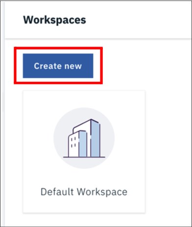
Figure 6-349 Create new workspace
7. We need to give the workspace and name (IBM Redbooks) and if you like, upload a logo for the workspace (we have used the IBM Redbooks logo). You will also see the default node that the files will be stored in (do not change this). See Figure 6-350.

Figure 6-350 Redbooks workspace
8. Click the Applications tab and ensure that the Files and Packages are shown as active.
In the Packages app, a package (also called a digital package) is a collection of digital assets (such as files, folders, video, images). You gather them to send to one or more individuals or user groups, or to an Aspera on Cloud shared inbox. You can also attach files and folders in your Files app as you create a digital package in the Packages app. Simply right-click the items in your Files app to include in the package and select the option to send. You can add content to a package you initiate from the Files app. See Figure 6-351.
In our scenario we will be sending only a single file through the File application.

Figure 6-351 Applications
9. Now click the Settings tab. We will not be changing any of the settings but there is one here that we need to take notice of for later in the scenario. See Figure 6-352.

Figure 6-352 Settings
10. Click Email Settings and Templates. Notice that the Subject prefix is IBMAsperaOnCloud. This will come into play in the event flow part of the scenario. See Figure 6-353.

Figure 6-353 Email templates
11. Using the navigator, move to the Files application. Click the IBM Redbooks workspace. See Figure 6-354 on page 414.

Figure 6-354 Files and workspaces
12. We will create a folder to contain our files for transfer. Click Create Folder. Enter a name for the new folder (we chose forTransfer). See Figure 6-355.

Figure 6-355 New folder
We are now ready to upload the file and send it to the recipient.
Upload a file
Perform the following steps to upload a file:
1. Click New folder to open it.

Figure 6-356 Upload files
3. This will open a pop-up window (Figure 6-357 on page 416), where you can select the file to be transferred. Which file that you decide send in not important for this scenario, but a file of a decent size would be ideal.
|
Tip: If you are using a Mac, you may find that the window to select the file is in the background.
|

Figure 6-357 Select a file to upload
4. The upper right area of Figure 6-358 shows that there is one active transfer. (This is your upload.)

Figure 6-358 Active transfer
5. Click the Transfer icon to see the current progress of the upload.
We can see the activity of the upload by clicking the dotted box again and selecting Activity.
On this dashboard we see information about all of the transfer, but specifically the current transfer in progress.
Tabs on the left side of this dashboard provide good information for our scenario regarding volume usage and file access available. See Figure 6-359 on page 417.

Figure 6-359 Upload transfer activity
6. Go back to the Files application. Click the IBM Redbooks workspace and drill down to the current file to see the progress. After the file has been successfully uploaded, you can see the various options available for processing of this file. See Figure 6-360.

Figure 6-360 Options for the file
We are now ready to send the file to the intended recipient.
Send a file
If this scenario, we send the file to a Gmail address. We plan to use the Gmail application connector in IBM App Connect in the next part of the scenario.
If you want to build the second half of the scenario but do not have a Gmail account, get one now.
1. Using the options menu that was shown earlier, select Send.
A pop-up window will appear where the details of the file and recipient are to be entered.
2. Enter the Gmail address of the intended recipient, add a subject that will let the recipient know what has been sent. As shown in Figure 6-361 the file should already be listed there.
|
Tip: If you select the wrong file and the file is not the one you intended, simply remove that file (using the x) and drag and drop the correct file from the list of uploaded files.
|
3. Optionally, you can add a message for the recipient (in our scenario, we added a message to remind the recipient that the file is large). Part of the claim-check pattern means that the recipient is alerted to the arrival of the file (that is, they receive the claim check). However, it may not be the most suitable time for them to download such a large file. They may want to process the file at a more appropriate time.
4. Additionally, you can choose to password protect the file (if it contains sensitive information) and request that someone is notified if the package is available and/or downloaded). These are in the Options section, but we will not be using them for our scenario.

Figure 6-361 Send the file
5. Click Send.
6. If we now view the Activity monitor again (via the indicator in the upper section of the screen), we see that the file transfer is being processed. See Figure 6-362 on page 419.

Figure 6-362 File transfer being processed
When the transfer has been completed, we will see an email in the inbox of the recipient.
6.13.2 Build an event-driven flow
In this part of the scenario we will be using IBM App Connect. For many people, simply going and reading email periodically may be a standard way to work. However, as you build out your new digital infrastructure to respond to ever-changing customer demands, you need to be able to capture new events, contextually and in near real time. By orchestrating the right follow on actions through workflows, you immediately react to new events. In this way, you ensure that your customers and employees have a positive experience.
IBM App Connect allows you to utilize smart connectors to capture events from your systems designed on event-driven architectures. Unique capability and situational tooling then empowers your teams that have the context to apply such data. These teams can rapidly build and change integrations as their needs shift, enabling the business to move at the speed of its customers.
Imagine that the file that we sent in 6.13.1, “Build the file transfer” on page 410 was an urgent file that is required to resolve a customer situation. It would be ideal if the customer service representative could automatically be alerted to the fact that the file has arrived and could immediately take respond.
Sign up for a free trial
In this part of the scenario we will be utilizing two of the smart connectors in IBM App Connect. As you will have read previously, there are over 100 to choose from.
If you have not already done so, sign-up for a free trial on the IBM Cloud.
In 6.13.1, “Build the file transfer” on page 410, you signed up for a Gmail account. You also need to sign up for a Slack trial account if you do not already have one.
Slack is a collaboration hub where you and your team can work together to get things done.
You can sign-up for a trial account here:
You will need to define the following elements:
•Slack workspace:
A workspace is a shared hub made up of channels, where team members can communicate and work together.
A workspace is a shared hub made up of channels, where team members can communicate and work together.
•Slack channel:
In Slack, work happens in channels. You can create channels based on teams, projects or even office locations. Members of a workspace can join and leave channels as needed. You can create a channel that has you as the only member, for receiving your file notifications.
In Slack, work happens in channels. You can create channels based on teams, projects or even office locations. Members of a workspace can join and leave channels as needed. You can create a channel that has you as the only member, for receiving your file notifications.
•Slack application:
Apps and integrations are the tools that will help you to bring your existing workflows into Slack.
Apps and integrations are the tools that will help you to bring your existing workflows into Slack.
The Slack App Directory has thousands of apps that you can integrate into Slack. See Figure 6-363.
IBM App Connect is one of these apps. Instructions to create the app can be found at:

Figure 6-363 Integration into Slack
After you have your Gmail, Slack and IBM App Connect service on the IBM Cloud, we are ready to build the event-driven flow.
Build the flow
Perform the following steps to build the flow:
1. Log on to the IBM App Connect service on the IBM Cloud.
To enable IBM App Connect to interact with the applications (Gmail and Slack) you need to first connect your credentials for these accounts. (This can also potentially be done as you build the flow, but it is easier to get it out the road up front).
2. Go to the Catalog tab and select Applications. Here you can either scroll down to find the Gmail application or type in a filter for it. See Figure 6-364 on page 421.

Figure 6-364 Connect Gmail
3. Click Connect, follow the instruction to log on to Google (if you are not already logged on). See Figure 6-365.

Figure 6-365 Connect account
4. Allow IBM App Connect access to your Gmail account.
After this has been completed, you will see a pop-up message that your account is connected and you can check the details. See Figure 6-366 on page 422.

Figure 6-366 Connected Gmail account
5. Repeat the procedure for your Slack information, and agree to connect. See Figure 6-367.

Figure 6-367 Connect Slack
6. You will, again, receive a pop-up indicating that your account is connected. See Figure 6-368 on page 423.

Figure 6-368 Slack account connected
7. Click to go back to the Dashboard.
As we mentioned, we will be building an event-driven flow. That is, a flow that kicks off in response to something noteworthy happening in an application.

Figure 6-369 New event-driven flow
9. A pop-up will appear for us to build the flow. First, you add the application where the event occurs (in this case, the event is the arrival of an email).

Figure 6-370 How do you want to start the flow
11. We need to select the Account (you may have only one Gmail account connected, so it will default to this account) and the application event (in this case, it is the arrival of a new email).

Figure 6-371 Configure event parameters
12. We then need to define what happens next after the event has been detected and received. In this case, simply putting a message to Slack is a good start.
13. Click on the blue circle and select Application. After the event has been received, you may choose to do any number of other before passing on to the destination application things. For example, you could invoke an API or use any of the utilities in the toolbox to manipulate or filter the data. More on this later.
14. Select the Slack application. We now see the various operations that can be performed in Slack. In this scenarios, we will be creating a message that is sent to Slack. See Figure 6-372.

Figure 6-372 Create message in Slack
We now have the source event application and the target application in the flow as shown in Figure 6-373.

Figure 6-373 Applications
We could run this flow by providing only one additional configuration detail:
What is the message that we want to post to Slack?
What is the message that we want to post to Slack?
15. Click the Slack application in the flow. In the lower half of the screen, the parameters for the application are shown in Figure 6-374 on page 426.
The one mandatory piece of configuration that is missing is the text (the message).

Figure 6-374 What’s the message?
16. Click the blue icon next to the field to show all inputs that are available for the text. One of the nice design features about IBM App Connect is that at any point in a flow, all data of any operation or application that has come before is available for use. In this case, we have only the email itself, so we see a list of all of the parts of the email.
17. Select the Body from the list.

Figure 6-375 Insert Body
Now, the flow is correct and complete, and we could stop here and start the flow. However, not all emails to that account are necessarily file transfer notifications, so we need to filter out anything not relevant.
18. Click the + sign between the two applications. Select the Toolbox in the pop-up that appears. Here we see many different things that we light want to do with the data we are processing (conditional logic, array handling, parsing and so on).
19. In this scenario we can use the conditional If tool. Click this tool. See Figure 6-376 on page 427.

Figure 6-376 Add conditional logic
20. An If block appears in the flow. You can ignore the error flag as this simply indicates that there is more configuration required. See Figure 6-377.

Figure 6-377 If block
The one mandatory piece of configuration we need to add is the if condition. This is shown in Figure 6-378 on page 427.

Figure 6-378 Needs an if condition
You might recall that earlier in this section (step 10), we took note of the default Subject prefix that would be put on the email to the recipient. We will now filter to only process emails that contain that prefix. For this we need to use a $contains() string function.
21. In the if condition box, type co.
22. This will pop-up an auto-complete helper, where we see String functions. Open the list and select the $contains() function. See Figure 6-379.

Figure 6-379 Select the function
23. We now see that the function has been inserted into the condition, we merely have to complete it. Before we do that, use the drop-down list to change the condition from is equal to is true.
24. Click the string and use the blue box at the side of the condition to pop up the available input. This time, select the Subject of the email. See Figure 6-380 on page 428.

Figure 6-380 Fill condition
25. We now need to fill the character string to match, this is “[IBMAsperaOnCloud]”. Simply position the cursor after the double quotation marks, and enter the text as shown in Figure 6-381.

Figure 6-381 Completed condition
We need to move the call to Slack from outside the If block to inside so that we send only a message to Slack for the relevant emails.
26. Drag the Slack application from outside the IF block to inside as shown in Figure 6-382 on page 429.

Figure 6-382 Completed flow
27. Last but not least, give the flow a meaningful name (we chose Notification from Aspera). See Figure 6-383.

Figure 6-383 Flow name
28. If everything has been done correctly, we see a pop-up indicating that the flow is ready to be started (for example ready to start receiving and processing events). See Figure 6-384.

Figure 6-384 Congratulations, flow complete
The flow can be started either from here or from the main Dashboard.
29. Go back to the Dashboard. Right click the hamburger menu and select Start. See Figure 6-385 on page 430.

Figure 6-385 Start flow
We are now ready to test the flow.
Test the flow by sending another file
Perform the following steps for testing the flow:
1. Go back to IBM Aspera on Cloud and repeat the file transfer that you performed before.
2. After the transfer has completed, go back to the IBM App Connect dashboard.
3. If the flow has successfully received the event notification from Gmail and processed it, you will see a green tick in the lower right of the tile for the flow. See Figure 6-386.

Figure 6-386 Successful completion
4. You should also see a notification from Slack that a message has been received. Open the message received. We see that IBM App Connect has given us the details of the email and also a link (containing a token) which is our claim check. Thus, allowing the recipient to download the file when it makes sense to do so, and without having to have an IBM Aspera account or IBM Aspera transfer server. See Figure 6-387 on page 431.

Figure 6-387 Go and get the file
We could further refine this scenario but adding or removing some of the information from the email body using the toolbox in IBM App Connect. We could also have processed the file, which would potentially make sense for a small file. However, the claim check pattern enables us to deal with much larger files in an “offline” fashion rather than blocking our fast-moving messaging platforms.
Obviously, this is a very simplistic scenario and only scratches the surface of what you can do with IBM Aspera on Cloud. For more information, go to this web site:
..................Content has been hidden....................
You can't read the all page of ebook, please click here login for view all page.