
Chapter 8. IOS Switches
This chapter covers the following subjects:
• IEEE 802.1X, Extensible Authentication Protocol (EAP) and EAP over LANs (EAPOL)
• Different Types of EAP Available
• Configuration Examples Based on Some EAP Types Available for ACS 4.2 and ACS 5.1
This chapter examines the IEEE 802.1X standard and the components involved in it that can be used to secure the LAN or wireless LAN (WLAN) infrastructure. The chapter essentially examines Layer 2 security and how Access Control Server (ACS) will help secure the LAN and WLAN infrastructure. This chapter focuses on LAN infrastructure, as Chapter 9, “Access Points,” focuses on the WLAN infrastructure.
Introduction to IEEE 802.1X, EAP, and EAPOL
802.1X is an IEEE standard for media-level access control, offering the capability to permit or deny network connectivity, control VLAN access, and apply traffic policy, based on user or machine identity. The basic idea behind the standard is to authenticate and authorize before a user can connect to the physical or logical port of a Layer 2 device in order to gain access to VLAN or WLAN infrastructure.
The IEEE IEEE 802.1X restricts unauthorized clients from connecting to the LAN or WLAN infrastructure by using a client and server-based access control and authentication protocol.
The IEEE 802.1X standard defines three main entities that take part in the access control method set up in this standard:
• Client or Supplicant: The device that needs access or requests access to the LAN/WLAN infrastructure or Layer 2 device services. The device must be running IEEE 802.1X-compliant client software so that it can respond to requests from a Layer 2 device.
• Authenticator: The device responsible for relaying information between the authentication server and the supplicant. The authenticator is a Layer 2 device that acts as an intermediary or proxy between the client and the authentication server, by requesting identity information from the client, verifying that information with the authentication server, and replaying the response returned by the authentication server to the client or supplicant.
• Authentication Server: The device responsible for performing actual authentication and authorization on behalf of the authenticator. The authentication server validates the identity of the client or supplicant and notifies the Layer 2 device acting as authenticator, which relays information to the client. For the purposes of this chapter, the authentication server would be Cisco Secure ACS and the protocol would be RADIUS.
Figure 8-1 provides an overview based on the different roles.
Figure 8-1. IEEE 802.1X Device Roles

Figure 8-2 provides a more generic overview of the IEEE 802.1X architecture.
Figure 8-2. IEEE 802.1X Architecture
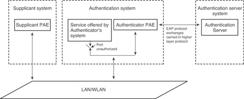
The port access entity (PAE) specified in Figure 8-2 refers to the entity on a given device that performs the IEEE 802.1X algorithm and protocol operation.
Now that you have a general overview of IEEE 802.1X, the text that follows delves into this standard a little deeper and examines and how it works.
Extensible Authentication Protocol (EAP) is the key protocol used to pass the authentication information between the supplicant and the authentication server.
IEEE IEEE 802.1X defines encapsulation of EAP over IEEE 802 and is known as EAP over LANs (EAPOL). EAPOL was originally designed for Ethernet but was extended to suit other technologies such as wireless and Fiber Distribution Data Interface (FDDI).
EAP is an authentication framework, not a specific authentication mechanism. It provides some common functions and negotiation of authentication methods called EAP methods. EAP methods support different authentication types, such as token cards, one-time passwords, certificates, and public key authentication.
The sections that follow look at EAP and EAPOL so that you understand them better before proceeding any further.
EAP
EAP is an authentication framework that supports multiple authentication methods. Basically, EAP allows two entities to exchange information that is specific to the authentication method these entities want to use. The content of these authentication specific methods is not defined in EAP.
This is one of the advantages offered by the EAP architecture—its flexibility. The authenticator need not be updated to support different or new authentication methods—only the client/supplicant and the authentication server can implement some of or all the authentication methods.
Today, there are many authentication methods or EAP authentication methods available, some of which are defined in the IETF RFCs (EAP-MD5, EAP-OTP, EAP-GTC, EAP-TLS, and more) and some of which are vendor-specific methods (PEAP, LEAP, EAP-TTLS).
EAP specifies that four types of messages can be sent:
• Request(0x01): Used to send messages from the authenticator to the supplicant
• Response(0x02): Used to send messages from the supplicant to the authenticator
• Success(0x03): Sent by the authenticator to indicate access is granted
• Failure(0x04): Sent by the authenticator to indicate access is refused
Figure 8-3 illustrates the EAP message format and the list that follows describes each of the fields.
• Code: The one-byte Code field indicates the type of message (Request, Response, Success or Failure).
• Identifier: The one-byte Identifier field contains an unsigned integer used to match requests with responses. Each new request uses a new identifier number.
• Length: The two-byte Length field indicates the total number of bytes in the entire packet.
• Data: The value of the variable-length (including zero byte) Data field defines the way the Data field is to be interpreted.
Figure 8-3. EAP Message Format
![]()
The EAP message format shown in Figure 8-3 is used to send
• EAP Request
• EAP Response
• EAP Success
• EAP Failure
For the EAP Request and EAP Response, one more field is introduced: the Type field, as illustrated in Figure 8-4. The one-byte Type field defines the type of request or response. Only one Type is used in each packet and the response Type matches the request.
Figure 8-4. EAP Request/Response Message
![]()
For EAP Success and EAP Failure, the Data field is of zero bytes in length. The rest of the structure remains the same as shown previously in Figure 8-3.
As previously stated, the EAP Request and EAP Response messages are subdivided using the EAP Type field. Some common EAP types are as follows:
• Identity (1)
• Notification (2)
• NAK (3)
• MD5-Challenge (4)
• One-Time Password (OTP) (5)
• Generic Token Card (6)
• EAP-TLS (13)
• EAP-TTLS (21)
• PEAP (25)
• EAP-FAST (43)
The most important predefined Type is Identity (Type = 1) because this is used as a part of the EAP introduction phase:
• EAP-Request/Identity (Code = 1, Type = 1): Sent by authenticator to a new supplicant.
• EAP-Response/Identity (Code = 2, Type = 1): In response to EAP-Request/Identity, supplicant replies with this message containing its username or some other identifier that will be understood by the authentication server.
For details on other EAP types, please refer to the EAP RFC (RFC 2284). For other EAP types or methods, you need to refer to individual RFCs or drafts.
The section that follows looks at EAPOL to continue the discussion on IEEE 802.1X.
EAPOL
The EAP RFC does not specify how messages should be communicated. So, to communicate EAP messages, you need to find a way to encapsulate them. To solve this puzzle, IEEE IEEE 802.1X defined a protocol called EAP over LAN (EAPOL) to get EAP messages to be communicated between the supplicant and the authenticator. EAPOL was originally designed for Ethernet but was extended to suit other technologies.
Figure 8-5 illustrates the frame format for EAPOL frames.
Figure 8-5. EAPOL Frame Format
![]()
The five types of EAPOL messages are as follows:
• EAPOL-Packet (0): Contains an encapsulated EAP frame. This is what the majority of EAPOL frames are.
• EAPOL-Start (1): A supplicant can send an EAPOL-Start frame instead of waiting for a challenge from the authenticator (EAPOL-Packet [EAP-Identity/Request]).
• EAPOL-Logoff (2): Used to return the state of the port to unauthorized when the supplicant has finished using the network.
• EAPOL-Key (3): Used to exchange cryptographic keying information.
• EAPOL-Encapsulated-ASF-Alert (4): Provided as a method of allowing Alerting Standards Forum (ASF) alerts to be forwarded through a port that is in the unauthorized state.
Message Exchange in IEEE 802.1X
Now you know what EAP and EAPOL are, it’s time to return to the general discussion of IEEE 802.1X. As discussed previously, there are three entities in IEEE 802.1X: supplicant, authenticator, and authentication server. Messages are exchanged among these three entities. IEEE 802.1X uses EAP, or more specifically EAPOL, to pass these messages between supplicant and authenticator and between authenticator and authentication server using RADIUS by encapsulating EAP in RADIUS, sometimes referred to as EAP over RADIUS.
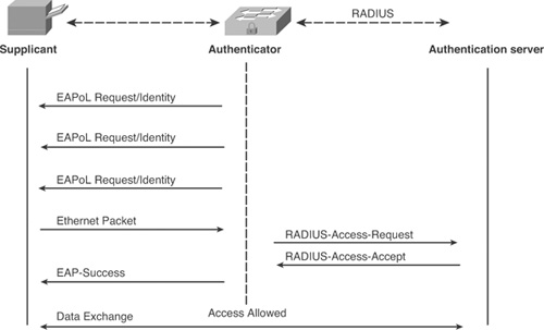
Figure 8-6 illustrates a typical EAPOL/802.1X exchange.
Figure 8-6. EAPOL/802.1X Message Exchange
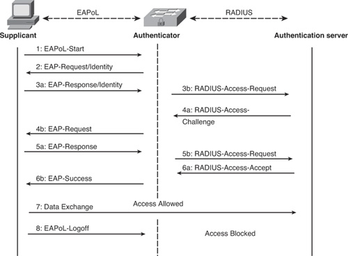
The operation process in IEEE 802.1X is as follows:
Step 1. Generally, the authenticator sends the first EAP-Request message of the identity type to the supplicant to ask for the supplicant’s identity. The supplicant can also start this process if it so desires by sending EAPOL-Start.
Step 2. If the supplicant sends EAPOL-Start, the authenticator requests the supplicant’s identity by sending EAP-Request/Identity.
Step 3. In response, the client sends its information in EAP-Response/Identity frame. The supplicant decapsulates the information from the EAPOL frame and passes over the EAP information in it to the authentication server using the RADIUS protocol as RADIUS-Access-Request.
Step 4. The RADIUS server negotiates with the supplicant by sending RADIUS-Access-Challenge to the authenticator, which encapsulates the EAP information in an EAPOL frame and passes it over to the supplicant as EAP-Request.
Step 5. In response to EAP-Request, the supplicant sends back EAP-Response over to the authenticator, that again decapsulates the EAP information and sends it to the authentication server using RADIUS-Access-Request.
Step 6. There are several exchanges of EAP-Response/RADIUS-Access-Request and RADIUS-Access-Challenge/EAP-Request before finally the RADIUS server sends RADIUS-Access-Accept, which signifies that user was authenticated. When this response is received by the authenticator, the authenticator decapsulates the EAP information and sends it to the supplicant as EAP-Success. At this point, the port is authorized and the supplicant is allowed to communicate.
Step 7. At this stage, the supplicant can proceed with data exchange.
Step 8. After data exchange has finished and the supplicant leaves the access port, it sends EAPOL-Logoff to the authenticator to let it know that it has left the port and it can now be brought back to the blocked or unauthorized state.
EAP Types
The previous section explained that the EAP-Request/Response identity frame has a field called Type. This field has various values that also help in deciding what EAP authentication method to use after it is negotiated between the supplicant and the authentication server.
A few of the different EAP authentication types available are as follows:
• EAP-MD5: EAP-MD5 (Message Digest) Challenge is an EAP authentication type defined in RFC 3748. It offers minimal security. It is typically not recommended because it might allow the user’s password to be compromised because the MD5 hash function is vulnerable to dictionary attacks. In this EAP authentication type, there is only one-way authentication; there is no mutual authentication between EAP peer and EAP server. Because it provides authentication only of the EAP peer to the EAP server and does not provide EAP server authentication, this EAP authentication method is also vulnerable to man-in-the-middle attacks.
• LEAP: Lightweight Extensible Authentication Protocol (LEAP) is a proprietary EAP authentication type developed by Cisco Systems. This is primarily used in Cisco WLANs. This protocol was distributed through the Cisco Certified Extensions (CCX) as part of getting IEEE 802.1X and dynamic Wired Equivalent Privacy (WEP) adoption, in the absence of a security standard in industry. LEAP encrypts data transmissions using dynamically generated WEP keys. It also supports mutual authentication. Although LEAP supports mutual authentication, user credentials can still be easily compromised. Recommended practice dictates that if you must use LEAP, this should be done only with sufficiently complex passwords.
• PEAP: Protected Extensible Authentication Protocol (PEAP) is jointly developed by Cisco Systems, Microsoft, and RSA Security. This EAP authentication method allows for secure transport of authentication data, thus providing very good security. This is accomplished by creating a tunnel between PEAP clients and an authentication server. In PEAP, only a server-side public key infrastructure (PKI) certificate is required to create a secure Transport Layer Security (TLS) tunnel to protect user authentication. The requirement to have only a server-side certificate simplifies the implementation and administration of secure LAN/WLAN.
There are two certified PEAP subtypes available:
• PEAPv0/EAP-MSCHAPv2
• PEAPv1/EAP-GTC
Note
The terms PEAPv0 and PEAPv1 refer to the outer authentication method—the mechanism that creates the secure TLS tunnel to protect subsequent authentication transactions. EAP-MSCHAPv2 and EAP-GTC refer to the inner authentication method, which facilitates user or device authentication.
• EAP-TLS: EAP-TLS (Transport Layer Security) is defined in RFC 5216. The security offered by the TLS protocol is strong because it provides certificate-based and mutual authentication. It uses PKI to secure communication to an authentication server. As opposed to PEAP, EAP-TLS has more administrative overhead because it requires client-side certificates along with a server-side certificate to perform authentication. The reason EAP-TLS is considered one of the most secure EAP authentication types is that even if a password is compromised, it is not enough to break into EAP-TLS–enabled systems because the hacker still needs to have the client-side private key. Security provided by EAP-TLS can be made more secure if you introduce smart cards because in smart cards the client-side keys are housed on the card itself. In the event of the theft of a smart card, it is much more likely to be noticed than password theft, which makes recognizing the potential for a security break much easier to mitigate by simply revoking the smart card.
• EAP-FAST: EAP-FAST (Flexible Authentication via Secure Tunneling) is defined in RFC 4851 and was developed by Cisco Systems. The protocol was designed to address the weaknesses of LEAP while preserving the lightweight implementation. Instead of using a certificate, mutual authentication is achieved by means of a Protected Access Credential (PAC). A PAC file is issued on a per-user basis, which can be managed dynamically by the authentication server. EAP-FAST uses PAC to establish a TLS tunnel in which client credentials are verified. The PAC can be provisioned to the client either manually or automatically. Manual provisioning is delivered to the client via disk or a secured network distribution method. Automatic provisioning is an in-band distribution.
• Phase 0: An optional phase in which the PAC can be provisioned manually or dynamically.
• Phase 1: In this phase, the client and the authentication server uses the PAC to establish TLS tunnel.
• Phase 2: In this phase, the client credentials are exchanged inside the encrypted tunnel.
EAP-FAST can also be used without PAC files using certificate-based mutual authentication as in TLS.
Tip
When automatic PAC provisioning is enabled, EAP-FAST has a slight vulnerability in that an attacker can intercept the PAC and subsequently use it to compromise user credentials. This vulnerability is mitigated by manual PAC provisioning or by using server certificates for the PAC provisioning phase (Phase 0).
PEAPv0/EAP-MSCHAPv2
PEAPv0/EAP-MSCHAPv2 is commonly known as “PEAP.” After EAP-TLS, PEAPv0/EAP-MSCHAPv2 is the second most widely supported EAP standard in the world. PEAPv0/EAP-MSCHAPv2 is natively supported in many operating systems. This version of PEAP was defined in Internet draft “draft-kamath-pppext-peapv0.”
The support for inner EAP methods in PEAPv0 varies from vendor to vendor. Other known forms of PEAPv0 are PEAPv0/EAP-SIM and PEAPv0/EAP-TLS (PEAP-EAP-TLS).
PEAP-EAP-TLS require a client-side digital certificate located on the client’s hard drive or a smart card. PEAP-EAP-TLS is very similar in operation to EAP-TLS, but provides slightly more protection due to the fact that portions of the client certificate that are unencrypted in EAP-TLS are encrypted in PEAP-EAP-TLS.
PEAPv1/EAP-GTC
PEAPv1/EAP-GTC was created by Cisco as an alternative to PEAPv0/EAP-MSCHAPv2. It allows the use of an inner authentication protocol other than Microsoft’s MSCHAPv2.
EAP-GTC (Generic Token Card) is defined in RFC 3748. It carries a text challenge from the authentication server, and a reply that is assumed to be generated by a security token.
This version of PEAP is defined in the IETF internet draft “draft-josefsson-pppext-eap-tls-eap-10.”
Note
To use PEAPv0/EAP-MSCHAPv2 or PEAPv0/EAP-GTC, you must ensure that both client and server support it.
EAP Authentication Type Summary
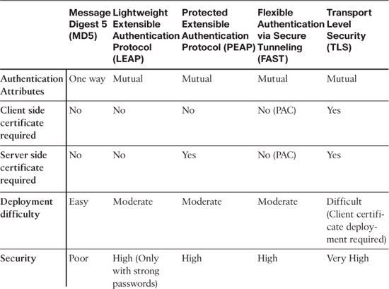
Table 8-1 summarizes the key features of the various EAP authentication types described up to this point in the chapter.
Table 8-1. Comparison of EAP Authentication Types
What you have learned so far is very generic, vendor-neutral IEEE 802.1X learning. The rest of the chapter focuses on Cisco switch-based IEEE 802.1X configuration.
802.1X Configuration on a Cisco Switch
To enable IEEE 802.1X port-based authentication, you need to perform following tasks:
Note
Earlier IEEE 802.1X commands on Cisco IOS are being replaced by authentication manager commands, but they provide the same functionality as earlier IEEE 802.1X commands. The authentication manager commands were introduced in Cisco IOS Software Release 12.2(50)SE & 12.2(50)SG as you will find here:
Step 1. Enable AAA on the switch:
Device(config)# aaa new-model
Step 2. Configure the switch for RADIUS server communication:
Device(config)# radius-server host {hostname| ip_address}
Device(config)# radius-server key string
Step 3. Create an IEEE 802.1X port-based authentication and authorization method list:
Device(config)# aaa authentication dot1x default method1 [method2...]
Device(config)# aaa authorization network default method1 [method2...
Step 4. Globally enable IEEE 802.1X port-based authentication:
Device(config)# dot1x system-auth-control
Step 5. Enter the interface configuration mode for the specific interface:
Device(config)# interface type slot/port
Step 6. Set the port to access mode:
Device(config-if)# switchport mode access
Step 7. Enable port-based authentications on the interface:
New commands:
Device(config-if)# authentication port-control auto
Device(config-if)# dot1x pae authenticator
Old command:
Device(config-if)# dot1x port-control auto
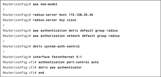
Example 8-1 shows the full basic IEEE 802.1X configuration on a Cisco IOS switch.
Example 8-1. Basic IEEE 802.1X Configuration on a Cisco IOS Switch
Note
The IEEE 802.1X protocol is supported on Layer 2 static-access ports, voice VLAN ports, and Layer 3 routed ports, but it is not supported on trunk port, dynamic ports, dynamic access ports, EtherChannel ports, Switch Port Analyzer (SPAN) or Remote SPAN (RSPAN) destination ports.
Note
When IEEE 802.1X is enabled on a switchport, until a supplicant is authenticated, the switchport remains in the unauthorized state. In this unauthorized state, only EAPOL traffic is allowed to pass and all other traffic is dropped. On Cisco switches along with EAPOL, CDP/LDP is also allowed.
802.1X Host Modes
Host mode on an IEEE 802.1X-enabled port decides whether to allow only one client to authenticate (which is there by default) or to allow multiple clients or some other special condition.
There are four host modes available and one mode that are applied with all other four modes.
The four host modes are as follows:
• Multidomain authentication mode
Pre-authentication open access is the mode that is applied with the other four modes. The sections that follow describe these modes in more detail and how to configure them.
Single-Host Mode
In this mode, only one client can be connected to an IEEE 802.1X-enabled port. The commands to configure this mode are as follows.
Note
Earlier IEEE 802.1X commands on Cisco IOS are being replaced by authentication manager commands, but they provide the same functionality as earlier IEEE 802.1X commands. The authentication manager commands were introduced in Cisco IOS Software Release 12.2(50)SE & 12.2(50)SG, the information for which you can find here:
For Cisco IOS switches, the new command to configure this mode is as follows:
Router(config-if)# authentication host-mode single-host
For Cisco IOS switches, the old command to configure this mode is as follows:
Router(config-if)# dot1x host-mode single-host
Multiple-Host Mode
In this mode you can attach multiple clients to the IEEE 802.1X-enabled port. The feature of this mode is that only one client must be authorized for all clients to grant network access. The commands to configure this mode are as follows.
For Cisco IOS switches, the new command to configure this mode is as follows:
Router(config-if)# authentication host-mode multi-host
For Cisco IOS switches, the old command to configure this mode is as follows:
Router(config-if)# dot1x host-mode multi-host
Multidomain Authentication Mode
In this mode, also known as Multidomain Authentication (MDA) mode, an IP Phone and a single host behind the IP Phone are authenticated independently, even though both the IP Phone and host machine are connected to a single switch port on the switch. Multidomain in this mode refers to two domains:
• Data domain
• Voice domain
Only two MAC addresses are allowed on a port where MDA is enabled. The switch can place the client machine in a data VLAN and the IP Phone in a voice VLAN, even though they appear on the same switch port. The commands to configure this mode are as follows.
For Cisco IOS switches, the command to configure this mode is as follows:
Router(config-if)# authentication host-mode multi-domain
Note
To authorize a voice device, the AAA server must be configured to send a Cisco Attribute-Value (AV) pair attribute with a value of device-traffic-class=voice. Without this value, the switch treats the voice device as a data device.
Multiauthentication Mode
Also known as multiauth mode, this mode allows for one IEEE 802.1X client on a voice VLAN and multiple authenticated IEEE 802.1X clients on a data VLAN. In multiauth mode, each client connected needs to be authenticated individually; this is the main difference between multiple-host mode and multiauth mode.
For Cisco IOS switches, the command to configure this mode is as follows:
Router(config-if)# authentication host-mode multi-auth
Note
When a switchport is in multiauth mode, VLAN assignment through a RADIUS server, guest VLAN and authentication fail, and VLAN features do not activate.
Pre-Authentication Open Access
The pre-authentication open access mode, which can be used with the four host modes, allows a device to gain network access before authentication. This is useful to test IEEE 802.1X functionality; it is like a pilot feature that is turned off after the administrator is comfortable with the IEEE 802.1X deployment. Whenever this is applied on a switchport, it is always recommended that you should use static ACLs to restrict Layer 3 traffic. Pre-authentication open access can be configured additionally with any of the four host modes.
To configure pre-authentication open access on Cisco IOS switches, use the following command:
Router(config-if)# authentication open
Note
Please refer to prerequisites and expected behavior for a platform/Cisco IOS version for IEEE 802.1X host modes. The operation might differ by platform/version.
802.1X Authentication Features
The authentication features available on Cisco IOS with IEEE 802.1X are as follows:
• Inaccessible Authentication Bypass
• ACL Assignment and Redirect URLs
And many more. To get detail on which feature does what, and how already existing feature co-exists with IEEE 802.1X, please refer to the IEEE 802.1X section in the configuration guide of the respective switch platform and IOS/Catalyst OS.
We will look at few features in this section. Namely, Guest VLAN, Restricted VLAN, MAC Authentication Bypass, and VLAN Assignment.
Guest VLAN
To provide limited services to non-802.1X-compliant clients, you can make use of the guest VLAN feature. When you enable guest VLAN on an IEEE 802.1X port, the switch assigns clients to a guest VLAN when the switch does not receive a response to its EAP request/identity frame or when EAPOL packets are not sent by the client and no fallback authentication methods are enabled.
By default, the switch maintains the EAPOL packet history. If an EAPOL packet is detected on the interface during the lifetime of the link, the switch determines that the device connected to that interface is an IEEE 802.1X-capable supplicant, and the interface will not change to the guest VLAN state. The EAPOL packet history is cleared if the interface link status goes down.
If you want the interface to change to the guest VLAN state for a non-802.1X-capable client, regardless of the EAPOL packet history, use the following global configuration command:
Switch(config)# dot1x guest-vlan supplicant
To configure a guest VLAN, the new command on a Cisco IOS switch is as follows:
Router(config-if)# authentication event no-response action authorize vlan vlan-id
To configure a guest VLAN, the old command on a Cisco IOS switch is as follows:
Router(config-if)# dot1x guest-vlan vlan-id
Restricted/Authentication Failed VLAN
If you want to provide limited service to clients who fail authentication, you can configure a restricted VLAN or an authentication failed VLAN. One thing that you need to note is that these clients are IEEE 802.1X compliant, so they cannot be assigned to the guest VLAN.
You can configure a port to be in a restricted VLAN after a specified number of failed authentication attempts. The switch counts the failed authentication attempts, with the failed attempt count incrementing when the RADIUS server replies with an Access-Reject EAP failure or an empty response without an EAP packet. When this count exceeds the configured maximum number of authentication attempts, the port is assigned to the restricted VLAN. After a port is moved to the restricted VLAN, the failed attempt counter for the port is reset and EAPOL-Start messages from the client are ignored.
Note
You can configure a VLAN to be both the guest VLAN and the restricted VLAN if you want to provide the same services to both types of users.
To configure a restricted VLAN, the new command on a Cisco IOS switch is as follows:
Router(config-if)# authentication event fail [retry retries] action authorize vlan vlan-id
The default retries value is 2 and is configurable from 1 to 5.
To configure a restricted VLAN, the old commands on a Cisco IOS switch are as follows:
Router(config-if)# dot1x auth-fail vlan vlan-id
Router(config-if)# dot1x auth-fail max-attempts max-attempts
The default max-attempts value is 3 and is configurable from 1 to 3.
After three failed authentication attempts, the supplicant is moved to a restricted or authentication fail VLAN.
Note
For configuration guidelines and restrictions, please refer to the device documentation section for IEEE 802.1X configuration because guidelines and restrictions can differ for IOS version and/or device platform:
MAC Authentication Bypass
You can now even configure a switch to allow clients based on their MAC addresses by using the MAC Authentication Bypass (MAB) feature. This can be useful in scenarios where IEEE 802.1X authentication times out while waiting for an EAPOL response from the client connected to the port, in which case the switch will try to authorize the client by using MAB. Devices such as printers, fax machines, and so on fall under this category.
When this feature is enabled, the switch uses the MAC address as the client identity. For this to be successful, the authentication server must have a database of allowed client MAC addresses.
After a client is detected on the port, the switch waits for an Ethernet frame from the client. The switch then sends the authentication server a RADIUS-access/request as illustrated in Figure 8-7.
Figure 8-7. MAC Authentication Bypass (MAB)
To configure MAB on a Cisco IOS switch, the new command is as follows:
Router(config-if)# mab [eap]
To configure MAB on a Cisco IOS switch, the old command is as follows:
Router(config-if)# dot1x mac-auth-bypass [eap]
Note
The eap keyword tells MAB to use the EAP protocol (inside of RADIUS) for the authentication, instead of just sending the MAC address as the username/password.
VLAN Assignment
If you want to specify a VLAN to which a user should be assigned after successful IEEE 802.1X authentication, you can do this with VLAN assignment feature. The RADIUS server database can be configured to maintain username-to-VLAN mapping. During authentication, the RADIUS server can send VLAN assignment information to the switch so that a user can be assigned to a RADIUS server–defined VLAN.
The VLAN assignment feature is automatically enabled when you configure IEEE 802.1X authentication on an access port. For VLAN assignment to work, you must ensure that network authorization is configured on the switch to allow interface configuration from the RADIUS server.
To configure the VLAN assignment feature on a Cisco IOS switch, enter the following command:
Switch(config)# aaa authorization network default method1 [method2...]
To configure the VLAN assignment feature on a Catalyst OS switch, no equivalent command exists, and none is required to turn this feature on.
The following RADIUS IETF attributes are configured in RADIUS server:
• [64] Tunnel-Type = VLAN
• [65] Tunnel-Medium-Type = 802
• [81] Tunnel-Private-Group-ID = VLAN name or VLAN ID
Note
The VLAN name or VLAN ID being specified in attribute 81 must exist on the switch configuration; otherwise, authorization will not work for VLAN assignment.
802.1X Timers
Configuring IEEE 802.1X configuration on a switch might not be sufficient enough to get it to work. You might be required to tweak a few IEEE 802.1X times to get it to work in an acceptable manner. There are different IEEE 802.1X timers available that can be tweaked to get the desired result. The sections that follow take a look at a few of these timers, including the following:
• Switch-to-client retransmission time
• Switch-to-client retransmission time for EAP-Request frames
• Switch-to-authentication-server retransmission time for Layer 4 packets
• Switch-to-client frame retransmission number
Quiet Period
When the switch cannot authenticate the client for some reason (for example, failed authentication), the switch remains idle for a set period of time and then tries again. The idle time is determined by the quiet-period value. The default is 60 seconds. This timer can be tweaked to provide a faster response.
To configure this timer on a Cisco IOS switch, enter the following command:
Router(config-if)# dot1x timeout quiet-period seconds
The value range for the seconds parameter is 0 to 65535 seconds.
Switch-to-Client Retransmission Time (tx-period)
The client responds to the EAP-request/identity frame from the switch with an EAP-response/identity frame. If the switch does not receive this response, it waits a set period of time, which is known as the retransmission time, and then retransmits the frame. You can tweak the amount of time that the switch waits for notification from 1 to 65535 seconds. The default is 30 seconds.
To configure this timer on a Cisco IOS switch, enter the following command:
Router(config)# dot1x timeout tx-period seconds
Switch-to-Client Retransmission Time for EAP-Request Frames (supp-timeout)
The client notifies the switch that it received the EAP-request frame. If the switch does not receive this notification, the switch waits a set period of time and then retransmits the frame. This timer can be tweaked to set the amount of time that the switch waits for notification from 1 to 65535 seconds. The default is 30 seconds.
To configure this timer on a Cisco IOS switch, enter the following command:
Router(config-if)# dot1x timeout supp-timeout seconds
Switch-to-Authentication-Server Retransmission Time for Layer 4 Packets (server-timeout)
The authentication server notifies the switch each time it receives a transport layer packet (Layer 4). When the switch does not receive a notification after sending a packet, it waits a set period of time and then retransmits the packet. This can be tweaked to set the amount of time that the switch waits for notification from 1 to 65535 seconds. The default is 30 seconds.
To configure this timer on a Cisco IOS switch, enter the following command:
Router(config-if)# dot1x timeout server-timeout seconds
Switch-to-Client Frame Retransmission Number (max-reauth-req)
The client notifies the switch that it received the EAP-request frame. If the switch does not receive this notification, the switch waits a set period of time, and then retransmits the frame. Apart from tweaking supp-timeout, we can tweak the number of times that the switch sends an EAP-request/identity frame to the client before restarting the authentication process from 1 to 10. The default is 2.
To configure this timer on a Cisco IOS switch, enter the following command:
Router(config-if)# dot1x max-reauth-req count
Configuring Accounting
Accounting is an essential part of the AAA architecture. An IEEE 802.1X accounting packet can indicate the following information to the RADIUS server:
• When a user successfully authenticates
• When a user logs off
• When the link goes down on an IEEE 802.1X port
• When a reauthentication succeeds
• When a reauthentication fails
There are three types of RADIUS accounting packets sent by a switch:
• START: Sent when a new user session starts.
• INTERIM: Sent during an existing session for updates.
• STOP: Sent when a session terminates.
To configure IEEE 802.1X accounting on a Cisco IOS switch, enter the following command:
Router(config)# aaa accounting dot1x default start-stop group radius
Certificate Installation on ACS
A certificate installed on an ACS server can be used for various purposes. A certificate can be used to secure an administrative session by enabling HTTPS (enabled by default in ACS 5.x) or to configure PEAP- or EAP-TLS-related authentications. The certificate installed on an ACS server is an identity certificate for a server. This section covers the steps required to install a certificate on an ACS server when you have an in-house Windows 2003 certificate authority.
On both ACS 4.2 & ACS 5.1, you have two options from which to install a certificate:
• Self-Signed Certificate: Certificate is issued to ACS server as an ACS server certificate. ACS cannot be used to issue certificate to any entity other than itself.
• External Certificate Authority: This includes any in-house or third-party certificate authority.
The self-signed certificate cannot be used for EAP-TLS authentication. The sections that follow show how to install a certificate using the external certificate authority.
The following checklist outlines the prerequisite items to install a certificate from an external certificate authority:
ACS Server certificate, which is issued by an external certificate authority
Certificate authority certificate
Intermediate certificate(s) authority certificate (only if certificate is issued to the ACS server from an intermediate certificate authority)
A note is provided to extract the private key file that is used to load the server certificate (identity certificate) for the ACS server. This is needed in situations where customers get a certificate with an embedded private key (.pfx file) from a third-party CA.
Certificate Installation on ACS 4.2
To install a certificate on ACS 4.2, perform the following steps:
Step 1. Go to System Configuration > ACS Certificate Setup > Generate Certificate Signing Request.
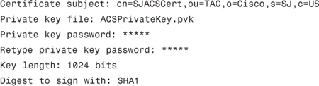
Step 2. Fill in the information for certificate signing request, that is: certificate subject, private key file, private key password, retype private key password, key length, digest to sign with.
For example:
Step 3. After filling the information, click Submit.
After clicking Submit, you will get the screen shown in Figure 8-8.
Figure 8-8. Certificate Signing Request on ACS 4.2
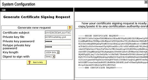
Copy the generated CSR (Certificate Signing Request) and save it in a notepad.
In certificate subject, CN (commonName) is the only mandatory field, the others can be skipped.
In ACS 4.2, you can specify the exact location of the private key file. For example:
Private key file: C:ACSACSPrivateKey.pvk
Tip
When using the ACS Solution Engine, only specify the filename in the Private key file field without specifying the file location.
Note
When obtaining a certificate from a third-party CA, it might provide you with a certificate that contains the identity certificate and the private key file. You need to convert the provided certificate into a format understandable by the ACS server. This can be done using OpenSSL toolkit:
openssl.exe pkcs12–in .pfx file name> -out <output filename.pem>
Password: Private key password
PEM Password: new password
confirm PEM Password: new password
This will generate a file that should be used on ACS for both the ACS certificate and the private key. The private key password will be the PEM password during file generation.
Step 1. Go to the certificate authority. In this example, you will access CA (Certificate Authority) using HTTP(S).
In the case of Windows 2003 CA, if configured to be accessible via HTTP, the CA can be accessed from
http(s)://<IP of Windows 2003 CA server>/certsrv
Access the CA server using the preceding URL and go to Request a certificate > advanced certificate request > Submit a certificate request by using a base-64-encoded CMC or PKCS #10 file, or submit a renewal request by using a base-64-encoded PKCS #7 file.
Paste the CSR obtained in step 3 under Saved Request and choose Web Server as the certificate template, and then click Submit as illustrated in Figure 8-9.
Figure 8-9. Certificate Generation Using CSR
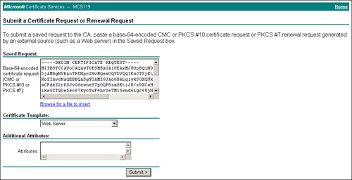
Download the certificate as Base 64–encoded. This will give us the ACS server certificate.
Now you also need a CA certificate, which you can download from the CA home page option Download a CA certificate, certificate chain, or CRL.
Download CA certificate as Base 64–encoded too.
Now you have two certificates.
Step 2. First install the CA certificate on ACS server from System Configuration > ACS Certificate Setup > ACS Certification Authority Setup.
Specify the location of the CA certificate and press Submit.
After the CA certificate is loaded, check it as a trusted certificate under System Configuration > ACS Certificate Setup > Edit Certificate Trust List.
Finally, install the ACS server certificate on the ACS server from System Configuration > ACS Certificate Setup > Install ACS Certificate.
Specify the location of the ACS server certificate and type the private key password.
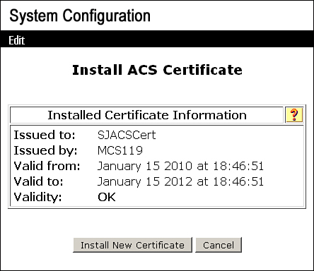
Now the ACS Server certificate will be installed as specified in Figure 8-10.
Figure 8-10. ACS Server Certificate
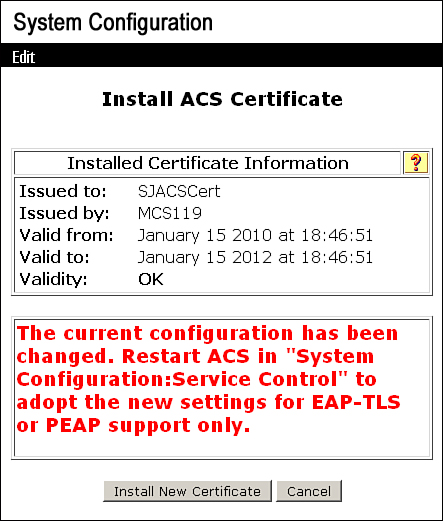
As mentioned in the message, to commit the changes on ACS, you need to go to System Configuration > Service Control and click Restart. After services are restarted, you will get the installed certificate as shown in Figure 8-11.
Figure 8-11. ACS Certificate Installed on ACS 4.2
Tip
With the ACS Solution Engine, if you plan to install the certificate by generating CSR from ACS SE, when specifying the location of ACS server certificate on FTP server, do not click on the link to specify the private key file location—only type the private key password after the ACS server certificate location has been specified on the FTP server.
Certificate Installation on ACS 5.1
As you already know, there are various ways of installing certificate on ACS, but this section focuses on installing a certificate using a CSR from an in-house Microsoft CA. To install certificate on ACS 5.1, you need to follow these steps:
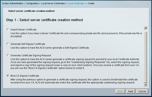
Step 1. Go to System Administration > Configuration > Local Server Certificates > Local Certificates > Add
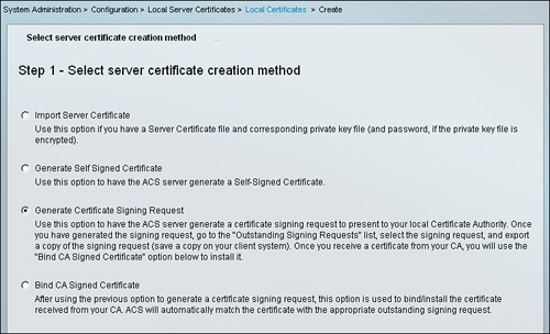
The wizard will provide four options from which to select to install a server certificate on ACS:
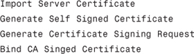
Each option has some descriptive text to explain what the option means. For demonstration purposes, the Generate Certificate Signing Request option is selected as illustrated in Figure 8-12. After selecting the option, click Next.
Figure 8-12. Select Server Certificate Creation Method
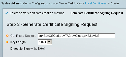
Step 2. In this section, you provide details for Certificate Subject and Key Length and click Finish. For demonstration purposes, the following information is filled in as illustrated in Figure 8-13:
Certificate Subject: cn=SJACSCert,ou=TAC,o=Cisco,s=SJ,c=US
Key Length: 1024
Figure 8-13. CSR Details
After clicking Finish, you get a message from the ACS server:
A server certificate signing request has been generated and can be viewed in the “Outstanding Signing Requests” list.
Step 3. Go to the section System Administration > Configuration > Local Server Certificates > Outstanding Signing Requests. In this section check the CSR that you created in the previous step and click Export as shown in Figure 8-14.
Figure 8-14. Downloading the CSR from ACS 5.1

This will prompt you to save the CSR in pem format.
Step 4. Open the downloaded pem file in WordPad or a similar text editor, and the CSR will appear similar to what you saw in the case of ACS 4.2 in Figure 8-8. Copy this request and follow step 4 from the previous section, “Certificate Installation on ACS 4.2.” This will provide us with a ACS server certificate for ACS 5.1.
Step 5. To install a CA certificate on ACS 5.1, you need to go to Users and Identity Stores > Certificate Authorities and click on Add.
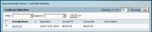
In the resulting page, shown in Figure 8-15, specify the CA certificate location and specify whether you want to use it for EAP-TLS authentication to trust/not trust clients and click Submit. This results in the page shown in Figure 8-16.
Figure 8-15. CA Certificate Install on ACS 5.1
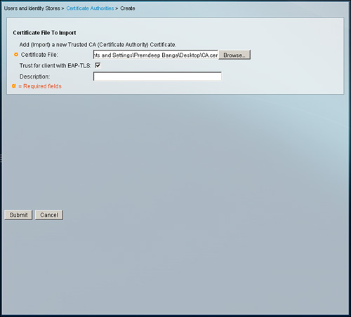
Figure 8-16. CA Certificate Installed on ACS 5.1
Step 6. Finally, install the server certificate on ACS 5.1 by going to System Administration > Configuration > Local Server Certificates > Local Certificates > Add.
This time, as illustrated in Figure 8-17, you need to select the Bind CA Signed Certificate option and press Next. This enables the ACS server to bind the CSR generated previously with the server certificate obtained from the CA.
Figure 8-17. Bind CA Signed Certificate Option
On the next page, shown in Figure 8-18, you need to specify the ACS server certificate location. In addition, you also need to specify the purpose of the certificate, that is, for EAP protocol or for Management Interface purposes. After the information has been provided, click Finish to load the server certificate on ACS. Figure 8-19 shows the final screen.
Figure 8-18. Server Certificate Installation on ACS 5.1
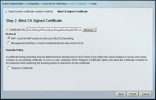
Figure 8-19. Server Certificate(SJACSCert) Installed on ACS 5.1

Configuring EAP-MD5 on ACS
This section provides configuration details for EAP-MD5 on ACS 4.2 and ACS 5.1.
EAP-MD5 Configuration on ACS 4.2
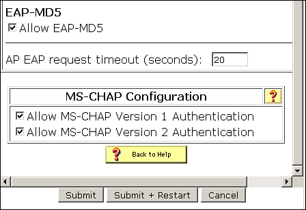
To configure/enable EAP-MD5 on ACS 4.2, go to System Configuration > Global Authentication Setup and under EAP-MD5, check Allow EAP-MD5 and click Submit + Restart as shown in Figure 8-20.
Figure 8-20. EAP-MD5 on ACS 4.2
EAP-MD5 Configuration on ACS 5.1
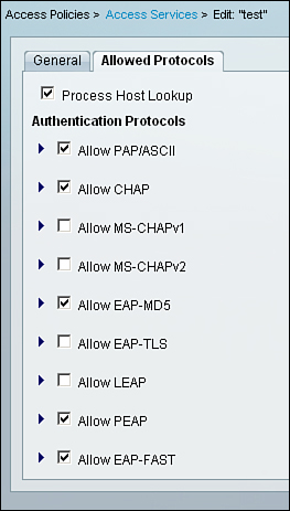
In ACS 5.1, for EAP-MD5 to be allowed under the access policy, go to Access Policies > Access Services.
You can create a new access service or edit an already configured access service.
Go to the Allowed Protocols section in the access policy, as shown in Figure 8-21, and check Allow EAP-MD5 in the access policy to allow it and click Submit.
Figure 8-21. EAP-MD5 on ACS 5.1
Configuring PEAP on ACS
Before configuring ACS for PEAP authentication, ensure that you have an ACS server certificate already installed on ACS 4.2 and ACS 5.1. The ACS server certificate can be self-signed or obtained from an external CA.
PEAP Configuration on ACS 4.2
On ACS 4.2, go to System Configuration > Global Authentication Setup.
Under PEAP, check the PEAP version that you want to allow:
• Allow EAP-MSCHAPv2
• Allow EAP-GTC
• Allow Posture Validation
• Allow EAP-TLS
After selecting the PEAP version, click on Submit + Restart.
Figure 8-22 shows an example where EAP-MSCHAPv2 has been enabled.
Figure 8-22. PEAP/EAP-MSCHAPv2 on ACS 4.2
PEAP Configuration on ACS 5.1
In ACS 5.1, PEAP needs to be allowed under the access policy. Go to Access Policies > Access Services.
You can create a new access service or edit an already configured access service.
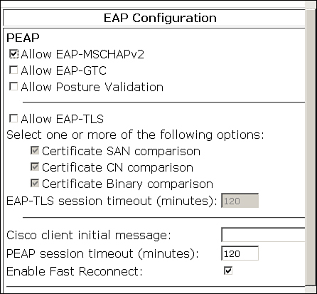
Go to the Allowed Protocols section in the access policy, as shown in Figure 8-23, and check Allow PEAP in the access policy to allow it. Expand the Allow PEAP option to select any of the PEAP versions that you want to allow.
Figure 8-23. PEAP/EAP-MSCHAPv2 on ACS 5.1
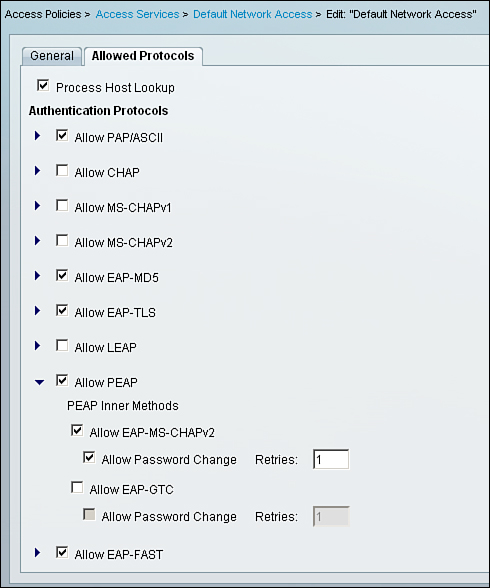
Figure 8-23 shows an example where EAP-MSCHAPv2 has been enabled.
You can configure other related PEAP settings from: System Administration > Configuration > Global System Options > PEAP Settings.
Configuring EAP-TLS on ACS
Before configuring ACS for EAP-TLS authentication, ensure that you have an ACS server certificate already installed on ACS 4.2 and ACS 5.1. The ACS server certificate can not be self signed, it must be obtained from an external CA.
EAP-TLS Configuration on ACS 4.2
On ACS 4.2, go to System Configuration > Global Authentication Setup. Under EAP-TLS check Allow EAP-TLS, as shown in Figure 8-24, and click Submit + Restart to commit the changes made on ACS configuration.
Figure 8-24. EAP-TLS on ACS 4.2

EAP-TLS Configuration on ACS 5.1
In ACS 5.1, EAP-TLS needs to be allowed under the access policy. Go to Access Policies > Access Services. You can create a new access service or edit an already configured access service.
Go to the Allowed Protocols section in the access policy, and check Allow EAP-TLS in the access policy to allow it, as shown in Figure 8-25, and then click Submit.
Figure 8-25. EAP-TLS on ACS 5.1

You can configure other related EAP-TLS settings from System Administration > Configuration > Global System Options > EAP-TLS settings.
For EAP-TLS authentication on ACS 5.1, you must also configure the certificate authentication profile according to your requirements. By default, there exists a predefined certificate authentication profile called CN Username. Certificate authentication profiles define how X509 certificate information is to be used for a certificate-based request. In these profiles, you can select from a list of available attributes to be used as the username. The selected attribute is used to populate the username field and is used to query the LDAP or AD identity store. You can configure the certificate authentication profile on ACS 5.1 from Users and Identity Stores > Certificate Authentication Profile.
Dynamic VLAN Assignment: ACS Configuration
As discussed in the “VLAN Assignment” section earlier in the chapter, following vendor-specific tunnel attributes need to be configured in the RADIUS server for dynamic VLAN assignment:
• [64] Tunnel-Type = VLAN
• [65] Tunnel-Medium-Type = 802
• [81] Tunnel-Private-Group-ID = VLAN name or VLAN ID
Dynamic VLAN Assignment for ACS 4.2
On ACS 4.2, first ensure that attributes 64, 65, and 81 are enabled to be configured on ACS. This can be done from Interface Configuration > RADIUS (IETF).
For User/Group, check the following attributes and click Submit to configure the attributes on the User/Group level:
• [064] Tunnel-Type
• [065] Tunnel-Medium-Type
• [081] Tunnel-Private-Group-ID
As an example, Figure 8-26 shows the configuration to dynamically assign VLAN 10 to a user.
Figure 8-26. Dynamic VLAN Assignment for ACS 4.2

Dynamic VLAN Assignment for ACS 5.1
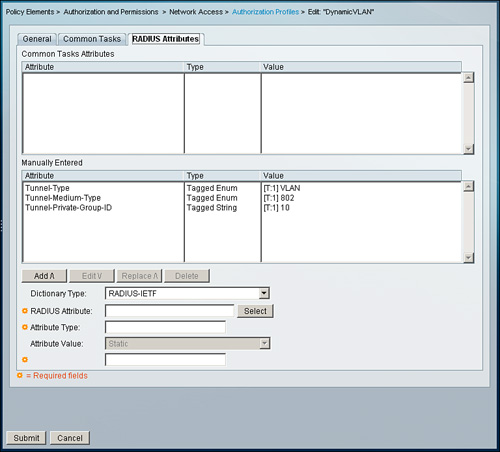
For ACS 5.1, you first need to create an authorization profile that will have the RADIUS IETF attributes for VLAN assignment. Go to Policy Elements > Authorization and Permissions > Network Access > Authorization Profiles.
Create or edit an authorization profile and go to the RADIUS Attributes tab. In this section, configure the attributes for dynamic VLAN assignment. As an example, create an authorization profile to assign a user in VLAN 10 with the following attribute configuration:
• Dictionary Type: RADIUS-IETF
• RADIUS Attribute: Tunnel-Type
• Attribute Type: Tagged Enum
• Attribute Value: Static: VLAN
• Tag: 1
• Dictionary Type: RADIUS-IETF
• RADIUS Attribute: Tunnel-Medium-Type
• Attribute Type: Tagged Enum
• Attribute Value: Static: 802
• Tag: 1
• Dictionary Type: RADIUS-IETF
• RADIUS Attribute: Tunnel-Private-Group-ID
• Attribute Type: Tagged String
• Attribute Value: Static: 10
• Tag: 1
Figure 8-27 illustrates the preceding configuration.
Figure 8-27. Dynamic VLAN Assignment for ACS 5.1
After the authorization profile is created, you can apply the profile using the access policy’s authorization section.
There is another way to accomplish this and an easier one. To configure this, go to Policy Elements > Authorization and Permissions > Network Access > Authorization Profiles > Create/Edit > Common Tasks > VLAN > VLAN ID/Name.
Here you can specify VLAN statically by choosing the Static option and specifying the VLAN ID/name in the Value box provided. You can also choose the Dynamic option and specify an external identity store from which the value can be retrieved. If you choose Dynamic, you need to specify the external identity store dictionary from which the value will be populated. The external identity store dictionary is configured under External Identity Stores.
Lab Scenario #7: Configuring Switch, ACS, and Windows XP for IEEE 802.1X Authentication Using EAP-MD5
ABC Inc. has a requirement to secure all the Windows XP workstations connected to the Layer 2 switch port. The company has three departments: HR, Finance, and Development. All three departments have access to the conference hall. A requirement dictates that whenever any members of the HR team moves to the conference hall, they should be authenticated using ACS and then placed into VLAN 5; similarly, members of the Finance team should be assigned to VLAN 6, and members of the Development team should be assigned to VLAN 7 should they move to the conference hall. You need to configure the switch, client, and ACS for EAP-MD5 authentication.
Lab Setup
This lab setup requires one switch, one ACS server, and one Windows XP client that can be used by any department individual to log in. Figure 8-28 shows the setup required.
Figure 8-28. Setup for Lab 7

Lab Solution
The solution to this scenario assumes certain things that are very basic and are expected to be configured by the candidate using the knowledge obtained from previous sections.
The assumptions are as follows:
A. Switch entry exists in ACS configuration.
• For ACS 5.1: Under Network Resources > Network Devices and AAA Clients
• For ACS 4.2: Under Network Configuration > ... > AAA Clients
B. Three groups have been created in the ACS configuration: HR, Finance, and Development.
• For ACS 5.1: Under Users and Identity Stores > Identity Groups
• For ACS 4.2: Under Group Setup
C. Users exist under each group configured in section B:
• ACS 5.1: Under Users and Identity Stores > Internal Identity Stores > Users
• ACS 4.2: User Setup
ACS 4.2 Configuration Requirement
A. Ensure that RADIUS attributes for dynamic VLAN assignment are enabled for the group. Go to Interface Configuration > RADIUS (IETF) and check that the following attributes are configured as illustrated in Figure 8-29:
• [064] Tunnel-Type
• [065] Tunnel-Medium-Type
• [081] Tunnel-Private-Group-ID
Figure 8-29. Attributes for Dynamic VLAN Assignment
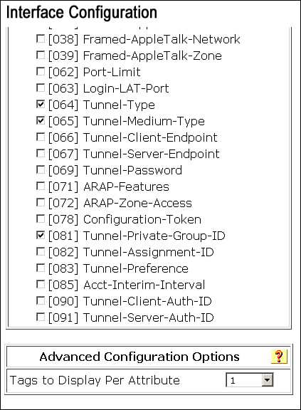
If you are not sending multiple attributes for other RADIUS IETF attributes, change Tags to Display Per Attribute to 1.
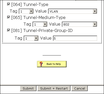
B. Under each individual group, configure the attributes as shown in Figure 8-30:
HR group:
• [064] Tunnel-Type, Tag: 1, Value: VLAN
• [065] Tunnel-Medium-Type, Tag: 1, Value: 802
• [081] Tunnel-Private-Group-ID, Value: 5
• [064] Tunnel-Type, Tag: 1, Value: VLAN
• [065] Tunnel-Medium-Type, Tag: 1, Value: 802
• [081] Tunnel-Private-Group-ID, Value: 6
Development group:
• [064] Tunnel-Type, Tag: 1, Value: VLAN
• [065] Tunnel-Medium-Type, Tag: 1, Value: 802
• [081] Tunnel-Private-Group-ID, Value: 7
Figure 8-30. Attributes Configured for the HR Group on ACS 4.2
C. Although by default EAP-MD5 is enabled on ACS, you can verify that it is enabled from System Configuration > Global Authentication Setup.
After configuring for attributes for individual group and ensuring the EAP-MD5 is enabled, click Submit + Restart to ensure that settings take effect.
ACS 5.1 Configuration Requirement
A. Create a device filter named Dot1xSwitch for the switch configured under the Network Resources > Network Devices and AAA Clients section.
The device filter can be created from Policy Elements > Session Conditions > Network Conditions > Device Filters as shown in Figure 8-31.
Figure 8-31. Device filter on ACS 5.1

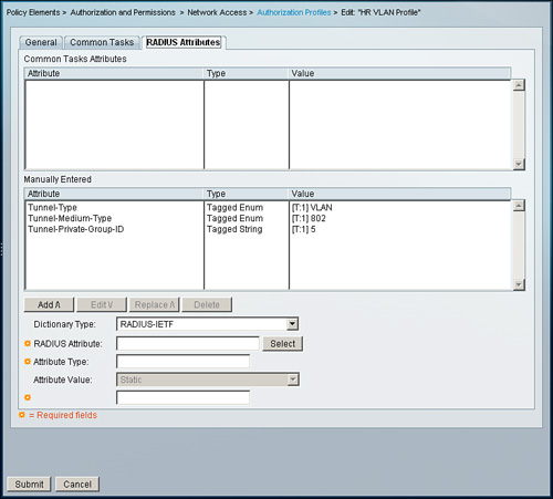
B. Create three authorization profiles under Policy Elements > Authorization and Permissions > Network Access > Authorization Profiles:
• HR VLAN Profile
• Finance VLAN Profile
• Development VLAN Profile
Under the RADIUS Attributes tab, configure following two attributes for each profile:
• Dictionary Type: RADIUS-IETF
• RADIUS Attribute: Tunnel-Type
• Attribute Type: Tagged Enum
• Attribute Value: Static: VLAN
• Tag: 1
• Dictionary Type: RADIUS-IETF
• RADIUS Attribute: Tunnel-Medium-Type
• Attribute Type: Tagged Enum
• Attribute Value: Static: 802
• Tag: 1
For the last attribute required for dynamic VLAN assignment, you must use the values 5, 6, and 7 for the Attribute Value for each respective profile:
• Dictionary Type: RADIUS-IETF
• RADIUS Attribute: Tunnel-Private-Group-ID
• Attribute Type: Tagged String
• Attribute Value: Static: 5
• Tag: 1
• Dictionary Type: RADIUS-IETF
• RADIUS Attribute: Tunnel-Private-Group-ID
• Attribute Type: Tagged String
• Attribute Value: Static: 6
• Tag: 1
• Dictionary Type: RADIUS-IETF
• RADIUS Attribute: Tunnel-Private-Group-ID
• Attribute Type: Tagged String
• Attribute Value: Static: 7
• Tag: 1
As an example, Figure 8-32 shows what the HR VLAN profile will look like.
Figure 8-32. Authorization Profile HR VLAN Profile on ACS 5.1
Note
VLAN assignment on ACS 5.1 can also be configured using a common task as described in the section “Dynamic VLAN Assignment for ACS 5.1.”
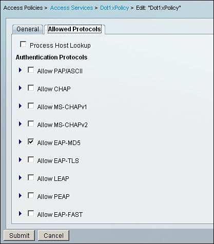
C. Create an access service named Dot1xPolicy under Access Policies > Access Services as shown in Figure 8-33. For Policy Structure for access services, check only Identity and Authorization. Under Allowed Protocols, use only Allow EAP-MD5 as shown in Figure 8-34.
Figure 8-33. Access Service Dot1xPolicy for Dynamic VLAN Assignment
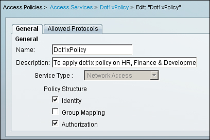
Figure 8-34. EAP-MD5 as the Only Allowed Protocol Under Access Service
D. Create a rule to match and to apply the access service configured in the previous step from Access Policies > Access Services > Service Selection Rules as shown in Figure 8-35. Under Conditions, select
• Protocol: match: Radius
• Device Filter: match: Dot1xSwitch
Figure 8-35. Rules to Apply Dot1xPolicy
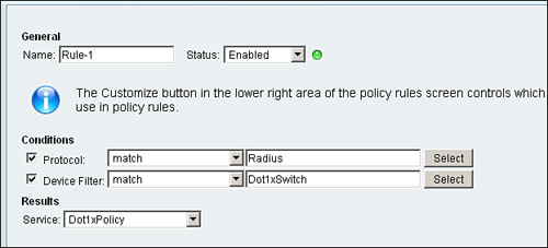
For Results, select Dot1xPolicy as the service.
Note
Choose the Customize button to create the required conditions.
Switch Configuration Requirements
Step 1. Enable the AAA model on the switch:
Switch(config)# aaa new-model
Step 2. Configure the RADIUS server configuration on the switch:
Switch(config)# radius-server host 192.168.26.7 key cisco
Step 3. Enable IEEE 802.1X globally on the switch:
Switch(config)# dot1x system-auth-control
Step 4. Configure the switch for IEEE 802.1X authentication:
Switch(config)# aaa authentication dot1x default group radius
Step 5. Configure the switch for IEEE 802.1X authorization, which is mandatory for dynamic VLAN assignment. This command tells the switch to process attributes returned by the RADIUS server:
Switch(config)# aaa authorization network default group radius
Step 6. Configure the interface for single host mode IEEE 802.1X authentication:
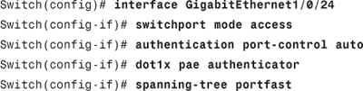
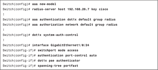
Example 8-1 shows the full switch configuration.
Example 8-1. IEEE 802.1X Configuration on Switch
Client Configuration Requirements
You need to configure the Windows XP client for MD5 authentication, which can be done from Control Panel > Network Connections > Select the LAN connection > Right-click > Properties > Authentication.
From the screen in Figure 8-36, ensure that Enable IEEE IEEE 802.1X authentication is checked.
Figure 8-36. MD5 Configuration on Client
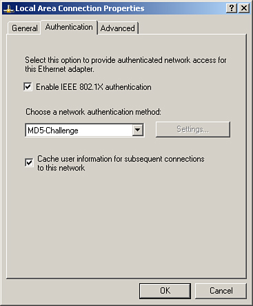
Select MD5-Challenge under Choose a network authentication method.
Tip
If the Authentication tab is not available, start the Wireless Zero Configuration service on Windows XP Service Pack 2 and Wired AutoConfig on Windows XP Service Pack 3.
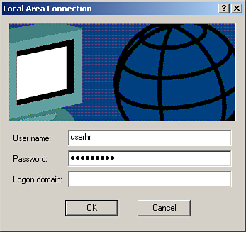
When the client is plugged in the switch port configured for IEEE 802.1X authentication, the client PC will get a balloon on the LAN network connection in the system tray. Click on the balloon and it will pop up with a login window as shown in Figure 8-37.
Figure 8-37. Login Windows for MD5 Authentication
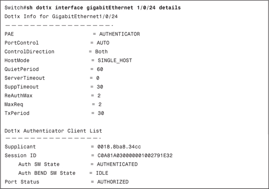
Example 8-2 displays the show dot1x interface gigabitEthernet 1/0/24 details output after successful authentication. This output can be a starting point while troubleshooting issues related to IEEE 802.1X. This provides you with information about the configuration on the switchport and the current state of the switchport.
The Dot1x Info for Interface section covers the configuration part of the interface and provides information about the following:
• PAE
• Port Control
• Control Direction
• Host Mode
• Quiet Period
• Server Timeout
• Supplicant Timeout
• ReAuth Max
• Max Request
• Tx Period
The current state of the switchport is under the Dot1x Authenticator Client List section. This section provides you with following information.
• Supplicant: MAC address of the supplicant
• Session ID: Session ID used for authentication, authorization and accounting
• Auth SM State: Shows current authentication state
• Port Status: Current port status
Based on the information available from this output, further action plans can be drawn to troubleshoot the issue.
Example 8-2. show dot1x interface gigabitEthernet 1/0/24 details Command Output
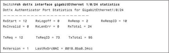
Example 8-3 displays the show dot1x interface gigabitEthernet 1/0/24 statistics output after successful authentication. This command is useful in understanding the type of EAP information received or sent on/from the switchport:
• RxStart: Number of valid EAPOL-start frames received
• RxLogoff: Number of EAPOL-logoff frames received
• RxResp: Number of valid EAP-response frames (other than response/identity) received
• RxRespID: Number of EAP-response/identity frames received
• RxInvalid: Number of EAPOL frames with unrecognized frame type received
• RxLenError: Number of EAPOL frames with invalid body length field received
• RxTotal: Number of valid EAPOL frames (any type) received
• TxReq: Number of EAP-request frames (other than request/identity) sent
• TxReqID: Number of EAP-request/identity frames sent
• TxTotal: Number of EAPOL frames (any type) sent.
• RxVersion: Number of packets received in IEEE IEEE 802.1X version 1 format
• LastRxSrcMAC: Source MAC address carried in the most recently received EAPOL frame
Example 8-3. show dot1x interface gigabitEthernet 1/0/24 statistics Command Output
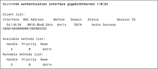
Example 8-4 displays the show authentication interface gigabitEthernet 1/0/24 output after successful authentication. This output shows authentication manager events on the switch. This is useful in determining the method (dot1x, mab or webauth) by which a supplicant is authenticated; the current domain (Data or Voice) under which the supplicant is placed; and the current status for the switchport.
The following are the status values that can be found in the show authentication output:
• Idle: It means session has been initialized and no methods have been run yet.
• Running: It means a method is running for this session.
• No methods: It means no method has provided a result for this session.
• Authc Success: It means a method has resulted in authentication successful for this session.
• Authc Failed: It means a method has resulted in authentication fail for this session.
• Authz Success: It means all features have been successfully applied for this session.
• Authz Failed: It means a feature has failed to be applied for this session.
Example 8-4. show authentication interface gigabitEthernet 1/0/24 Command Output
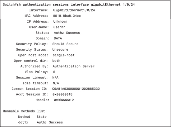
Example 8-5 displays the show authentication sessions gigabitEthernet 1/0/24 output after successful authentication. This is another useful command to check the state of a switchport (that is, domain, host mode, username, status, VLAN policy, and so on). In this show output, you will also have State, which can have following values:
• Not run: The method has not run for this session.
• Running: The method is running for this session.
• Failed over: The method has failed and the next method is expected to provide a result.
• Authc Success: The method has provided a successful authentication for the session.
• Authc Failed: The method has provided a failed authentication for the session.
Example 8-5. show authentication sessions interface gigabitEthernet 1/0/24
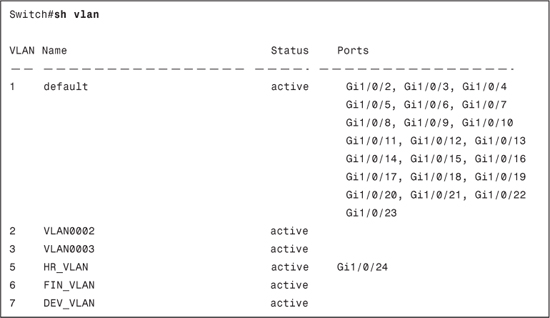
Example 8-6 displays the show vlan output before authentication. This command can be used before the authentication process to check current VLAN for the switchport.
Example 8-6. show vlan Output Before Authentication

Example 8-7 displays the show vlan output after authentication. This command can be used to verify the dynamic VLAN assignment feature to ensure that the switchport has successfully transitioned to required VLAN.
Example 8-7. show vlan Output After Authentication
Example 8-8 displays an excerpt of the debug radius authentication output. This debug can be used to troubleshoot authentication failures. In this debug, you can verify the information passed between the authentication server and the switch. As shown in the debugs in Example 8-8, you can clearly see information such as User-Name, Tunnel-Type, Tunnel-Medium-Type, and Tunnel-Private-Group being passed over to the RADIUS server.
Example 8-8. debug radius authentication Output Excerpt

To view the log for successful authentications and failures on ACS 4.2, you need to go to Reports and Activity > Passed Authentications and Reports and Activity > Failed Attempts.
For ACS 5.1, you first need to go to Monitoring and Reports > Launch Monitoring & Report Viewer.
This will launch a new browser window with Cisco Secure ACS View. In Cisco Secure ACS View, you need to go to the following:
• Monitoring & Reports > Reports > catalog > AAA Protocol > RADIUS Authentication
• Monitoring & Reports > Reports > catalog > AAA Protocol > AAA Diagnostics
Lab Scenario #8: Configuring Switch, ACS, and Windows XP for IEEE 802.1X Authentication Using PEAP
The lab setup will remain the same as Lab Scenario #7; the only requirement that will change is to change the authentication method from EAP-MD5 to PEAP.
Lab Solution
The ACS 4.2 configuration requirement is to install the CA (the CA that issued the ACS server identity certificate) and server certificate (the identity certificate for ACS) and enable PEAP on ACS 4.2 as described earlier in the section “Configuring PEAP on ACS.”
The ACS 5.1 configuration requirement is to install the CA (CA that issued ACS server identity certificate) and server certificate (the identity certificate for ACS) and check only the Allow PEAP and PEAP Inner Methods as Allow EAP-MS-CHAPv2 in the Dot1xPolicy on ACS 5.1 as described previously in the section “Configuring PEAP on ACS.”
For the switch configuration requirement, the configuration will remain the same as configured in Lab Scenario #7.
The client configuration requirements for this lab are satisfied as follows:
A. Ensure that the CA certificate that was installed on the ACS server is also installed on the client machine because, in PEAP, the client validates the RADIUS (ACS) server certificate during authentication.
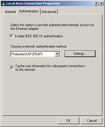
B. Configure the Windows XP client for PEAP authentication from Control Panel > Network Connections > Select the LAN connection > Right click > Properties > Authentication. Ensure that Enable IEEE IEEE 802.1X authentication is checked and select Protected EAP (PEAP) under Choose a network authentication method as shown in Figure 8-38.
Figure 8-38. PEAP Configuration on Client Machine
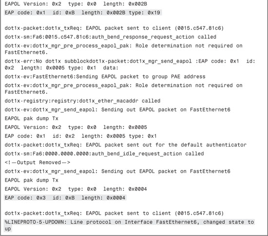
Example 8-9 displays an excerpt of the debug dot1x all output. Before authorizing a port, there are multiple exchanges that take place between the supplicant and the RADIUS server. The debug shown has some portions removed to make it more understandable. In these debugs, you can clearly see the following:
EAP-Request/Identity (EAP code: 0x1 and type: 0x1)
You can also see that EAP authentication attempted is PEAP as the type shown in the debug is 0x19 (equivalent to decimal 25, PEAP).
At the end you can see authentication passing and an EAP success (EAP code: 0x3).
Example 8-9. debug dot1x all Output Excerpt

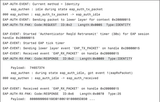
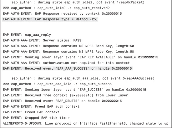
Example 8-10 displays an excerpt of the debug eap all output. In this debug output, you can see all the exchanges; that is, EAP-Request/identity, EAP-Response/identity, and EAP-Success.
Example 8-10. debug eap all Output Excerpt
Lab Scenario #9: Configuring Switch, ACS, and Windows XP for IEEE 802.1X Authentication Using EAP-TLS
The lab setup will remain the same as Lab Scenario #7; the only requirement that will change is the authentication method from EAP-MD5 to EAP-TLS.
Lab Solution
ACS 4.2 configuration requirement:
The ACS 4.2 configuration requirement is to install CA (the CA that issued the ACS server identity certificate and the CA that issued certificates to supplicants) and server certificate (the identity certificate for ACS) and enable EAP-TLS on ACS 4.2 as described in the section “Configuring EAP-TLS on ACS.”
The ACS 5.1 configuration requirement is to install the CA and ACS server certificate on ACS 5.1 and check only Allow EAP-TLS in Dot1xPolicy on ACS 5.1 as described in the section “Configuring EAP-TLS on ACS.”
For the switch configuration requirement, the configuration will remain the same as configured in Lab Scenario #7.
The client configuration requirements for this lab are satisfied as follows:
A. Ensure that the CA certificate and a client certificate issued to the client are installed on the client machine.
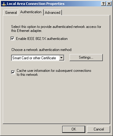
B. Configure the Windows XP client for EAP-TLS authentication from Control Panel > Network Connections > Select the LAN connection > Right click > Properties > Authentication. Ensure that Enable IEEE IEEE 802.1X authentication is checked and Select Smart Card or other Certificate under Choose a network authentication method as shown in Figure 8-39. Further, click on Settings and select Use a certificate on this computer option. Also choose the Validate server certificate option and click Trusted root certificate authority and select the root certification authority server for the enterprise EAP-TLS clients and ACS server.
Figure 8-39. EAP-TLS Configuration on Client
Useful show Commands
show commands can provide very useful and meaningful output and can assist in troubleshooting various issues. show commands are generally used for confirming the change made in a device configuration or the current state/status of/on the device.
Useful show commands in Cisco IOS switches include the following:
show dot1x [all | interface type slot/port]: Displays IEEE IEEE 802.1X statistics, administrative status, and operational status for the switch or for the specified port.
• show authentication registrations: Displays details of all methods registered with the Auth Manager.
show authentication interface interface: Displays all the Auth Manager details associated with the specified interface.
show authentication method method: Displays all clients authorized by a specified authentication method. Valid values are dot1x, mab and webauth.
show authentication sessions [handle handle] [interface interface] [mac mac] [method method] [session-id session-id]: Displays details of the current Auth Manager sessions (for example, client devices).
show mab {all | interface type slot/port} [detail]: Displays MAC authentication bypass (MAB) information.
Troubleshooting IEEE 802.1X
The following commands can be useful while troubleshooting IEEE 802.1X issues:
• debug aaa authentication: Displays debug messages for authentication only.
• debug aaa authorization: Displays debug messages for authorization only.
• debug aaa accounting: Displays debug messages for accounting only.
debug dot1x [all | errors | events | feature | packets | redundancy | registry | state-machine]: Enables debugging of the IEEE 802.1X feature.
debug eap [all | method] [authenticator | peer] {all | errors | events | packets | sm}: Enables debugging of the Extensible Authentication Protocol (EAP) activity.
debug radius [accounting | authentication | brief | elog | failover | retransmit | verbose]: Displays RADIUS debugging messages for all users and sessions, including decoded RADIUS messages.
Tip
Make sure that you turn off debug after required logs are collected. This can be done by using no for of the debug command or all the debugs can be turned off in one go by using the command undebug all.
Note
It is recommended that debugs/traces on the device must be enabled with caution as they can affect CPU utilization and device performance. It is best to use debug commands during periods of lower network traffic and fewer users. Debugging during these periods decreases the likelihood that increased debug command processing overhead will affect system use.
Summary
This chapter familiarized you with IEEE 802.1X concepts as well as explored IEEE 802.1X configuration from a Cisco switch perspective. In addition, the key takeaways and concepts covered in this chapter are as follows:
• IEEE 802.1X standard has three main entities: client or supplicant, authenticator, and authentication server.
• EAP is the key protocol in IEEE 802.1X used to pass the authentication information between the supplicant and authentication server.
• In EAP, four type of messages can be sent: Request, Response, Success, and Failure.
• EAP requests and responses are subdivided using the EAP Type filed.
• EAPOL is used to encapsulate the EAP messages.
• EAPOL has five messages: EAPOL-Packet, EAPOL-Start, EAPOL-Logoff, EAPOL-Key, and EAPOL-Encapsulated-ASF-Alert.
• A few of the more common EAP types are EAP-MD5, LEAP, PEAP, EAP-TLS, and EAP-FAST.
• IEEE 802.1X basic configuration on switch.
• IEEE 802.1X host modes: single, multiple, multidomain, multiauthentication, and pre-authentication open access.
• Guest and restricted VLAN feature with IEEE 802.1X.
• MAC authentication bypass feature for non IEEE 802.1X-compliant supplicants.
• Dynamic VLAN assignment for IEEE 802.1X-authenticated clients.
• Some of the more commonly used IEEE 802.1X timers are quiet period, tx-period, supp-timeout, server-timeout, and max-req.
• IEEE 802.1X accounting includes START, INTERIM, and STOP accounting packet types.
• How to configure EAP-MD5, PEAP, and EAP-TLS on ACS 4.2 and ACS 5.1.