
Chapter 9. Entity Services with Java

9.1 Inside the Java Entity Service
9.2 Java Entity Service Design and Implementation
Existing data architectures can be problematic for businesses, as they pose a number of inherent challenges. For example:
• Multiple Versions of the Truth – Data concerning the same business entity contains different values in different systems. For example, an enterprise can store customer information on several databases, which have little to no inter-database integration or synchronization.
• Inconsistent Information – Applications that can return varying results when asked for the same information apply different business rules to the data, because of application-specific methods to retrieve and process data or the applicable data formats supported.
• Difficulty in Managing Geographically Distributed Supply Chains – Information cannot be properly propagated along a supply chain consisting of internal and external partners in different geographical locations, which creates the need for manual intervention.
Addressing these issues to establish a consistent method of accessing and processing business data is a fundamental objective of the entity service model. Entity services represent data that is not limited to one business domain, and are instead supported by canonical data models across the entire service inventory. Being highly reusable, entity services are generally utilized by higher-level task services.
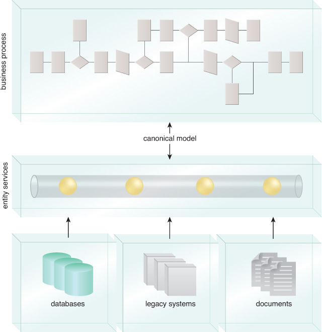
Unlike utility services, entity services are business-centric and have correspondingly business-based functional contexts. Entity services are also data-centric, and traditional create-read-update-delete (CRUD) interfaces are substituted for useful capabilities that fall within the services’ functional boundaries. Therefore, entity services provide a level of indirection between higher-level process services and the underlying data sources, as shown in Figure 9.1.
9.1 Inside the Java Entity Service
Entity service architecture is substantially independent of the programming platform used for its implementation. Let’s explore the design and implementation considerations associated with building entity services in Java.
Architectural Considerations
A typical enterprise has formal data models to describe core data elements and their formats exactly, with some elements of the model limited to a certain domain. Entities like Customer, Order, or Product occur in applications across a number of domains. Many companies use multiple disparate systems to store their own versions of data in their own formats. The data must be transformed manually for every interaction between these systems and any other internal or external system.
For example, many companies have several customer databases that store details relevant to the particular application that uses the data. The enterprise data model attempts to consolidate these different formats by defining a structure that satisfies all potential requests for the data and serves as a canonical model across multiple domains and applications to provide a consistent view, as seen in Figure 9.2.
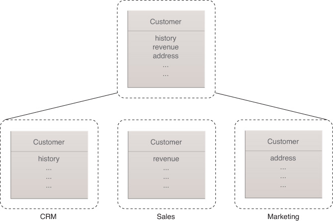
Figure 9.2 The canonical form of the enterprise data model consolidates different domain-specific views on data.
Entity services are the vehicle for providing access to data that conforms to the canonical model, which is reflected in the messages travelling in and out of the services. The entity service implementation manages differences between how data is stored in the data source and the canonical model. The way in which data can be retrieved from data stores is also encapsulated in the implementation, which is transparent to the service consumer.
Some data can be retrieved by directly accessing a relational database, instead of a JDBC-based API or employing resource utility services. Other data must be accessed via a particular application interface, such as a mainframe transaction. Entity services are responsible for transforming data into a canonical form supported by the enterprise data model, which is typically described in XML Schema.
Domain Entities vs. Message Entities
An entity service can act as an access point to a potentially large set of data sources. This level of indirection supports both a canonical data view and specialized interfaces that serve the requirements of certain service consumers. To help distinguish these views, we’ll refer to canonical data models within a service inventory as a domain entities and the data models specific to an entity service contract as message entities.
Specialized interfaces are created because data models instantiated into Java objects in memory can consist of large graphs of objects, which are expensive to serialize into messages for transfer over a network and/or between process boundaries. Figure 9.3 illustrates the relationship between domain and message entities.
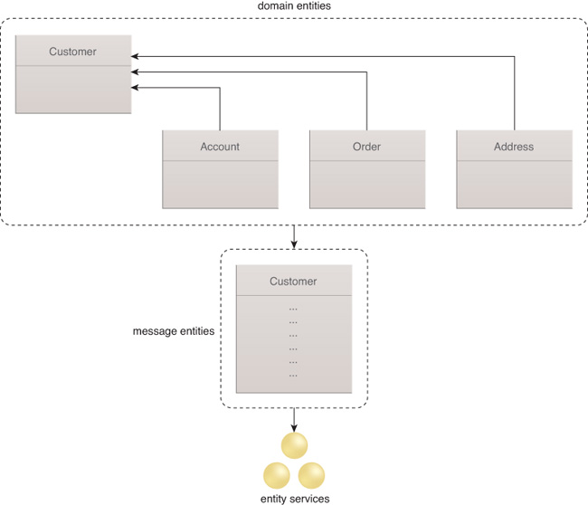
Consider, for example, an order entity. Each order typically references the customer that initiated the order and includes individual line items that refer to products. The combined relevant information about an order creates a potentially large amount of data for retrieval from persistent storage. Java or JPA entities implicitly support lazy instantiation mechanisms that only load the required data.
Typical JPA implementations allow for the interception of client requests and additional data to be loaded from its source when needed. However, this approach cannot be applied for services, because a service must always return a complete message that supports call-by-copy semantics. Exposing the full data model is often inefficient in a service context.
If services are identified and specified with a view of the business and its processes, they will include a definition of the messages that flow into and out of each service operation to facilitate the creation of message entity definitions. At the same time, domain entities are created via the definition of a canonical data model. Subsequently, the entity service in its implementation maps existing data from a variety of sources into canonical domain objects (unless already supported by the existing environment) and transforms data into a variety of message objects exposed via the service interface.
Domain entities often follow a different lifecycle than message entities. The definition of domain objects does not change as frequently as the definition of message entities, which are subject to new or constantly changing service consumer requirements. Different design approaches exist to address a dynamic definition in relation to Java, examples of which are explored in the following sections.
Data Aggregation
Frequently, the data exposed through an entity service must be aggregated from a variety of sources. One-to-one relationships between the domain and message entities the service uses and the data sources that exist in the enterprise are often absent.
For example, a customer domain entity may consist of attributes for retrieval from multiple databases, such as from a relational database table, third-party Web service, or mainframe transaction invoked using an adapter. The entity service shields its service consumers from these details. The way in which the data is collected and aggregated can be changed at any time without affecting clients.
Data aggregation can be problematic if data is kept at more than one location, which differs between systems. Some business data can be replicated across several data sources at specific points in time, such as an overnight batch load. The data may not be the same for some time. An explicit decision must be made about which version of data represents the master copy, so that the entity service can use the appropriate data source.
Data ownership is directly related to data aggregation. Whenever data is changed via an entity service, it must be ensured that the service can update the data without conflicting with other existing applications. Some applications are built to assume exclusive access to the underlying database. Being tightly coupled to the database creates unwanted side effects when changing data without going through the owning application.
In situations where data is owned by an existing application, the entity service implementation should go through the owning application to make updates to the data. Additional considerations can arise when combining multiple entity services to provide an aggregated view of data, which are explored in Chapter 11.
Data Access Modes
Entity services do not need to support a plain CRUD interface. Many business processes will never need to update a given domain object or require any service operation that supports writing data.
The need to create and update data immediately raises questions about the transactional characteristics of a service. Should the appropriate table and/or row be locked from access by other service consumers in case a service consumer retrieves data stored in a relational database with the intention of performing updates later? If an update to the data is made, should the system check whether the data has been updated since being read by the service consumer? In a traditionally built application, these issues would be addressed by leveraging support for transactions. A piece of logic that needs exclusive write access to a piece of data would set the boundary of an atomic transaction to prevent concurrent updates. The appropriate database locks are usually put in place.
The Java EE standard and EJBs support a variety of access modes for data without requiring Java coding. Instead, declarative attributes can be set on EJB classes that let the system determine which transactional behavior is desired. Moreover, most Java EE-compliant application servers offer support for declaring data access or locking modes for a persistent entity EJB. For example, a mechanism to read a persistent entity with a pessimistic write lock indicates that other clients cannot update the same data until the owning transaction has completed.
However, these implementation details are not exposed on the entity service interface. Therefore, transactional characteristics and data access modes will not appear on a service interface. A series of invocations on a given service should not be related to each other. Allowing a service consumer to invoke tasks, such as “start a transaction” or “put a lock on this row of data,” violates the Service Statelessness design principle.
A common method of accessing and changing data in a service-oriented architecture is called the disconnected or optimistic approach. A service consumer using this approach will obtain a copy of the data by invoking a service, which does not place any locks on the underlying physical resources. Other service consumers interested in the same data are automatically allowed full access. After the service consumer has finished updating, the data is sent back to the service for permanent storage.
The optimistic approach assumes that, in a large majority of cases, no other service consumer will have made an update to the same data while the first service consumer was in the middle of a transaction. In cases where a conflict is detected, the behavior depends on the specific requirements of the application. In some cases, overwriting the updated data is acceptable, while in other cases an error is reported back to the service consumer. A high-level overview of the steps involved in disconnected data access is shown in Figure 9.4.

Figure 9.4 Disconnected data access leaves no locks on the data source while the data is being worked on by the service consumer.
SDO is based on a disconnected data access approach. The disconnected mode does not support the defining of transactional boundaries. Applications can require the ability to define transactional boundaries for a series of services invocations, such as being able to specify that either all invocations or none are made permanent within a given boundary. For such instances, the WS-AtomicTransaction standard defines how to turn a service into a transactional resource that is then coordinated as part of a two-phase commit-style scenario.
Change Notifications
During the time in which a service consumer is working with data, that data is not physically locked or otherwise prevented from being updated by other service consumers. Data can become stale and other users may not receive the actual state. Preventing stale data from being altered requires clients to be notified of changes made to the data offered by an entity service. However, some Web-based services are incapable of actively sending out notifications about certain events that have occurred.
9.2 Java Entity Service Design and Implementation
Entity services are highly reusable, based on their lack of affinity to a particular business domain. At the same time, design challenges are raised because the services must satisfy service consumers with different specific needs.
An entity service can be performance-critical with a focus on short response times, while other times the service can be run in batch mode with a high throughput of messages.
Service consumers can retrieve large amounts of data with a single invocation, which requires the service implementation to aggregate data from several sources for more fine-grained access with small message sizes. The varying functional and non-functional requirements will affect the design and implementation of an entity service in Java in different ways that are explored in the following sections.
Entity Service Design
The entity service acts as a level of indirection and isolation between service consumers of data and their source. An existing physical data model is translated into a view relevant to business service consumers, which makes the exposed data structures more useful in higher-level service models.
Entity services tend to be stateless and avoid storing information that is pertinent to any one particular service consumer. An interface relevant and meaningful to higher-level service consumers and services is offered, which means technical terms in the naming of operations and messages are avoided. Entity services can be designed in a strongly typed or weakly typed manner.
Designing Domain Entities and Message Entities
When designing Java entity services, Java classes are typically mapped to the physical data model and exist in their own specific Java package for reuse in other entity services.
As an example, an enterprise has customer data stored across a variety of physical databases with a core Customer table. The Customer table can be mapped into a Java class using a variety of tools and mechanisms.
Each attribute in the Customer class represents a column in the relational table. Other tables referred to by the Customer table are traversed, mapping the entire relational model into a set of Java classes. The result is a set of domain entity classes available to the entity service implementation.
To identify and indicate that classes are domain entities, classes can be packaged as, for instance, com.acme.data.customer. This example of a naming convention isolates the created classes from any service-related classes and interfaces. The domain classes are created based on an existing relational data model, and can be based on other methods of storing data persistently.
Note
Domain entities can also exist only as a reference model with no Java representation of this model being created. Data structures that already exist may be transformed to support the defined service interface, such as utilizing the message entity design, with no intermediate form that follows the domain entity design.
The service interface is created separately from the set of domain entity classes and exists in its own package. A set of message entity classes that represent the data transfer objects the service will expose to its service consumers is then defined. In select cases, the data transfer objects will be simple wrappers around the domain entity classes, but in most cases the objects will only contain a relatively shallow version of the original domain object.
For example, a Customer entity service is being built to offer a consolidated view of customer data. The operations of the service are identified through a top-down analysis, identification, and design process that results in a set of different criteria used to select and retrieve the desired customer information. All the operations define, as their response message, a customer message entity that only includes a set of attributes.
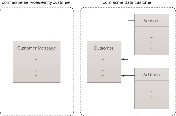
This version of the Customer class goes into the same package as the service interface to which it belongs. Following the Customer entity service example, this package can be called com.acme.services.entity.customer, although ...Domain and ...Message can be appended to their class names to make the distinction between the domain entity and message entity more explicit. Keeping the domain entity and message entity in separate packages often helps prevent naming collisions.
The set of classes representing the physical data model and the messages exposed by the new service share no technical dependencies, as they exist in separate Java packages shown in Figure 9.5. The implementation of the service ties these two sets of classes together.
Designing Stateless Entity Services
The access modes that exist for technical interfaces and influence transactional characteristics of data manipulation are typically not exposed at the entity service interface level. Entity services promote a disconnected data access mechanism and generally do not store any information about individual service consumers between service invocations. They are ideally stateless with respect to individual service consumers, and do not offer any operations that would require storage of state.
For example, it may be undesirable for entity services to offer a load or save operation because those operations would imply that a service consumer could start conversational interactions with the service.
Designing Business-Relevant Entity Services
An important consideration of entity service design that can relate to the design of any service type is ensuring that the capabilities or exposed operations carry a certain level of business semantics.
The business semantics can be seen in the naming of operations, as these names should not expose any of the technical details of the underlying implementation. Ensuring business-relevant entity services means that, for example, they should not include operations named executeCustomerQuery or loadCustomerTable, and instead should have operations named getCustomerAddress or findCustomerByAccountNumber.
Designing Generic Entity Services
Using concrete types is generally recommended on a service interface to ensure that the service contract is not ambiguous with respect to the types of messages supported. The same is true for entity services. However, certain situations require a more generic interface, such as when a service has many different service consumers with many different requirements for the messages they expect to exchange with the service.
For example, assume that an insurance company uses the Association for Cooperative Operations Research and Development (ACORD) industry standard to build a part of its enterprise data model. This standard defines large and complex data types, which in many cases provide much more information than any single service consumer requires.
The insurance company designs a service that offers vehicle information across the enterprise. The vehicle domain entity is modeled after the standard ACORD definition. Many service consumers may require vehicle information, but each of them requires a different subset of the attributes available in the domain entity.
In order to avoid defining a specific message entity for each service consumer, a single message entity can be defined to hold different sets of attributes, which depend on the attributes retrieved by a particular service consumer. The names of the attributes requested are encoded in the request message, and the entity service implementation collects the appropriate array of attributes accordingly. The message entity stores generic arrays of attributes instead of concrete attributes.
A strongly typed Vehicle message entity class is seen in Example 9.1.
package com.acme.services.entity.vehicle;
public class Vehicle {
public String VIN;
public java.util.Calendar year;
public String make;
public String model;
public String cylinders;
...
}
A more generic version of the Vehicle class is provided in Example 9.2.
package com.acme.services.entity.vehicle;
public class Vehicle {
public String VIN;
public java.util.Calendar year;
public String[] furtherInfo;
...
}
The service consumer and the entity service must agree on what kind of data is exchanged without exposing the method in the service interface. Messages parsed and evaluated at runtime run the risk of unpredictable errors, and circumventing Java’s type safety has consequences. Another example scenario that utilizes generic message entities includes a frequently changing structure of data offered by an entity service. The effect of constant changes in the data model can be minimized by making the interface more generic, although generalizing the interface delegates the change in the data model to the implementation.
Designing Aggregating Entity Services
The data exposed by an entity service can stem from a variety of sources. Message entities are shallow, or flattened, representations of this distributed domain data. Some data elements can be stored redundantly across multiple sources, requiring the entity service to maintain the appropriate relationships between the data and the data source. Datasets from different sources will likely carry different identifiers or primary keys, and the entity service must create the necessary correlation between keys for the data elements aggregated.
During the design of the entity service, establish which primary keys are required to obtain the data for the service interface, as well as how these keys relate to each other and to any foreign keys that may exist. For example, a bank’s Customer table can include an array of Account identifiers to indicate the accounts this customer has with a bank. However, these identifiers may not be usable directly as primary keys for retrieving account data from the Accounts table, and a translation can be necessary. Therefore, a correlation set shows the relationship between identifiers for accounts as contained in the Customer table. The identifiers used in the Accounts table must be designed.
Entity Service Implementation
One aspect of designing the relevant Java interfaces for an entity service is the separation between domain entities and message entities, each of which are represented by their own interfaces in their own packages. Specific and generic types used on the service interface must be business-relevant. The following section will explore the ways in which the interfaces are implemented in Java, which are dependent on the Java edition used.
Java Editions
There are two main approaches to accessing and handling data when using standard Java APIs that depend on whether or not a Java EE environment is utilized.
Java SE implements the Java Database Connectivity (JDBC) standard, which consists of two levels of API for applications and database drivers. The API for applications provides a set of classes and interfaces for manipulating and querying data from a relational database.
The java.sql.Statement interface offers a number of execute... methods allowing SQL statements to execute on the target database. With the executeQuery method, the resulting data is returned in the form of a java.sql.ResultSet with rows of data that can then be retrieved individually.
An entity service with an implementation based on the JDBC can utilize the Java API application classes to retrieve and copy relevant data from a database into the appropriate domain and message entity objects. The mapping from a relational table into a Java object must be done manually. The code must ensure that an attribute in the Java class exists for each column of the table and that the Java attribute types are consistent with their respective database column types.
Before data can be retrieved from a database using the JDBC, a connection to that database must be made. The java.sql.Connection interface, which has specific implementations for each JDBC driver, can create a connection and specify the methods responsible for committing or rolling back any transactions against the database.
Despite the seeming simplicity of the Connection API, the code must handle a wide variety of conditions and situations, including partial loading and scrolling of data, caching of both database connections and data, maintaining relationships between objects, and mapping between relational and Java types.
Complicating the implementation can hinder testing and maintenance over time. The JPA has many features evolved as part of popular open-source frameworks to resolve the code conditions for implementation. While this API was originally intended for Java EE, its reference implementation also functions in Java SE. Persistent objects are POJOs provided by the JPA that expose persistent objects via the interface of the entity service, without creating unwanted dependency on other interfaces and classes. The @Entity annotation is the only requirement to designate the classes as persistent. Additional annotations are available for storing more information in a persistent class, such as the correspondence between attributes and keys or columns in a relational table.
The JPA provides a standard for object-relational mapping, including the definition of relationships between objects. For example, assume that a Customer object has an Address object and one or more Account objects. The underlying relational model can be defined via the appropriate annotations, including the foreign key relationships between the tables for Customer, Address, and Account. Ownership relationships can be described to, for example, remove the Address object automatically whenever its owning Customer object is deleted.
In the JPA, the javax.persistence.EntityManager interface is used to read and/or write data to and from a database. The interface contains methods for finding entities, which are persistent objects in the JPA, and managing their lifecycle during transactions. Each persistent object is associated with a persistence context, and through this context the EntityManager instance manages the individual entities. The EntityManager also allows queries to be run against the database.
Queries can either be pre-defined via annotations in the entity class or dynamically built at runtime. The supported query language is an extension of the old EJB Query Language. Dealing with persistent entities in the JPA is similar to calling methods on any Java object. All aspects of persistence, such as loading and storing of data from database tables, are handled implicitly under the covers or by calling the appropriate method on the EntityManager.
Apart from managed entities which are managed by persistence context, the JPA also supports detached entities, which are not managed but tracked for changes by the persistence context. Any changes made to a detached entity would not be persisted to the database until the detached entity is brought back under the control of a persistence context or turned into a managed entity. Reintegrating a detached entity back into a persistence context is known as merging.
Versions of J2EE predating Java EE 5 (and JPA) did not support detached entities, and so developers created DTOs that wrap persistent entity EJBs so that repeated fine-grained remote calls to the entity EJBs are avoided. The introduction of detached entities in the JPA has negated the prior need to create DTOs, although use of DTOs as wrappers around the domain entities is recommended to avoid exposing the domain entities to the service consumers. DTOs help insulate the service consumers from underlying data schema changes a nd, if needed, can expose only a certain subset of the domain data to the end user.
A persistent entity can be accessed from multiple concurrent transactions, which creates the possibility of concurrent updates to the same entity that result in lost or conflicting data updates. The JPA offers various locking modes to mitigate such risks. With optimistic locking, a persistent entity can be accessed from concurrently running transactions. When changes are written back to the database, any collision is detected by the runtime and an OptimisticLockException is thrown to roll back the attempted update. A simple version field-based annotation on the entity is sufficient to detect conflicting updates.
Optimistic locking is a useful technique to reduce the risks of stale updates when detached entities are modified outside of a transaction and subsequently merged back into a managed entity. JPA 2.0 also supports pessimistic locking, which implements a write lock while reading an entity in the middle of a transaction and ensures that no other concurrent transactions can update the same entity simultaneously. However, maintaining a transactional session during a potentially long entity update is a questionable design decision. Employing pessimistic locking in such situations can result in poor scalability because of the possibility of bottlenecks or deadlocks. Pessimistic locking is useful for certain high-frequency, concurrent update scenarios in which the cost of recovering from numerous failed optimistic concurrency conflicts can outweigh the locking delays incurred in pessimistic locking.
The JPA is the core persistence API underneath the latest standards for EJBs, such as EJB 3.x. Entity beans are based on POJOs with the @Entity annotation, as per the JPA. However, no deployment descriptor forces descriptions of attributes and relationships in XML. Also, home interfaces are not required to obtain access to a persistent instance or to run a query. Finally, no JNDI lookup is needed, as all access goes through the local EntityManager instance.
In previous versions of J2EE, accessing persistent entity beans directly from a client was not recommended even though persistent entity EJBs were accessible over the network. Access directly from a client often led to excessive network traffic, because the object remained on the server and each call to a method, such as GET, had to go across the network. The recommended approach was to utilize a stateless session bean as a façade to return complete transfer objects to the client. The same practice applies when using EJB 3.x and the JPA. The persistent entity objects are accessed exclusively via a façade session bean that will send data transfer objects to its clients.
As a result, the service implementation class becomes a stateless session bean that obtains an instance of EntityManager to retrieve data when needed in support of its interface. The interface of the stateless session bean matches the service interface. Figure 9.6 illustrates how the entity service is implemented as a stateless session bean that leverages the JPA EntityManager to manage persistent data instantiated in the form of entity EJBs.
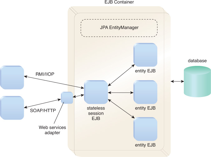
The stateless session EJB façade can be exposed over several protocols, such as RMI/IIOP or via SOAP or REST services using a Web services adapter. Beginning with Java EE 6, REST entity services implementing resources as stateless session beans should take advantage of the transactional facilities offered by the container, as opposed to a non-EJB JAX-RS resource where transactions are handled by the developers themselves.
The implementation of an entity service should take advantage of the JPA and avoid accessing the database directly or using the JDBC API. Any JPA service implementation is offered support for caching and transactions that avoid manual implementation. If utilizing Java EE, the implementation class will often be a stateless session bean that acts as a façade on top of the persistent entities managed by the JPA.
Entity Services as Web-Based Services
Regardless of whether SOAP or REST is used to build Web-based entity services, certain design considerations concerning message entities and domain entities remain applicable.
The difference between domain entities and message entities becomes even more significant when Web services are used, because the service consumer and service exist in different processes and messages must travel via a network. Pass-by-value semantics apply, and data is copied from one participant to another instead of being passed by reference.
Creating message entities that are shallow and contain only a subset of the attributes and relationships of the respective domain entities ensures superior service performance.
The entity service interface should be as coarse-grained as possible, especially when the service is deployed as a Web service. Creating these services as wrappers around each defined domain entity, or defining them for each business object used in an existing application, is not a recommended approach. Instead, service interfaces should be identified and specified beginning with a decomposition of core business processes top-down, which facilitates defining them in a coarse-grained way that offers improved performance when implemented.
Entity Web Services Using SOAP
When a data model only exists as a relational model, Java classes can be generated from the relational model using the JPA. The appropriate XML schema can then be created from those Java classes. The design of the entity service can start with Java so that the XML schema is generated depending on how the data model is developed, as seen in Figure 9.7.

When the data model is based on industry standards, which are almost exclusively developed in XML schema language, JAXB and its tools can be used. For example, the ACORD standard defines common data types for the insurance industry. In cases where the ACORD schema is the basis for an enterprise-wide data model, the xjc tool included with any JAXB implementation can be used to generate Java classes for use in the respective entity services.
There is a direct relationship between Java package names and XML namespaces. Even though the exact JAXB mapping between the package name and the XML schema namespace can be individually configured, the default is acceptable in most cases. Consider the message entity package example where message entities would go into the com.acme.services.entity.customer package. This name maps to a namespace of http://customer.entity.services.acme.com in the XML schema.
A namespace definition of http://entity.services.acme.com/customer maps to the same Java package. When using an industry standard schema, defining a different mapping from the default can allow for adherence to the specific conventions of Java package names.
Entity services based on the JPA can be implemented by either a JavaBean or stateless session EJB. Exposing a JavaBean as a Web service is addressed by the JAX-WS standard API, and exposing the stateless session EJB is defined in JSR 109 Web Services for Java EE. The JSR 109 positioned on top of the JAX-WS adds definitions that are required if the service implementation runs in a Java EE container.
There is no difference in using a JavaBean over a stateless session EJB for the service consumer. For services, a stateless session bean requires a Java EE-compliant runtime environment, which offers many additional features that are not available in a standard Java environment. Service implementations based on stateless session beans can take full advantage of those features. Significant to entity services are the transactional capabilities of EJBs, which allow implicit definition of the transactional characteristics of each instance.
Stateless session EJB instances that are automatically pooled undergo a defined lifecycle, which allows for the reuse of instances across multiple clients. The use of stateless session beans offers advantages over plain JavaBeans, because they exist in a functionally richer environment that allows the developer to focus more on the service logic. Alternatively, a standard Java environment requires less support from the underlying runtime and is generally more lightweight. However, the advent of Java EE 5 promotes a lightweight EJB model.
Stateless session beans are ideal for use as the implementation type for a Web service because service implementations also typically need to be stateless. The same is true when using JavaBeans to implement a service, as the JavaBean is created within a Web container at runtime and each service consumer invocation of the service is executed in its own thread.
Maintaining data in a service instance across invocations is at times unavoidable. Techniques to maintain data without creating unwanted side effects include storing data for individual threads only, exchanging keys to session-oriented data with a service consumer for resolution each time a new message arrives, and synchronizing access to state within the service implementation class.
Reducing the cached state in an entity service implementation class to a minimum is recommended, because the great reuse potential of these services might lead to a rather large number of concurrently active instances. The same is true for any other resources used by a service implementation, such as database connections.
REST Entity Services
REST entity services require identifying the right resources on which the HTTP operations will be invoked. Modeling the domain entities as resources is insufficient and overlooks the following considerations:
• Do the domain entities require read-only or read-write permission? If the same domain entity must offer both views, should they be modeled as different resources?
• How is varying granularity of the same domain entity handled? For service consumers interested in different subsets of the same domain entity information, should the same domain entity be modeled as different resources?
• How are new domain entities created? How does a service consumer of an entity service locate a newly created resource, possibly with a view of updating the same resource later on?
• How are service consumers expected to discover related domain entities? Can all the related entities or URI addresses be discovered dynamically, or are they required beforehand?
• How are collections of domain entities managed? Should the entire collection be modeled as a resource? How is a subset of a collection of domain entities returned to a service consumer?
• How are entity services that retrieve information from multiple domain entities in a single operation handled? What resources can be used to represent the aggregate information?
The remainder of this section provides design guidance when establishing REST entity services and concludes with a SmartCredit case study example to illustrate the design strategies applied and implemented using the JAX-RS API.
Read-Only and Read-Write Resources
Certain domain entities often only have read-only access as the entities themselves are rarely updated. An example is the category of data known as reference data, such as product codes and currency codes. For read-only entities, REST services can be built by modeling resources that only support a subset of the HTTP interface, such as GET and HEAD. Domain entities that support reads and writes can be modeled as typical resources supporting all the HTTP methods.
However, a domain entity may be scattered across multiple systems, such as databases, legacy systems, and ERP systems. Up-to-date entity information can only be obtained by performing potentially expensive queries against all source systems, which is undesirable and often unnecessary. In such situations, the complete domain entity may be assembled and refreshed only once during a 24-hour cycle, such as during a batch run at night.
A read-only view of information can be offered out of an operational data store (ODS) to requesting service consumers who do not necessarily need the most up-to-date entity information. The same domain entity can be modeled as a read-only variant supporting only GET, and as a read-write variant supporting PUT and POST.
Resource Granularity
The same domain entity may need to offer different subsets of information to different service consumers. The entity can be modeled as a single resource, and return the complete set of information for service consumers to pick the attributes of interest. However, for large datasets that can contain numerous connected resources, a more flexible, albeit complex, option can be used to model the same entity as multiple resources offering different views in different use cases.
Resource Creation and Location
All entity services that create new resources must return the URI of the newly created resources so that entity service consumers can use this information for subsequent operations. All resources must be addressable, so the address of a newly created resource must be communicated. Example 9.11 illustrates the creation of a resource.
Request Message
POST /customers HTTP/1.1
Content-Type: application/xml
<customer>
<first-name>John</first-name>
<last-name>Doe</last-name>
...
</customer>
Response Message
HTTP/1.1 201 Created
Content-Type: application/xml
Location:http://server/services/customers/1234
<customer id="1234">
...
</customer>
Example 9.11 A John Doe request/response example of entity services for a newly created resource
In Example 9.11, the entity service for creating a customer accepts a POST request and returns a response with an HTTP Location header, which indicates the URI address of the newly created customer resource. Example 9.12 revisits the example from Chapter 6 where a customer was created from a CustomerResource class within a JAX-RS resource.
import javax.ws.rs.core.*;
...
@POST
@Consumes("application/xml")
public Response createCustomer(Customer cust) {
//...create customer in the system
String baseURI = ...;
Customer c = createCustomer(cust);
return Response.created(java.net.URI.create(
baseURI+c.getCustomerId()).entity(c).build();
}
The JAX-RS javax.ws.rs.core.Response.created method returns an HTTP 201 response Created with a Location header carrying the URI of the newly created resource. The Response.created method returns a javax.ws.rs.core.Response-Builder object, which can be chained with the ResponseBuilder.entity method passing in any java.lang.Object as the returned entity. Apart from the 201 status code with a Location header, a resource representation is returned to the newly created customer. The mapping of the JAXB object to the XML resource representation is handled by the JAX-RS runtime.
Resource Relationships
Most domain entities participate in a web of relationships, such as “an order entry may have multiple order items,” and “an order item may have a number of suppliers associated with it.” If the creation of an order is to be modeled as an entity service, the service consumer must be able to discover information about the order items. The relationship between resources in a resource representation is best described through links.
A link has an associated URI address that service consumers can use to navigate to a related resource. Describing a link in a way that non-human service consumers can interpret and act upon is important for the service consumer to be able to understand the semantics of the link. Embedding a custom element, such as <uri>, in a resource representation can be intuitive enough for human service consumers, but an application must know what <uri> signifies.
The Atom syndication format provides standardized link elements and a relation attribute that can take on a range of well-known values for interpretation by an Atom link-aware service consumer application, as seen in Example 9.13.
Request Message
POST /orders HTTP/1.1
Content-Type: application/xml
<Order>
...
</Order>
Response Message
HTTP/1.1 201 Created
Content-Type: application/xml
Location:http://server/services/orders/333
<order id="1234">
...
<orderitem id="456">
<atom:link rel="self" href=http://server/services/orderitems/456
type="application/xml"/>
...
</orderitem>
</order>
GET orderitems/456 HTTP/1.1
Content-Type: application/xml
...
The Atom link element’s href attribute in Example 9.13 specifies the URI and indicates the location of the order item resource. The value of the relation attribute indicates the link represents the preferred address of the resource, and the type attribute describes the resource representation format.
The hypermedia constraint enables service consumers to discover and navigate to linked resources via standardized means, such as Atom links. In resource representations, such types of links are known as structural links that encapsulate other aggregate entities. Structural links are embedded in the same location as the aggregating entity.
Resource Collections
Entity services must often return a collection of domain entities based on set criteria. To find all orders priced over 1,000 dollars, the collection of orders can be modeled as a resource and issue a GET operation to filter the results, as seen in Example 9.14.
Request Message
GET /orders?minimum=1000 HTTP/1.1
Content-Type: application/xml
...
Response Message
HTTP/1.1 200 ok
Content-Type: application/xml
<orders>
...
<order id="444">...</order>
<order id="666">...</order>
<!— more orders, possibly thousands... -->
</orders>
The result of the GET operation produced orders with unnecessary information. To navigate through the list ten orders at a time, adding the additional query parameters:
GET /orders?minimum=1000&start=1&size=10
...increases the coupling between the service consumer and service by requiring the service consumer to know and pass in additional information beyond what is part of the service interface, such as the start and size information as opposed to the minimum order value. Transitional links, which are based on RFC 5988 that leverage HTTP headers with the link header fields, can be used to resolve the increased coupling. A new HTTP link header field in the response can point to the next allowed state transition of the resource, as in Example 9.15.
HTTP/1.1 200 ok
Content-Type: application/xml
Link: <http://server/services/orders?minimum=1000&start=1&size=10>;
rel=next
<orders>
<order id="444">...</order>
<order id="666">...</order>
<!— ...8 more orders in the current batch of 10... -->
</orders>
The client follows the link in the link header to request the next set of resources and the response changes, as highlighted in Example 9.16.
HTTP/1.1 200 ok
Content-Type: application/xml
Link: <http://server/services/orders?minimum=1000&start=11&size=10>; rel=next
<orders>
<order id="4444">...</order>
<order id="6666">...</order>
<!— ...8 more orders in the current batch of 10... -->
</orders>
The RFC 5988 link relation attribute rel=next refers to the next resource in an ordered set of resources. A transitional link-aware client can correctly interpret the relation attribute value and discover the URI pointing to the next resource set, which reinforces the hypermedia-driven navigation constraint.
The JAX-RS 2.0 APIs support transitional links through the javax.ws.rs.core.Link class, and a Link header can be embedded along with the response via the call listed in Example 9.17.
List<Order> orders = getNextOrders();
//getNextOrders returns a batch of orders
Response resp = Response.ok(orders).link("http://server/services/orders?minimum=1000&start=1&size=10", "next").build();
Instead of moving the query parameters inside the attribute of an Atom link element, the value of the relation attribute of the link element next points to the next set of resources in an ordered collection of resources. An Atom-aware client can correctly interpret the relation attribute value and discover the URI of the next set of resources in the collection without requiring any additional information beforehand.
Aggregate Entities
Domain entities often participate in complex relationships, and use cases often demand aggregating information from multiple domain entities. The level of details in the aggregate entity may not capture all of the fine-grained attributes of all the related entities, but rather present summary-level information spanning the entities. For example, a Customer Account Summary service retrieves customer account balances from all of the account holdings. The summary information is an aggregate of various disparate attributes, such as customer id, name, account type, description, and account balances that span multiple entities, such as customer and account.
Modeling a REST service for retrieving the summary information must capture both customer and account resource states. If the client is left to retrieve individual bits of information from multiple entities, such as customer and account information, not only is traffic increased over the network, but internal implementation details of how the customer account summary information is obtained are also exposed to the service consumer.
An alternative is to offer an aggregate entity, such as a Customer Summary, that can provide the requested information via an HTTP GET operation and avoid multiple network trips while hiding the internal implementation details of how individual account attributes are retrieved, as seen in Example 9.18.
Request Message
GET /customersummary/5678 HTTP/1.1
Response Message
HTTP/1.1 200 ok
Content-Type: application/xml
<customersummary xmlns:atom="http://www.w3.org/Atom/2005">
<customer id="5678">
<atom:link rel="self"
href="http://server/services/customer/5678"/>
<name>John Doe</name>
...
</customer>
<accounts>
<atom:link rel="http://server/services/custaccts"
href="http://server/services/accounts?customerid=5678"/>
<account id="666" type="chk">
<balance>500</balance>
...
</account>
<account>
...
</account>
...
</accounts>
</customersummary>
Example 9.18 An aggregate entity provides the Customer Summary service information via an HTTP GET operation.
Structural links are embedded to enable discovery of related resources, such as a collection of related accounts. The value of the rel attribute for the accounts resource points to a URI. Instead of referring to another resource location, the URI is an Atom link relation extension identifying the purpose of the link via a URI without any guarantee that this URI resolves to a locatable resource.
The Collection of Accounts resource can be located at the URI indicated by the atom:link href attribute. A link relation extension is used with a custom value for the rel attribute because the standard values of the rel attribute, such as "self" and "alternate," are inapplicable in this case. In terms of updates to an aggregate resource, the service consumers should not be allowed to update a customer summary, transfer the balance from the checking account to a savings account, or deactivate the checking account, as seen in Example 9.19.
PUT /customersummary/5678 HTTP/1.1
Content-Type:application/xml
<customersummary>
<!- ...transfer checking account balance,
cancel checking...-->
</customersummary>
Aggregate resources assemble information from various resources but should not be the vehicle to update or create any of their constituent resources, as the update operations should be handled by the individual resources. The response to the request to alter the customersummary from Example 9.19 is presented in Example 9.20.
HTTP/1.1 405 Method Not Allowed
Allow: GET, HEAD
The response indicates the invoked operation is Not Allowed on this resource, and the Allow header indicates that the only allowed operations are GET and HEAD.
Open-Source Frameworks
Many Java developers preferred to utilize persistence frameworks built on top of the standard Java support. These frameworks leverage existing APIs such as the JDBC, but offer more convenient methods of handling persistent data that include mapping to Java classes and objects.
In the open-source space, a common framework for persistence is Hibernate. Many of its features heavily influenced the design of the Java Persistence API. Hibernate implements the Java Persistence API and can act as a persistence service in any Java EE-compliant application server.
Testing Considerations
Entity services can introduce special considerations for testing. For example, service consumers can utilize an entity service in a synchronous online fashion, which requires fast response times and high availability. Other service consumers could use an entity service in a more batch-oriented asynchronous manner, in which many transactions requiring high throughput with less stringent response time requirements are handled.
These different usage profiles all require testing, both individually and in concert. For example, the response time of a particular entity service should function normally if heavy streams of requests by a batch service consumer are received. Heavy batch processing can result in multiple instances of the service being deployed to isolate certain service consumers from affecting each other. Such deployment needs are identified through frequent and early testing of the performance characteristics of any given entity service.
High service reuse accompanies a high degree of concurrency for consideration. An entity service accessed simultaneously by many different service consumers requires thorough testing for side effects that may hinder or impede functionality, such as data changed by a service consumer and whether optimistic locking is used. Each service must implement a specific optimistic strategy for situations where the same data is updated by different service consumers at the same time. Simultaneous saved changes to the data can nevertheless be written to a persistent data store, or result in an error signaled back to the servi ce consumer. Testing will ensure functionality regardless of the implemented strategy.
When data is aggregated from multiple sources, the performance of the overall service is defined by the combined performance characteristics of every accessed data source. In many cases, aggregated entity services are more susceptible to performance problems that require appropriate testing.
Java Packaging Considerations
Code artifacts related to domain entities and message entities should be packaged separately with no direct dependency on each other. Sometimes domain entities have no code artifacts to begin with. Classes and interfaces for message entities should be packaged with the entity service implementation classes, as they are tightly coupled and not reused across several service implementations.
For deployment into a Java EE runtime environment, the service implementation classes and the message entity classes go into the same enterprise archive (EAR) application module. Message entities can be packaged as a utility jar file or be directly included in the EJB module containing the EJB classes for the service. Domain entity classes and interfaces are packaged in a separate utility jar file for reuse across multiple services if they are leveraged in the service implementation.
Note that packaging entity services separately can result in a large number of enterprise applications in cases where many entity services are defined. Having a Java EE environment handle large numbers of applications can result in maintenance challenges if certain procedures and process steps must be applied to each enterprise application. For example, grouping several entity services into one enterprise application to install updated applications can be reasonable under time constraints. The enterprise application can group entity services based on their associated business domains.