
Chapter 4. I/O Processing
This chapter continues the discussion of inputs and outputs from Chapter 2 and is a brief consideration of the processing of the signals from input and output devices. The input/output (I/O) unit provides the interface between the PLC controller and the outside world and must therefore provide the necessary signal conditioning to get the signal to the required level and also to isolate it from possible electrical hazards such as high voltages. This chapter includes the forms of typical input/output modules and, in an installation where sensors are some distance from the PLC processing, their communication links to the PLC.
4.1. Input/Output Units
Input signals from sensors and outputs required for actuating devices can be:
• Analog. A signal for which the size is related to the size of the quantity being sensed.
• Discrete. Essentially just an on/off signal.
• Digital. A sequence of pulses.
The CPU, however, must have an input of digital signals of a particular size, normally 0 to 5 V. The output from the CPU is digital, normally 0 to 5 V. Thus there is generally a need to manipulate input and output signals so that they are in the required form.
The input/output (I/O) units of PLCs are designed so that a range of input signals can be changed into 5 V digital signals and so that a range of outputs are available to drive external devices. It is this in-built facility to enable a range of inputs and outputs to be handled that makes PLCs so easy to use. The following is a brief indication of the basic circuits used for input and output units. In the case of rack instruments, they are mounted on cards that can be plugged into the racks, and so the input/output characteristics of the PLC can thus be changed by changing the cards. A single box form of PLC has input/output units incorporated by the manufacturer.
4.1.1. Input Units
The terms sourcing and sinking refer to the manner in which DC devices are interfaced with the PLC (see Section 1.3.5). For a PLC input unit, with sourcing, it is the source of the current supply for the input device connected to it (Figure 4.1a). With sinking, the input device provides the current to the input unit (Figure 4.1b).

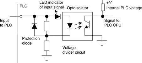
Figures 4.2 and 4.3 show the basic input unit circuits for DC and AC inputs. Optoisolators (see Section 1.3.4) are used to provide protection. With the AC input unit, a rectifier bridge network is used to rectify the AC so that the resulting DC signal can provide the signal for use by the optoisolator to give the input signals to the CPU of the PLC. Individual status lights are provided for each input to indicate when the input device is providing a signal.

With analog signals inputted to a PLC, the input channel needs to convert the signal to a digital signal using an analog-to-digital converter. With a rack-mounted system this may be achieved by mounting a suitable analog input card in the rack. So that one analog card is not required for each analog input, multiplexing is generally used (Figure 4.4). This involves more than one analog input being connected to the card and then electronic switches used to select each input in turn. Cards are typically available giving 4, 8, or 16 analog inputs.
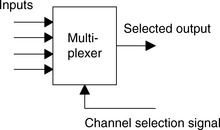
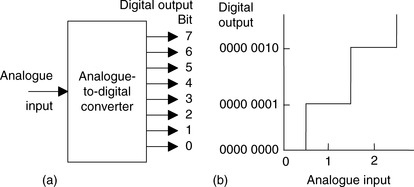
Figure 4.5a illustrates the function of an analog-to-digital converter (ADC). A single analog input signal gives rise to on/off output signals along perhaps eight separate wires. The eight signals then constitute the so-termed digital word corresponding to the analog input signal level. With such an 8-bit converter there are 28 = 256 different digital values possible; these are 0000 0000 to 1111 1111, that is, 0 to 255. The digital output goes up in steps (Figure 4.5b) and the analog voltages required to produce each digital output are termed quantization levels.
 |
| Figure 4.5 |
If the binary output is to change, the analog voltage has to change by the difference in analog voltage between successive levels. The term resolution is used for the smallest change in analog voltage that will give rise to a change in 1 bit in the digital output. With an 8-bit ADC, if, say, the full-scale analog input signal varies between 0 and 10 V, a step of one digital bit involves an analog input change of 10/255 V or about 0.04 V. This means that a change of 0.03 V in the input will produce no change in the digital output. The number of bits in the output from an analog-to-digital converter thus determines the resolution, and hence accuracy, that is possible. If a 10-bit ADC is used, then 210 = 1024 different digital values are possible and, for the full-scale analog input of 0 to 10 V, a step of one digital bit involves an analog input change of 10/1023 V, or about 0.01 V. If a 12-bit ADC is used, then 212 = 4096 different digital values are possible and, for the full-scale analog input of 0 to 10 V, a step of one digital bit involves an analog input change of 10/4095 V, or about 2.4 mV. In general, the resolution of an n-bit ADC is 1/(2n – 1); this is sometimes approximated to 2–n.
The following illustrates the analog-to-digital conversion for an 8-bit converter when the analog input is in the range 0 to 10 V:
| Analog Input (V) | Digital Output (V) |
|---|---|
| 0.00 | 0000 0000 |
| 0.04 | 0000 0001 |
| 0.08 | 0000 0010 |
| 0.12 | 0000 0011 |
| 0.16 | 0000 0100 |
| 0.20 | 0000 0101 |
| 0.24 | 0000 0110 |
| 0.28 | 0000 0111 |
| 0.32 | 0000 1000 |
| etc. |
To illustrate this idea, consider a thermocouple used as a sensor with a PLC and giving an output of 0.5 mV per °C. What will be the accuracy with which the PLC will activate the output device if the thermocouple is connected to an analog input with a range of 0 to 10 V DC and using a 10-bit analog-to-digital converter? With a 10-bit converter, there is 210 = 1024 bits covering the 0 to 10 V range. Thus a change of 1 bit corresponds to 10/1023 V or about 0.01 V, that is, 10 mV. Hence the accuracy with which the PLC recognizes the input from the thermocouple is ±5 mV or ±10°C.
Conversion from analog to digital takes time and, in addition, the use of a multiplexer means that an analog input card of a PLC only takes “snapshot” samples of input signals. For most industrial systems, signals from plant rarely vary so fast that this presents a problem. Conversion times are typically a few milliseconds.
4.1.2. Output Units
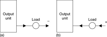
With a PLC output unit, when it provides the current for the output device (Figure 4.6a) it is said to be sourcing, and when the output device provides the current to the output unit, it is said to be sinking (Figure 4.6b). Quite often, sinking input units are used for interfacing with electronic equipment and sourcing output units for interfacing with solenoids.
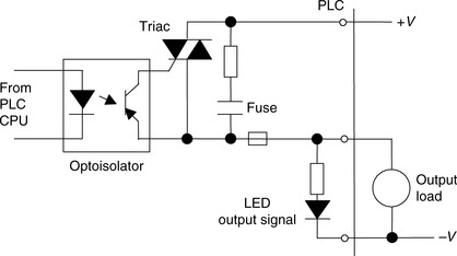
Output units can be relay, transistor, or triac. Figure 4.7 shows the basic form of a relay output unit, Figure 4.8 that of a transistor output unit, and Figure 4.9 that of a triac output unit.


Analog outputs are frequently required and can be provided by digital-to-analog converters (DACs) at the output channel. The input to the converter is a sequence of bits with each bit along a parallel line. Figure 4.10 shows the basic function of the converter.

A bit in the 0 line gives rise to a certain size output pulse. A bit in the 1 line gives rise to an output pulse of twice the size of the 0 line pulse. A bit in the 2 line gives rise to an output pulse of twice the size of the 1 line pulse. A bit in the 3 line gives rise to an output pulse of twice the size of the 2 line pulse, and so on. All the outputs add together to give the analog version of the digital input. When the digital input changes, the analog output changes in a stepped manner, the voltage changing by the voltage changes associated with each bit. For example, if we have an 8-bit converter, the output is made up of voltage values of 28 = 256 analog steps. Suppose the output range is set to 10 V DC. One bit then gives a change of 10/255 V or about 0.04 V. Thus we have:
| Digital Input (V) | Analog Output (V) |
|---|---|
| 00000000 | 0.00 |
| 00000001 | 0.04 |
| 00000010 | 0.08 + 0.00 = 0.08 |
| 00000011 | 0.08 + 0.04 = 0.12 |
| 00000100 | 0.16 |
| 00000101 | 0.016 + 0.00 + 0.04 = 0.20 |
| 00000110 | 0.016 + 0.08 = 0.24 |
| 00000111 | 0.016 + 0.08 + 0.04 = 0.28 |
| 00001000 | 0.32 |
| etc. |
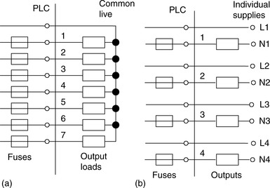
Analog output modules are usually provided in a number of outputs, such as 4 to 20 mA, 0 to +5 V DC, and 0 to +10 V DC, and the appropriate output is selected by switches on the module. Modules generally have outputs in two forms, one for which all the outputs from that module have a common voltage supply and one that drives outputs with their own individual voltage supplies. Figure 4.11 shows the basic principles of these two forms of output.
4.2. Signal Conditioning
When connecting sensors that generate digital or discrete signals to an input unit, care has to be taken to ensure that voltage levels match. However, many sensors generate analog signals. To avoid having a multiplicity of analog input channels to cope with the wide diversity of analog signals that can be generated by sensors, external signal conditioning is often used to bring analog signals to a common range and so allow a standard form of analog input channel to be used.
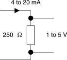
A common standard that is used (Figure 4.12) is to convert analog signals to a current in the range 4 to 20 mA and thus to a voltage by passing it through a 250 Ω resistance to give a 1 to 5 V input signal. Thus, for example, a sensor used to monitor liquid level in the height range 0 to 1 m would have the 0 level represented by 4 mA and the 1 m represented by 20 mA. The use of 4 mA to represent the low end of the analog range serves the purpose of distinguishing between when the sensor is indicating zero and when the sensor is not working and giving zero response for that reason. When this happens the current would be 0 mA. The 4 mA also is often a suitable current to operate a sensor and so eliminate the need for a separate power supply.
4.2.1. Changing Voltage Levels
A potential divider (Figure 4.13) can be used to reduce a voltage from a sensor to the required level; the output voltage level Vout is:

Amplifiers can be used to increase the voltage level; Figure 4.14 shows the basic form of the circuits that might be used with a 741 operational amplifier with (a) being an inverting amplifier and (b) a noninverting amplifier. With the inverting amplifier the output Vout is:
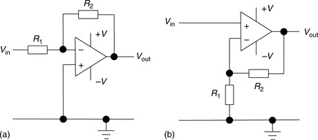
and with the noninverting amplifier:
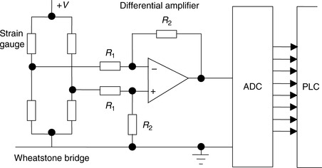
Often a differential amplifier is needed to amplify the difference between two input voltages. Such is the case when a sensor—for example, a strain gauge—is connected in a Wheatstone bridge and the output is the difference between two voltages or a thermocouple where the voltage difference between the hot and cold junctions is required. Figure 4.15 shows the basic form of an operational amplifier circuit for this purpose.
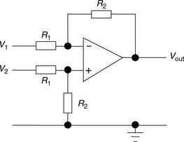
The output voltage Vout is:
As an illustration of the use of signal conditioning, Figure 4.16 shows the arrangement that might be used for a strain gauge sensor. The sensor is connected in a Wheatstone bridge and the out-of-balance potential difference amplified by a differential amplifier before being fed via an analog-to-digital converter unit, which is part of the analog input port of the PLC.
4.2.2. Op-Amp Comparator
The output of an operational amplifier saturates at about ±12 V, such outputs typically being reached with inputs of about ±10 μV. Figure 4.17 shows the basic form of the characteristic. Thus, operational amplifiers are widely used to give on/off signals based on the relative value of two input signals. One signal is connected to the noninverting terminal and the other to the inverting terminal. The operational amplifier determines whether the signal to the inverting terminal is above or below that to the noninverting terminal, that is, it is a comparator. By reversing the reference and input voltage connections, the output polarity is changed. Such comparators can be used as the basis for on/off control systems. Thus we might have a reference voltage and compare the voltage from a sensor with it and so obtain an on/off output depending on whether the voltage from the sensor is above or below the reference voltage.

4.2.3. Output Protection
Outputs involving coils of wire, such as solenoids and motors, are inductors. When there is a current, such inductors store energy in the magnetic field, and when the current is switched off, the magnetic field collapses and produces a back EMF that can be quite large. The simplest method of protection against this back EMF is to place a diode in parallel with the coil. The diode is so connected that current cannot flow through it when the current is energizing the coil but will short-circuit the coil and so suppress the current arising from the back EMF. Such a diode is often referred to as a flyback diode.
Some output devices may need series current-limiting resistors. For example, an LED display has generally a maximum current rating of about 10 to 30 mA. With 20 mA the voltage drop across it might be 2.1 V. Thus if we have an input of 5 V to it, 2.9 V has to be dropped across a series resistor. This means a series resistance of 2.9/0.020 = 145 Ω and so a standard resistor of 150 Ω might be used. Some LEDs are supplied with built-in resistors.
4.3. Remote Connections
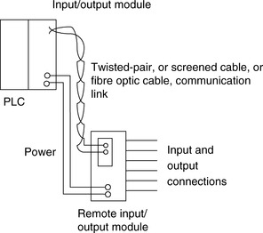
When there are many inputs or outputs located considerable distances away from the PLC, though it would be possible to run cables from each such device to the PLC, a more economic solution is to use input/output modules in the vicinity of the inputs and outputs and use just a single core cable to connect each, over the long distances, to the PLC instead of the multicore cable that would be needed without such distant I/O modules (Figure 4.18).
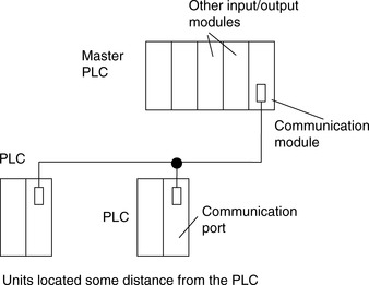
In some situations a number of PLCs may be linked together with a master PLC unit sending and receiving input/output data from the other units (Figure 4.19). The distant PLCs do not contain the control program since all the control processing is carried out by the master PLC.
The cables used for communicating data between remote input/output modules and a central PLC, remote PLCs, and the master PLC are typically twisted-pair cabling, often routed through grounded steel conduit to reduce electrical “noise.” Coaxial cable enables higher data rates to be transmitted and does not require the shielding of steel conduit. Fiber-optic cabling has the advantage of resistance to noise, small size, and flexibility and is now becoming more widely used.
4.3.1. Serial and Parallel Communications
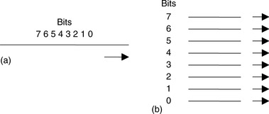
In serial communication, data is transmitted one bit at a time (Figure 4.20a). Thus if an 8-bit word is to be transmitted, the 8 bits are transmitted one at a time in sequence along a cable. This means that a data word has to be separated into its constituent bits for transmission and then reassembled into the word when received. In parallel communication, all the constituent bits of a word are simultaneously transmitted along parallel cables (Figure 4.20b). This allows data to be transmitted over short distances at high speeds.
Serial communication is used for transmitting data over long distances. It is much cheaper to run, for serial communication, a single core cable over a long distance than the multicore cables that would be needed for parallel communication. With a PLC system, serial communication might be used for the connection between a computer, when used as a programming terminal, and a PLC. Parallel communication might be used when connecting laboratory instruments to the system. However, internally, PLCs work, for speed, with parallel communications. Thus, circuits called universal asynchronous receivers/transmitters (UARTs) have to be used at input/output ports to converts serial communications signals to parallel.
4.3.2. Serial Standards
For successful serial communications to occur, it is necessary to specify:
• The voltage levels to be used for signals, that is, what signal represents a 0 and what represents a 1.
• What the bit patterns being transmitted mean and how the message is built up. Bear in mind that a sequence of words is being sent along the same cable and it is necessary to be able to determine when one word starts and finishes and the next word starts.
• The speed at which the bit pattern is to be sent, that is, the number of bits per second.
• Synchronization of the clocks at each end. This is necessary if, for example, a particular duration transmitted pulse is to be recognized by the receiver as just a single bit rather than two bits.
• Protocols, or flow controls, to enable such information as “able to receive data” or “not ready to receive data” to be received. This is commonly done by using two extra signal wires (termed handshake wires), one to tell the receiver the transmitter is ready to send data and the other to tell the transmitter the receiver is ready to receive it.
• Error-checking to enable a bit pattern to be checked to determine whether corruption of the data has occurred during transmission.
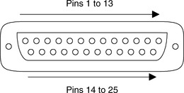
The most common standard serial communications interface is the RS232. Connections are made via 25-pin D-type connectors (Figure 4.21), usually, though not always, with a male plug on cables and a female socket on the equipment. Not all the pins are used in every application.
The minimum requirements are:
Pin 1: Ground connection to the frame of chassis
Pin 2: Serial transmitted data (output data pin)
Pin 3: Serial received data (input data pin)
Pin 7: Signal ground, which acts as a common signal return path
Configurations that are widely used with interfaces involving computers are as follows:
Pin 1: Ground connection to the frame of chassis
Pin 2: Serial transmitted data (output data pin)
Pin 3: Serial received data (input data pin)
Pin 4: Request to send
Pin 5: Clear to send
Pin 6: Data set ready
Pin 7: Signal ground, which acts as a common signal return path
Pin 20: Data terminal ready
The signals sent through pins 4, 5, 6, and 20 are used to check that the receiving end is ready to receive a signal, the transmitting end is ready to send and the data is ready to be sent. With RS232, a 1 bit is represented by a voltage between −5 and −25 V, normally −12 V, and a 0 by a voltage between +5 and +25 V, normally +12 V.
The term baud rate is used to describe the transmission rate, which is approximately the number of bits transmitted or received per second. However, not all the transmitted bits can be used for data; some have to be used to indicate the start and stop of a serial piece of data, often termed flags, and as a check as to whether the data has been corrupted during transmission. Figure 4.22 shows the type of signal that might be sent with RS232. The parity bit is added to check whether corruption has occurred, with, in even parity, a 1 being added to make the number of 1s an even number. To send seven bits of data, 11 bits may be required.

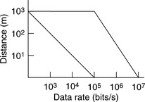
Other standards such as RS422 and RS423 are similar to RS232. RS232 is limited over the distances it can be used, noise limiting the transmission of high numbers of bits per second when the length of cable is more than about 15 m. RS422 can be used for longer distances. This method uses a balanced method of transmission. Such circuits require two lines for the transmission, the transmitted signal being the voltage difference between the two lines. Noise affecting both lines equally will have no effect on the transmitted signal. Figure 4.23 shows how, for RS232 and RS422, the data rates that can be transmitted without noise becoming too significant depend on the distance. RS422 lines can be used for much greater distances than RS232.
RS422 uses a balanced interface, employing a voltage on one line with respect to another line to define a 1 signal and the opposite polarity between the two lines to define a 0 signal. RS423 uses an unbalanced interface, involving a voltage on the line relative to a fixed voltage, usually the signal ground, to determine 1 and 0 signals. It has a line for all transmitted signals and a line for all received signals. RS423 is not as fast for transmission as RS422 but has similar distances of transmission. Some devices may be configured to provide either RS422 or RS423 interfaces.
An alternative to RS422 or RS423 is the 20 mA loop, which was an earlier standard and is still widely used for long distance serial communication, particularly in industrial systems where the communication path is likely to suffer from electrical noise (Figure 4.24). Distances up to a few kilometers are possible. This system consists of a circuit, a loop of wire, containing a current source. The serial data is transmitted by the current being switched on and off, a 0 being transmitted as zero current and a 1 as 20 mA. For two-way communications, a pair of separate wires is used for the transmission and receiver loops. The serial data is encoded with a start bit, a right data bits, and two stop bits.

Other buses that are used often in particular situations are the Inter-IC Communication, or I2C, bus, designed by Philips for use in communication between integrated circuits or modules; the Controller Area Network, or CAN, bus, developed by Bosch for the engine management systems of cars; the Universal Serial Bus, or USB, bus, designed to enable monitors, printers, and other input devices to be easily connected to computer systems; and Firewire, developed by Apple Computers to give plug-and-play capabilities with computer systems.
4.3.3. Parallel Standards
The standard interface most commonly used for parallel communications is IEEE-488. This was originally developed by Hewlett-Packard to link its computers and instruments and was known as the Hewlett-Packard Instrumentation Bus. It is now often termed the General-Purpose Instrument Bus. This bus provides a means of making interconnections so that parallel data communications can take place among listeners, talkers, and controllers. Listeners are devices that accept data from a bus; talkers place data, on request, on the bus; and controllers manage the flow of data on the bus and provide processing facilities. A bus has a total of 24 lines, of which eight bidirectional lines are used to carry data and commands between the various devices connected to the bus, five lines are used for control and status signals, three are used for handshaking between devices, and eight are ground return lines (Figure 4.25). Handshaking is the term used for the transfer of control information, such as DATA READY and INPUT ACKNOWLEDGED signals, between two devices.

Commands from the controller are signaled by taking the ATTENTION LINE (ATN) low; otherwise it is high, thus indicating that the data lines contain data. The commands can be directed to individual devices by placing addresses on the data lines. Each device on the bus has its own address. Device addresses are sent via the data lines as a parallel 7-bit word, the lowest 5 bits providing the device address and the other 2 bits providing control information. If both these bits are 0, the commands are sent to all addresses; if bit 6 is 1 and bit 7 a 0, the addressed device is switched to be a listener; if bit 6 is 0 and bit 7 is 1, the device is switched to be a talker.
As illustrated by the function of the ATN line, the management lines each have an individual task in the control of information. The handshake lines are used for controlling the transfer of data. The three lines ensure that the talker will only talk when it is being listened to by listeners. Table 4.1 lists the functions of all the lines and their pin numbers in a 25-way D-type connector.
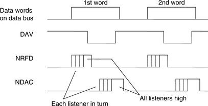
Figure 4.26 shows the handshaking sequence that occurs when data is put on the data lines. Initially DAV is high, indicating that there is no valid data on the data bus, NRFD and NDAC also being low. When a data word is put on the data lines, NRFD is made high to indicate that all listeners are ready to accept data, and DAV is made low to indicate that new data is on the data lines. When a device accepts a data word, it sets NDAC high to indicate that is has accepted the data and NRFD low to indicate that it is now not ready to accept data. When all the listeners have set NDAC high, the talker cancels the data valid signal, DAV going high. This then results in NDAC being set low. The entire process can then be repeated for another word being put on the data bus.
4.3.4. Protocols
It is necessary to exercise control of the flow of data between two devices so that what constitutes the message, and how the communication is to be initiated and terminated, is defined. This is termed the protocol.
Thus one device needs to indicate to the other to start or stop sending data. This can be done by using handshaking wires connecting transmitting and receiving devices so that a signal along one such wire can tell the receiver that the transmitter is ready to send (RTS) and along another wire that the transmitter is ready to receive, a clear-to-send signal (CTS). RTS and CTS lines are provided for in RS232 serial communication links.
An alternative is to use additional characters on the transmitting wires. With the ENQ/ACK protocol, data packets are sent to a receiver with a query character ENQ. When this character is received, the end of the data packet has been reached. Once the receiver has processed that data, it can indicate it is ready for another block of data by sending back an acknowledge (ACK) signal. Another form, the XON/XOFF, has the receiving device sending a XOFF signal to the sending device when it wants the data flow to cease. The transmitter then waits for an XON signal before resuming transmission.
One form of checking for errors in the message that might occur as a result of transmission is the parity check. This is an extra bit added to a message to ensure that the number of bits in a piece of data is always odd or always even. For example, 0100100 is even because there is an even number of 1s; 0110100 is odd because there is an odd number of 1s. To make both these odd parity, the extra bit added at the end in the first case is 1 and in the second case 0, that is, we have 01001001 and 01101000. Thus when a message is sent out with odd bit parity, if the receiver finds that the bits give an even sum, the message has been corrupted during transmission and the receiver can request that the message be repeated.
The parity bit method can detect whether there is an error resulting from a single 0 changing to a 1 or a 1 changing to a 0 but cannot detect two such errors occurring, since there is then no change in parity. To check on such occurrences, more elaborate checking methods have to be used. One method involves storing data words in an array of rows and columns. Parity can then be checked for each row and each column. The following illustrates this concept for seven words using even parity.
| Row parity bits | ||
| Column parity bits | 00101010 | 1 |
| ↑ | 10010101 | 0 |
| 10100000 | 0 | |
| Block | 01100011 | 0 |
| of data | 11010101 | 1 |
| 10010101 | 1 | |
| ↓ | 00111100 | 0 |
Another method, termed cyclic redundancy check codes, involves splitting the message into blocks. Each block is then treated as a binary number and is divided by a predetermined number. The remainder from this division is sent as the error-checking number on the conclusion of the message and enables a check to be made on the accuracy of the message.
4.3.5. ASCII Codes
The most widely used code for the transmission of characters is the American Standard Code for Information Interchange (ASCII). This is a 7-bit code giving 128 different combinations of bits covering lower- and uppercase alphanumeric characters, punctuation, and 32 control codes. As an illustration, Table 4.2 shows the codes used for capital letters. Examples of control codes are SOH, for start of heading, that is, the first character of a heading of an information message, as 000 0001; STX, for start of text, as 000 0010; ETX, for end of text, as 000 0011; and EOT, for end of transmission, as 000 0011.
4.4. Networks
The increasing use of automation in industry has led to the need for communications and control on a plant-wide basis, with programmable controllers, computers, robots, and CNC machines interconnected. The term local area network (LAN) is used to describe a communications network designed to link computers and their peripherals within the same building or site.
Networks can take three basic forms. With the star form (Figure 4.27a), the terminals are each directly linked to a central computer, termed the host or master, with the terminals being called slaves. The host contains the memory, processing, and switching equipment to enable the terminals to communicate. Access to the terminals is by the host asking each terminal in turn whether it wants to talk or listen. With the bus or single highway type of network (Figure 4.27b), each of the terminals is linked into a single cable and so each transmitter/receiver has a direct path to each other transmitter/receiver in the network. Methods, that is, protocols, have to be adopted to ensure that no more than one terminal talks at once; otherwise confusion can occur. A terminal has to be able to detect whether another terminal is talking before it starts to talk. With the ring network (Figure 4.27c), a continuous cable, in the form of a ring, links all the terminals. Again, methods have to be employed to enable communications from different terminals without messages becoming mixed up. The single highway and the ring methods are often called peer to peer in that each terminal has equal status. Such a system allows many stations to use the same network.

With ring-based networks, two commonly used methods that are employed to avoid two stations talking at once and so giving rise to confusion are token passing and slot passing. With token passing, a special bit pattern called a token is circulated round the network. When a station wants to transmit into the network, it waits until it receives the token, then transmits the data with the token attached. Another station that wants to transmit cannot do so until the token has been freed by removal from the data by a receiver. With slot passing, empty slots are circulated into which stations can deposit data for transmission.
Bus systems generally employ the method in which a system that wants to transmit listens to see whether any messages are being transmitted. If no message is being transmitted, a station can take control of the network and transmit its message. This method is known as carrier sense multiple access (CSMA). However, we could end up with two stations simultaneously perceiving the network to be clear for transmission and both simultaneously taking control and sending messages. The result would be a “collision” of their transmitted data, resulting in corruption. If such a situation is detected, both stations cease transmitting and wait a random time before attempting to again transmit. This is known as carrier sense multiple access with collision detection (CSMA/CD).
PLC manufacturers adopt different forms of network systems and methods of communication for use with their PLCs. For example, Mitsubishi uses a network termed MelsecNET, Allen-Bradley has Data Highway Plus, General Electric uses GENET, Texas Instruments uses TIWAY, and Siemens has PROFIBUS DP. Most, like Allen-Bradley, employ peer-to-peer forms. With Siemens, PROFIBUS DP is a star, that is, a master/slave form.
4.4.1. Distributed Systems
Often PLCs figure in an hierarchy of communications (Figure 4.28). Thus at the lowest level we have input and output devices such as sensors and motors interfaced through I/O interfaces with the next level. The next level involves controllers such as small PLCs or small computers, linked through a network, with the next level of larger PLCs and computers exercising local area control. These in turn may be part of a network, with a large mainframe company computer controlling all.
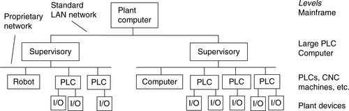
There is increasing use made of systems that can both control and monitor industrial processes. This involves control and the gathering of data. The term SCADA, which stands for supervisory control and data acquisition system, is widely used for such a system.
4.4.2. Network Standards
Interconnecting several devices can present problems of compatibility; for example, they may operate at different baud rates or use different protocols. To facilitate communications between devices, the International Standards Organization (ISO) in 1979 devised a model to be used for standardization for open systems interconnection (OSI); the model is termed the ISO OSI model. A communication link between items of digital equipment is defined in terms of physical, electrical, protocol, and user standards, the ISO OSI model breaking this down into seven layers (Figure 4.29).
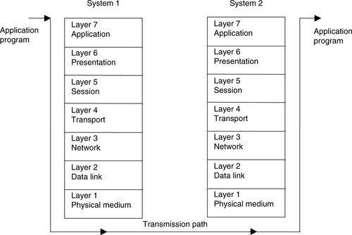
The function of each layer in the model is:
Layer 1: Physical medium. This layer is concerned with the coding and physical transmission of information. Its functions include synchronizing data transfer and transferring bits of data between systems.
Layer 2: Data link. This layer defines the protocols for sending and receiving information between systems that are directly connected to each other. Its functions include assembling bits from the physical layer into blocks and transferring them, controlling the sequence of data blocks, and detecting and correcting errors.
Layer 3: Network. This layer defines the switching that routes data between systems in the network.
Layer 4: Transport. This layer defines the protocols responsible for sending messages from one end of the network to the other. It controls message flow.
Layer 5: Session. This layer provides the function to set up communications between users at separate locations.
Layer 6: Presentation. This layer ensures that information is delivered in an understandable form.
Layer 7: Application. This layer has the function of linking the user program into the communication process and is concerned with the meaning of the transmitted information.
Each layer is self-contained and only deals with the interfaces of the layer immediately above and below it; it performs its tasks and transfers its results to the layer above or the layer below. It thus enables manufacturers of products to design products operable in a particular layer that will interface with the hardware of other manufacturers.
To illustrate the function of each layer, consider the analogy of making a telephone call. The physical medium is the telephone line, and layer 1 has to ensure that the voice signal is converted into an electrical signal for transmission and then, at the other end of the line, back into an electrical signal. Layer 1 thus defines the types of connectors and the signal levels required. Layer 2 ensures that words that are not clearly received are notified back to the sender for retransmission. Layer 3 provides the mechanism for dialing the number of the person to be called to make the connection between sender and receiver. Layer 4 is used to ensure that the messages are transmitted without loss. Layer 5 provides the protocols that can be used to set up a call between specific individuals—for example, for someone in an office to be brought to the telephone. Layer 6 resolves the problem of language so that both caller and receiver are speaking the same language. Layer 6 gives the procedures that are to be adopted for conveying particular pieces of information, such as the quantity to be ordered followed by the reference number of the product in a catalog.
In 1980, the Institute of Electronic and Electrical Engineers (IEEE) began Project 802. This is a model that adheres to the OSI Physical layer but that subdivided the Data link layer into two separate layers: the Media Access Control (MAC) layer and the Logical Link Control (LLC) layer. The MAC layer defines the access method to the transmission medium and consists of a number of standards to control access to the network and ensure that only one user is able to transmit at any one time. One standard is IEEE 802.3 Carrier Sense Multiple Access and Collision Detection (CSMA/CD); stations have to listen for other transmissions before being able to gain control of the network and transmit. Another standard is IEEE 802.4 Token Passing Bus; with this method a special bit pattern, the token, is circulated, and when a station wants to transmit, it waits until it receives the token and then attaches it to the end of the data. The LLC layer is responsible for the reliable transmission of data packets across the Physical layer.
4.5. Examples of Commercial Systems
The following are examples of systems that may be met with installations involving PLCs.
4.5.1. MAP
By 1990 General Motors in the United States had a problem automating its manufacturing activities; the company needed all its systems to be able to talk to each other. It thus developed a standard communications system for factory automation applications, called the manufacturing automation protocol (MAP). The system applied to all systems on the shop floor, such as robot systems, PLCs, and welding systems. Table 4.3 shows the MAP model and its relationship to the ISO model. In order for non-OSI equipment to operate on the MAP system, gateways may be used. These are self-contained units or interface boards that fit in the device so that messages from a non-OSI network/device may be transmitted through the MAP broadband token bus to other systems.
The application layer supports the Manufacturing Message Service (MMS), which defines the interactions between PLCs and numerically controlled machines and robots.
For the data link, methods are needed to ensure that only the user of the network is able to transmit at any one time, and for MAP the method used is token passing. The term broadband is used for a network in which information is modulated onto a radio frequency carrier that is then transmitted through the coaxial cable.
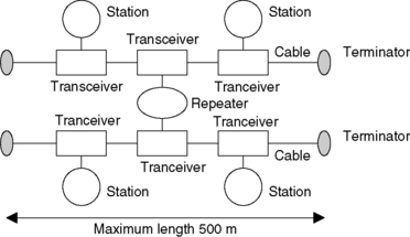
MAP is not widely used; a more commonly used system is the Ethernet. This is a single bus system with CSMA/CD used to control access. It uses coaxial cable with a maximum length of 500 m; up to 1024 stations can be accommodated, and repeaters that restore signal amplitude, waveform, and timing can be used to extend this capability (Figure 4.30). Each station is connected to the bus via a transceiver, which clamps onto the bus cable. The term vampire tap is used for the clamp on to the cable since stations can be connected or removed without disrupting system operation.
The term baseband is used when the signal is transmitted as just a series of voltage levels directly representing the bits being transmitted.
4.5.2. Ethernet
Ethernet does not have a master station, each connected station being of equal status, and so we have peer-to-peer communication. A station that wants to send a message on the bus will determine whether the bus is clear and, when it is, put its message frame on the bus. There is the slight probability that more than one station will sense an idle bus and attempt to transmit. Thus each sender monitors the bus during transmission and detects when the signal on the bus does not match its own output. When such a “collision” is detected, the transmission continues for a short while in order to give time to other stations to detect the collision and then attempts to retransmit at a later time. Each message includes a bit sequence to indicate the destination address, source address, the data to be transmitted, and a message check sequence. The message check sequence contains the cycle redundancy check (see Section 4.3.4). At each receiving station the frame's destination address is checked to determine whether the frame is destined for it. If so, it accepts the message. Ethernet is widely used where systems involve PLCs having to communicate with computers. The modular Allen-Bradley PLC-5 can be configured for use with a range of communication networks by the addition of suitable modules (refer back to Figure 1.15), a module enabling use with Ethernet. Ethernet is faster than MAP because the token-passing method of MAP is slower than the method used with Ethernet. PLC manufacturers often have their own networks, in addition to generally offering the possibility of Ethernet.
4.5.3. ControlNet
This is a network used by Allen-Bradley. Data is placed on the network with no indication as to who it is for. All the stations using this data can thus simultaneously accept it at the same time. This reduces the number of messages needed to be placed on the network and so increases the network speed. This allows PLC racks and their data to be shared equally among several processors and not be just dedicated to one. Network access is controlled by a timing algorithm called Concurrent Time Domain Multiple Access (CTDMA), which determines a node's ability to transmit in the network.
4.5.4. DeviceNet
This is based on the Controller Area Network (CAN), a system that has been widely used with cars (see Section 4.3.2). Each device in the network is requested to send or receive an update of its status, with generally each being requested to respond in turn. Devices are configured to automatically send messages at scheduled intervals, sending messages only when their status changes. DeviceNet is generally a subnetwork of a PLC that is connected to an Ethernet or ControlNet network and is used to link such devices as sensors, motor starters, and pneumatic valves.
4.5.5. Allen-Bradley Data Highway
The Allen-Bradley data highway is a peer-to-peer system developed for Allen-Bradley PLCs and uses token passing to control message transmission. The station addresses of each PLC are set by switches on each PLC. Communication is established by a single message on the data highway, specifying the sending and receiving addresses and the length of block to be transferred.
4.5.6. Profibus
Process Field Bus (Profibus) is a system that was developed in Germany and is used by Siemens with its PLCs. Profibus DP (Decentralized Periphery) is a device-level bus that usually operates with a single DP master and several slaves. Several such DP systems can be installed on one Profibus network. The transmissions are via RS485 (similar to RS422; see Section 4.3.2) or glass fiber optics. Such a system is comparable to DeviceNet. Profibus PA (Process Automation) is an extension of Profibus DP for data transmission from devices such as sensors and actuators. Profibus DP can be connected to Profibus PA using a DP/PA coupler if the work can be operated at 45.45 kbits/s; otherwise a DP/PA link has to be used to convert the data transfer rate of Profibus DP to that of Profibus PA.
4.5.7. Factory-Floor Network
A factory-floor network can use a number of network systems. Thus there may be Ethernet to provide the information layer for data collections and program maintenance, with the next layer down being ControlNet, to deal with real-time input/output processing, and, at the lowest layer, DeviceNet, to deal with sensors and drives. PLCs would take instructions from the Ethernet layer and exercise control through the ControlNet layer.
4.6. Processing Inputs
A PLC is continuously running through its program and updating it as a result of the input signals. Each such loop is termed a cycle. PLCs could be operated by each input being examined as it occurred in the program and its effect on the program determined and the output correspondingly changed. This mode of operation is termed continuous updating.
Because, with continuous updating, there is time spent interrogating each input in turn, the time taken to examine several hundred input/output points can become comparatively long. To allow more rapid execution of a program, a specific area of RAM is used as a buffer store between the control logic and the input/output unit. Each input/output has an address in this memory. At the start of each program cycle the CPU scans all the inputs and copies their status into the input/output addresses in RAM. As the program is executed, the stored input data is read, as required, from RAM and the logic operations are carried out. The resulting output signals are stored in the reserved input/output section of RAM. At the end of each program cycle all the outputs are transferred from RAM to the appropriate output channels. The outputs then retain their status until the next updating. This method of operation is termed mass I/O copying. The sequence can be summarized as follows (Figure 4.31):

1 Scan all the inputs and copy into RAM.
2 Fetch and decode and execute all program instructions in sequence, copying output instructions to RAM.
3 Update all outputs.
4 Repeat the sequence.
The time taken to complete a cycle of scanning inputs and updating outputs according to the program instructions, that is, the cycle time, though relatively quick, is not instantaneous and means that the inputs are not watched all the time, but samples of their states are taken periodically. A typical cycle time is on the order of 10 to 50 ms. This means that the inputs and outputs are updated every 10 to 50 ms and thus there can be a delay of this order in the system reaction. It also means that if a very brief input cycle appears at the wrong moment in the cycle, it could be missed. In general, any input must be present for longer than the cycle time. Special modules are available for use in such circumstances.
Consider a PLC with a cycle time of 40 ms. What is the maximum frequency of digital impulses that can be detected? The maximum frequency will be if one pulse occurs every 40 ms, that is, a frequency of 1/0.04 = 25 Hz.
The cycle or scanning time for a PLC, i.e. its response speed, is determined by:
1 The CPU used.
2 The size of the program to be scanned.
3 The number of input/outputs to be read.
4 The system functions that are in use; the greater the number, the slower the scanning time.
As an illustration, the Mitsubishi compact PLC, MELSEC FX3U (see Section 1.4), has a quoted program cycle time of 0.065 μs per logical instruction. Thus the more complex the program, the longer the cycle time will be.
4.7. I/O Addresses
The PLC has to be able to identify each particular input and output. It does this by allocating addresses to each input and output. With a small PLC this is likely to be just a number, prefixed by a letter to indicate whether it is an input or an output. Thus for the Mitsubishi PLC we might have inputs with addresses X400, X401, X402, and so on and outputs with addresses Y430, Y431, Y432, and so on, the X indicating an input and the Y an output. Toshiba uses a similar system.
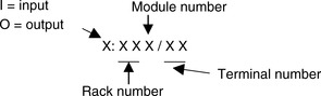
With larger PLCs that have several racks of input and output channels, the racks are numbered. With the Allen-Bradley PLC-5, the rack containing the processor is given the number 0 and the addresses of the other racks are numbered 1, 2, 3, and so on, according to how setup switches are set. Each rack can have a number of modules, and each one deals with a number of inputs and/or outputs. Thus addresses can be of the form shown in Figure 4.32. For example, we might have an input with address I:012/03. This would indicate an input, rack 01, module 2, and terminal 03.
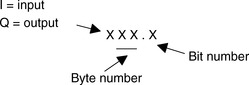
With the Siemens SIMATIC S5, the inputs and outputs are arranged in groups of eight. Each such group is termed a byte, and each input or output within a group of eight is termed a bit. The inputs and outputs thus have their addresses in terms of the byte and bit numbers, effectively giving a module number followed by a terminal number, a full stop (.) separating the two numbers. Figure 4.33 shows the system. Thus I0.1 is an input at bit 1 in byte 0, and Q2.0 is an output at bit 0 in byte 2.
The GEM-80 PLC assigns inputs and output addresses in terms of the module number and terminal number within that module. The letter A is used to designate inputs, and B outputs. Thus A3.02 is an input at terminal 02 in module 3, and B5.12 is an output at terminal 12 in module 5.
In addition to using addresses to identify inputs and outputs, PLCs also use their addressing systems to identify internal, software-created devices, such as relays, timers, and counters.
Summary
The input/output units of PLCs are designed so that a range of input signals can be changed into 5 V digital signals and a range of output signals are available. For a PLC input unit with sourcing, it is the source of the current supply for the input device connected to it; with sinking, the input device provides the current to the input unit. For a PLC output unit with sourcing, it provides the current to the output device, and for sinking, the output device produces the current for the PLC output. Output units can be relay, transistor, or triac.
For inputs, signal conditioning is generally used to convert analog signals to a current in the range 4 to 20 mA and, thus, by passing through a 250 Ω resistor to a 1 to 5 V input signal. This might be achieved by a potential divider or perhaps an operational amplifier. An operational amplifier can be used to compare two signals and give an on/off signal based on their relative values.
Serial communication is when data is transmitted one bit at a time. Parallel communication occurs when a data word is separated into its constituent bits and each bit is simultaneously transmitted along parallel cables. The most common serial standard is RS232; other standards are RS422 and RS423. The 20 mA loop can be used for serial communication. The most common parallel standard interface is IEEE-488. Protocols are necessary to exercise control of the flow of data between devices. The most commonly used code for the transmission of characters is ASCII.
The term local area network (LAN) describes a communications network designed to link computers and their peripherals within the same building or site. Networks can take three forms: start, bus, or ring. Often PLCs figure in a hierarchy of communications, at the lowest level inputs and output devices, at the next level small PLCs or computers, and at the next level, larger PLCs and computers. The ISO OSI model has been devised for standardization for open systems interconnection. Examples of commercial network systems are MAP, Ethernet, ControlNet, DeviceNet, Allen-Bradley Data Highway, and Profibus.
A PLC is continuously running through its program and updating it. It does this by mass I/O copying, in which all the inputs are scanned and copied into RAM, then fetched and decoded, and all program instructions are executed in sequence and output instructions copied to RAM. Then all the outputs are updated before repeating the sequence. The PLC has to be able to identify each particular input and output, and it does this by allocating addresses to each input and output.
Problems
Problems 1 through 15 have four answer options: A, B, C, or D. Choose the correct answer from the answer options.
1 An ADC is used to sample the output voltage from a pressure sensor. If the output from the sensor is 0 V when the pressure is 0 kPa and 10 V when it is 10 kPa, the minimum number of ADC bits needed to resolve the sensor output if the sensor error is not to exceed 0.01 kPa is:
A 4
B 8
C 10
D 12
2 A 12-bit ADC can be used to represent analog voltages over its input range with:
A 12 different binary numbers
B 24 different binary numbers
C 144 different binary numbers
D 4096 different binary numbers
3 For an analog input range of 0 to 10 V, the minimum size ADC needed to register a change of 0.1 V is:
A 4-bit
B 6-bit
C 8-bit
D 12-bit
4 An inverting operational amplifier circuit has an input resistance of 10 kΩ and feedback resistance of 100 kΩ. The closed-loop gain of the amplifier is:
A –100
B –10
C +10
D +100
Problems 5 and 6 refer to an operational amplifier with a closed loop gain of 100 and an input resistance of 47 kΩ.
5 The feedback resistor for an inverting op-amp amplifier will be:
A 4.65 kΩ
B 4.7 kΩ
C 465 kΩ
D 470 kΩ
6 The feedback resistor for a noninverting op-amp amplifier will be:
A 4.65 kΩ
B 4.7 kΩ
C 465 kΩ
D 470 kΩ
7 Decide whether each of these statements is true (T) or false (F). A serial communication interface:
(i) Involves data being transmitted and received one bit at a time.
(ii) Is a faster form of transmission than parallel communication.
A (i) T (ii) T
B (i) T (ii) F
C (i) F (ii) T
D (i) F (ii) F
8 Decide whether each of these statements is true (T) or false (F). The RS232 communications interface:
(i) Is a serial interface.
(ii) Is typically used for distances up to about 15 m.
A (i) T (ii) T
B (i) T (ii) F
C (i) F (ii) T
D (i) F (ii) F
Problems 9 and 10 refer to the following, which shows the bits on an RS232 data line being used to transmit the data 1100001:
0110000111
X YZ
9 Decide whether each of these statements is true (T) or false (F). The extra bits X and Z at the beginning and the end are:
(i) To check whether the message is corrupted during transmission.
(ii) To indicate where the data starts and stops.
A (i) T (ii) T
B (i) T (ii) F
C (i) F (ii) T
D (i) F (ii) F
10 Decide whether each of these statements is true (T) or false (F). Bit Y is:
(i) The parity bit showing odd parity.
(ii) The parity bit showing even parity.
A (i) T (ii) T
B (i) T (ii) F
C (i) F (ii) T
D (i) F (ii) F
11 Decide whether each of these statements is true (T) or false (F). The parallel data communication interface:
(i) Enables data to be transmitted over short distances at high speeds.
(ii) A common standard is IEEE-488.
A (i) T (ii) T
B (i) T (ii) F
C (i) F (ii) T
D (i) F (ii) F
12 Decide whether each of these statements is true (T) or false (F). For communications over distances of the order of 100 to 300 m with a high transmission rate:
(i) The RS232 interface can be used.
(ii) The 20 mA current loop can be used.
A (i) T (ii) T
B (i) T (ii) F
C (i) F (ii) T
D (i) F (ii) F
13 Decide whether each of these statements is true (T) or false (F). With input/output processing, mass input/output copying:
(i) Scans all the inputs and copies their states into RAM.
(ii) Is a faster process than continuous updating.
A (i) T (ii) T
B (i) T (ii) F
C (i) F (ii) T
D (i) F (ii) F
14 The cycle time of a PLC is the time it takes to:
A Read an input signal.
B Read all the input signals.
C Check all the input signals against the program.
D Read all the inputs, run the program, and update all outputs.
15 Decide whether each of these statements is true (T) or false (F). A PLC with a long cycle time is suitable for:
(i) Short duration inputs.
(ii) High-frequency inputs.
A (i) T (ii) T
B (i) T (ii) F
C (i) F (ii) T
D (i) F (ii) F
16 Specify (a) the odd parity bit and (b) the even parity bit to be used when the data 1010100 is transmitted.
17 Explain the purpose of using a parity bit.
18 Explain the continuous updating and the mass input/output copying methods of processing inputs/outputs.
19 What input resistance and feedback resistance can be used with an inverting operational amplifier circuit to give a gain of –100?
20 Compare the star, bus and ring forms of network and the methods used to avoid problems with messages.
21 What are the functions of (a) Profibus DP and Profibus PA, (b) ControlNet, and DeviceNet?
22 A network is said to involve token passing. What does this mean?
Finding-Out Tasks
23 Look up the network systems that the PLCs of a particular manufacturer are designed to operate with.
..................Content has been hidden....................
You can't read the all page of ebook, please click here login for view all page.