
15 I Slipped a Little, but Laphroaig was there
Aide-toi et le ciel t’aidera; эTO самиздат.
Compiled on June 17, 2017. Free Radare2 license included with each and every copy!
€0, $0 USD, $0 AUD, 10s 6d GBP, 0 RSD, 0 SEK, $50 CAD, 6 × 1029 Pengő (3 × 10⁸ Adópengő).
Neighbors, please join me in reading this sixteenth release of the International Journal of Proof of Concept or Get the Fuck Out, a friendly little collection of articles for ladies and gentlemen of distinguished ability and taste in the field of reverse engineering and the study of weird machines. This release is a gift to our fine neighbors in Montréal and Las Vegas.
After our paper release, and only when quality control has been passed, we will make an electronic release named pocorgtfo15.pdf. It is a valid PDF document and a ZIP file of the relevant source code. Those of you who have laser projection equipment supporting the ILDA standard will find that this issue can be handily projected by your laser beams.
At BSides Knoxville in 2015, Brandon Wilson gave one hell of a talk on how he dumped the cartridge of Pier Solar, a modern game for the Sega Genesis; the lost lecture was not recorded and the slides were never published. After others failed with traditional cartridge dumping techniques, Brandon jumped in to find that the cartridge only provides the first 32 kB until an unlock sequence is executed, and that it will revert to the first 32 KB if it ever detects that the CPU is not executing from ROM. On page 152, Brandon will explain his nifty tricks for avoiding these protection mechanisms, armed with only the right revision of Sega CD, a serial cable, and a few cheat codes for the Game Genie.
Pastor Laphroaig is back on page 174 with a sermon on alternators, Studebakers, and bug hunting in general. This allegory of a broken Ford might teach you a thing or two about debugging, and why all the book learning in the world won’t match the experience of repairing your own car.
Page 180 by Saumil Shah reminds us of those fine days when magazines would include type-in code. This particular example is one that Saumil authored twenty-five years ago, a stub that produces a self-printing COM file for DOS.

Don A. Bailey presents on page 182 an introduction to writing shellcode for the new RISC-V architecture, a modern RISC design which might not yet have the popularity of ARM but has much finer prospects than MIPS.
Our longest article for this issue, page 199 presents the monumental task of cracking Gumball for the Apple ][. Neighbors 4am and Peter Ferrie spent untold hours investigating every nook and cranny of this game, and their documentation might help you to preserve a protected Apple game of your own, or to craft some deviously clever 6502 code to stump the finest of reverse engineers.
Evan Sultanik has been playing around with the internals of Git, and on page 292 he presents a PDF which is also a Git repository containing its own source code.
Rob Graham is our most elusive author, having promised an article for PoC∥GTFO 0x04 that finally arrived this week. On page 308 he will teach you how to write Ethernet card drivers in userland that never switch back to the kernel when sending or receiving packets. This allows for incredible improvements to speed and drastically reduced memory requirements, allowing him to portscan all of /0 in a single sweep.
Ryan Speers and Travis Goodspeed have been toying around with MIPS anti-emulation techniques, which this journal last covered in PoC∥GTFO 6:6 by Craig Heffner. This new technique, found on page 332, involves abusing the real behavior of a branch-delay slot, which is a bit more complicated than what you might remember from your Hennessy and Patterson textbook.
Page 344 describes how BSDaemon and NadavCH reproduced the results of the Gynvael Coldwind’s and Jur00’s Pwnie-winning 2013 paper on race conditions, using Intel’s SAE tracer to not just verify the results, but also to provide new insights into how they might be applied to other problems.
Chris Domas, who the clever among you remember from his Movfuscator, returns on page 354 to demonstrate that X86 is Turing-complete without data fetches.
Tobias Ospelt shares with us a nifty little tale on page 359 about the Java Key Store (JKS) file format, which is the default key storage method for both Java and Android. Not content with a simple proof of concept, Tobias includes a fully functional patch against Hashcat to properly crack these files in a jiffy.
There’s a trick that you might have fallen prey to: sometimes there’s a perfectly innocent thumbnail of an image, but when you click on it to view the full image, you are hit with different graphics entirely. On page 375, Hector Martin presents one technique for generating these false thumbnail images with gAMA chunks of a PNG file.

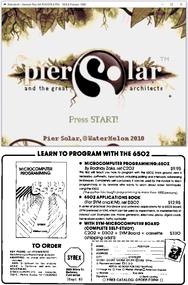
15:02 Pier Solar and the Great Reverser
by Brandon L. Wilson
Hello everyone!
I’m here to talk about dumping the ROM from one of the most secure Sega Genesis game ever created.
This is a story about the unusual, or even crazy techniques used in reverse engineering a strange target. It demonstrates that if you want to do something, you don’t have to be the best or the most qualified person to do it—you should do what you know how to do, whatever that is, and keep at it until it works, and eventually it will pay off.
First, a little background on the environment we’re talking about here. For those who don’t know, the Sega Genesis is a cartridge-based, 16-bit game console made by Sega and released in the US in 1989. In Europe and Japan, it was known as the Sega Mega Drive.
As you may or may not know, there were three different versions of the Genesis. The Model 1 Genesis is on the left of Figure 15.11. Some versions of this model have an extension port, which is actually just a third controller port. It was originally intended for a modem add-on, which was later scrapped.

Figure 15.11: Sega Genesis models 1, 2, and 3.
Some versions of the Model 1, and all of the Model 2 devices, include a cartridge protection mechanism called the TMSS, or TradeMark Security System. Basically this was just some extra logic to lock up some of the internal Genesis hardware if the word “SEGA” didn’t appear at 0x100 in the ROM and if the ASCII bytes representing “S”, “E”, “G”, “A” weren’t written to a hardware register at 0xA14000. Theoretically only people with official Sega documentation would know to put this code in their games, thereby preventing unlicensed games, but that of course didn’t last long•

And then there’s the Model 3 of my childhood living room, which generally sucked. It doesn’t support the Sega CD, Game Genie, or any other interesting accessories.
There was also a not-as-well-known CD add-on for the Genesis called the Sega CD, or the Mega CD in Europe and Japan, released in 1992. It allowed for slightly-nicer-looking CD-based games as an attempt to extend the Genesis’ life, but like many other attempts to do so, that didn’t really work out.
Sega CD has its own Motorola 68k processor and a second BIOS, which gets executed if you don’t have a cartridge in the main slot on top. That way you can still play all your old Genesis games, but if you didn’t have one of those games inserted, it would boot off the Sega CD BIOS and then whatever CD you inserted.

There were two versions of the Sega CD. The was shaped to fit the Model 1 Genesis, and while the second was modeled for the shape of the Model 2, it would fit either model.
————
So finally we get to the game itself, a game called Pier Solar. It was released in 2010 and is a “homebrew” game, which means it was programmed by a bunch of fans of the Genesis, not in any way licensed by Sega. Rather than just playing it in an emulator, they took the time to produce an actual cartridge with a fancy case, a printed manual, and all the other trimmings of a real game.
It’s unique in that it is the only game ever to use the Sega CD add-on for an enhanced soundtrack while you’re playing the game, and it has what they refer to as a “high-density” cartridge, which means it has an 8MB ROM, larger than any other Genesis game ever made.
It’s also unique in that its ROM had never been successfully dumped by anyone, preventing folks from playing it on an emulator. The lack of a ROM dump was not from lack of trying, of course.
Taking apart the cartridge, you can see that they’re very, very protective of something. They put some sort of black epoxy over the most interesting parts of the board, to prevent analysis or direct dumping of what is almost certainly flash memory.
Since they want to protect this, it’s our obligation to try and understand what it is and, if necessary, defeat it. I can’t help it; I see something that someone put a lot of effort into protecting, and I just have to un-do it.

I have no idea how to get that crud off, and I have to assume that since they put it on there, it’s not easy to remove. We have to keep in mind, this game and protection were created by people with a long history of disassembling Genesis ROMs, writing Genesis emulators, and bypassing older forms of copy protection that were used on clones and pirate cartridges. They know what people are likely to try in order to dump it and what would keep it secure for a long time.
So we’re going to have to get creative to dump this ROM.
There are two methods of dumping Sega Genesis ROMs. The first would be to use a device dedicated to that purpose, such as the Retrode. Essentially it pretends to be a Sega Genesis and retrieves each byte of the ROM in order until it has them all.
Unfortunately, when other people applied this to the 8MB Pier Solar, they reported that it just produces the same 32KB over and over again. That’s obviously too small, so they must have some hardware under that black crud that ensures it’s actually running in a Sega Genesis.
So, we turn to the other main method of dumping Genesis ROMs, which involves running a program on the Genesis itself to read the inserted cartridge’s data and output it through one of the controller ports, which as I mentioned before is actually just a serial port. The people with the ability to do this also reported the same 32KB mirrored over and over again, so that doesn’t work either.
Where’s the rest of the ROM data? Well, let’s take a step back and think about how this works. When we do a little Googling, we find that “large” ROMs are not a new thing on the Genesis. Plenty of games would resort to tricks to access more data than the Genesis could normally.
The system only maps four megabytes of cartridge memory, probably because Sega figured, “Four megs is enough ROM for anybody!” So it’s impossible for it to directly reference memory beyond this region. However some games, such as Super Street Fighter 2, are larger than that. That game in particular is five megabytes.
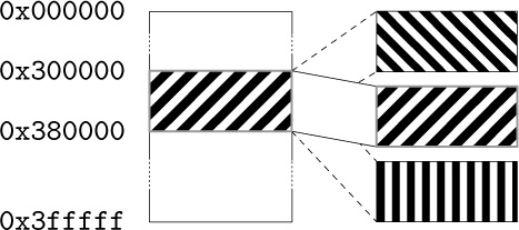
They get access to the rest of the ROM by using a really old trick called bank switching. Since they know they can only address 4MB, they just change which 4MB is visible at any one time, using external hardware in the cartridge. That external hardware is called a memory mapper, because it “maps” various sections of the ROM into the addressable area. It’s a poor man’s MMU.
So the game itself can communicate with the cartridge and tell the mapper “Hey, I need access to part of that last megabyte. Put it at address 0x300000 for me.” When you access the data at 0x300000, you’re really accessing the data at, say, 0x400000, which would normally be just outside of the addressable range. All this is documented online, of course. I found it by Googling about Genesis homebrew and programming your own games.

So where does this memory mapper live? It’s in the game cartridge itself. Since the game runs from the Genesis CPU, it needs a way to communicate with the cartridge to tell it what memory to map and where.
All Genesis I/O is memory-mapped, meaning that when you read from or write to a specific memory address, something happens externally. When you write to addresses 0xA130F3 through 0xA130FF, the cartridge hardware can detect that and take some kind of action. So for Super Street Fighter 2, those addresses are tied to the memory mapper hardware, which swaps in blocks of memory as needed by the game.
Pier Solar does the same thing, right? Not exactly; loading up the first 32KB in IDA Pro reveals no reads or writes here, nor to anywhere else in the 0xA130xx range for that matter. So now what?
Well, and this is something important that we have to keep in mind, if the game’s code can access all the ROM data, then so can our code. Right? If they can do it, we can do it.
————
So the question becomes, how do we run code on a Sega Genesis? The same way others tried dumping the ROM—through what’s called the Sega CD transfer cable. This is an easy-to-make cable linking a PC’s parallel port with one of the Genesis’ controller ports, which as I said before is just a serial port. There are no resistors, capacitors, or anything like that. It’s literally just the parallel port connector, a cut-up controller cable, and the wire between them. The cable pinout and related software are publicly available online.0
As I mentioned before, while the Sega CD is attached, the Genesis boots from the top cartridge slot only if a game is inserted. Otherwise, it uses the BIOS to boot from the CD.
Since they weren’t too concerned with CD piracy way back in 1992, there is no protection at all against simply burning a CD and booting it. We burn a CD with a publicly-available ISO of a Sega CD program that waits to receive a payload of code to execute from a PC via the transfer cable. That gives us a way of writing code on a PC, transferring it to a Sega Genesis + Sega CD, running it, and communicating back and forth with a PC. We now have ourselves a framework for dumping the ROM.
Great, we found some documentation online about how to send code to a Genesis and execute it, now what? Well, let’s start with trying to understand what code for this thing would even look like. Wikipedia tells us that it has two processors. The main processor is a Motorola 68000 CPU running at 7.6MHz, and it can directly access the other CPU’s RAM.
The second CPU is a Zilog Z80 running at 4MHz, whose sole purpose is to drive the Yamaha YM2612 FM sound chip. The Z80 has its own RAM, which can be reset or controlled by the main Motorola 68000. It also has the ability to access cartridge ROM—so typically a game would play sound by transferring over to the Z80’s RAM a small program that reads sound data from the cartridge and dumps it to the Yamaha sound chip. So when the game wanted to play a sound, the Motorola 68k would reset the Z80 CPU, which would start executing the Z80 program and playing the sound.

So anyway, combined that’s 72KB of RAM: 64KB for the 68k and 8KB for the Z80.
Documentation also tells us the memory map of the Genesis. The first part we’ve already covered, that we can access up to 0x400000, or 4MB, of the cartridge memory. The next useful area starts at 0xA00000, which is where you would read from or write to the Z80’s RAM.
After that is the most important area, starting at 0xA10000, which is where all the Genesis hardware is controlled. Here we find the registers for manipulating the two controller ports, and the area I mentioned earlier about communicating directly with the hardware in the cartridge.

We also have 64KB of Motorola 68k RAM, starting at address 0xFF0000. This should give you an idea of what code would look like, essentially reading from and writing to a series of memory mapped I/O registers.
Reports online are that the standard Sega CD transfer cable ROM dumping method doesn’t work, but since we have the source code to it, let’s go ahead and try it ourselves. To do that, I needed an older Genesis and Sega CD. I went to a flea market and picked up a Model 1 Sega Genesis and Model 2 Sega CD for a few dollars, then soldered together a transfer cable.
We now have the Sega Genesis attached to the Sega CD and our boot CD inserted, we then cover up the “cartridge detect” pin with tape, so that it won’t detect an inserted cartridge. It will boot to the Sega CD.
As the system turns on, the Sega CD and then our burned boot CD starts up. Then the ROM dumping program is transferred over from the PC and executed on the Genesis.
The dump is transferred back to the PC via the transfer cable. We take a look at it in a hex editor, but the infernal thing is still mirrored.
Why is this happening? Well, we’re reading the data off the cartridge using the Genesis CPU, the same way the game runs, so maybe the cartridge hardware requires a certain series of instructions to execute first? I mean, a certain set of values might need to be written to a certain address, or a certain address might need to be read.
If that’s the case, maybe we should let the game boot as much as possible before we try the dump. But, if the game has booted, we’re going to need to steal control away from it, which means we need to change how it runs.
Enter the Game Genie, which you might remember from when you were a kid. You’d plug your game into the cartridge slot on top of the Game Genie, then put that in your Genesis, turn it on, flip through a code book and enter your cheat codes, then hit START and cheat to your heart’s content.
As it turns out, this thing is actually very useful. What it really does is patch the game by intercepting attempts to read cartridge ROM, changing them before they make it to the console for execution. The codes are address/value pairs! For example, if there’s a check in a game to jump to a “you’re dead” subroutine when your health is at zero, you could simply NOP out that Motorola 68k assembly instruction. It will never take that jump, and your character will never die.
Those of you who grow up with this thing might remember that some games had a “master” code that was required before any other codes. That code was for defeating the ROM checksum check that the game does to make sure it hasn’t been tampered with. So once you entered the master code, you could make all the changes you wanted.
Since the code format is documented,1 we can easily make a Game Genie code that will change the value at a certain address to whatever we specify. We can make minor changes to the game’s code while it runs.
Due to the way the Motorola 68k works, we can only change one 16-bit word at a time, never just a single byte. No big deal, but keep it in mind because it limits the changes that we can make.
Well, that’s nice in theory, but can it really work with this game? First we fire up the game with the Game Genie plugged in, but don’t enter any codes, just to see if the cartridge works while it’s attached.
Yes, it does, so next we fire up the game, again with the Game Genie plugged in, but this time we enter a code that, say, locks up hard. Now, that’s not the best test in the world, since the code could be doing something we don’t understand, but if the game suddenly won’t boot, we know at least we’ve made an impact.
Now, according to online documentation, the format of a Genesis ROM begins with a 256-byte interrupt vector table of the Motorola 68k, followed by a 256-byte area holding all sorts of information about the ROM, such as the name of the game, the author, the ROM checksum, etc. Then finally the game’s machine code begins at address 0x0200.
If we make a couple of Game Genie codes that place the Motorola 68k instruction “jmp 0x0200” at 0x200, the game will begin with an infinite loop. I tried it, and that’s exactly what happened. We can lock the game up, and that’s a pretty strong indication that this technique might work.
Getting back to our theory: if the game needs to execute a special set of instructions to make the 32KB mirroring stop, we need to let it run and then take back control and dump the ROM. How do we know when and where to do that? We fire up a disassembler and take a look.
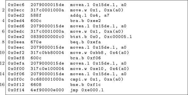
It is at 0x000F14 that the code takes its first jump outside of the first 32KB, to address 0x00E000. So assuming this code executes properly, we know that at the moment the game takes that jump, the mirroring is no longer occurring. That’s the safest moment to take control. We don’t yet have any idea what happens once it jumps there, as this first 32KB is all we have to study and work with.
So we can make 16-bit changes to the game’s code as it runs via the Game Genie, and separately, we can run code on the Genesis and access at least part of the cartridge’s ROM via the Sega CD. What we really need is a way to combine the two techniques.
So then I had an idea: What if we booted the Sega CD and wrote some 68k code to embed a ROM dumper at the end of 68k RAM, then insert the Game Genie and game while the system is on, then hit the RESET button on the console, which just resets the main 68k CPU, which means our ROM dumper at the end of 68k RAM is still there It should then go to boot the Game Genie this time instead of the Sega CD, since there’s now a cartridge in the slot, then enter Game Genie codes to make the game jump straight into 68k RAM, then boot the game, giving us control?
That’s quite a mouthful, so let’s go over it one more time.
- We write some 68k shellcode to read the ROM data and push it out the controller port back to the PC.
- To run this code, we boot the Sega CD, which receives and executes a payload from the PC.
- This payload copies our ROM dumping code to the end of 68k RAM, which the 32KB dump doesn’t seem to use.
- We insert our Game Genie and game into the Genesis. This makes the system lock up, but that’s not necessarily a bad thing, as we’re about to reset anyway.
- We hit the RESET button on the console. The Genesis starts to boot, detects the Game Genie and game cartridge so it boots from those instead of the CD.
- We enter our Game Genie codes for the game to jump into 68k RAM and hit START to start the game, aaaand …
- Attempting this technique, the system locks up just as we should be jumping into the payload left in RAM. But why?
I went over this over and over and over in my head, trying to figure out what’s wrong. Can you see what’s wrong with this logic?
Yeah, so, I failed to take into account anything the Game Genie might be doing to mess with our embedded ROM dumping code in the 68K’s RAM. When you disassemble the Game Genie’s ROM, you find that one of the first things it does is wipe out all of the 68K’s RAM.

We can’t leave code in main CPU RAM across a reboot because of the very same Game Genie that lets us patch the ROM to jump into our shellcode. So what do we do?
We know we can’t rely on our code still being in 68k RAM by the time the game boots, but we need something, anything to persist after we reset the console. Well, what about Z80’s RAM?
Studying the Game Genie ROM reveals that it puts a small Z80 sound program in Z80 RAM, for playing the code entry sound effects. This program is rather small, and the Game Genie doesn’t wipe out all of Z80 RAM first. It just copies in this little program, leaving the rest of Z80 memory alone.
So instead of putting our code at the end of 68K RAM, we can instead put it at the end of Z80 RAM, along with a little Z80 code to copy it back into 68k RAM. We can make a sequence of Game Genie codes that patches Pier Solar’s Z80 program to jump right to the end of Z80 RAM, where our Z80 code will be waiting. We’ll then be free to copy our 68k code back into 68k RAM, hopefully before the Game Genie makes the 68k jump there.
With this new arrangement, we get control of the 68K CPU after the game has booted! But the extracted data is still mirrored, even though we are executing the same way the real game runs.
Okay, so what are the differences between the game’s code and our code?
We’re using a Game Genie, maybe the game detects that? This is unlikely, as the game boots fine with it attached. If it had a problem with the Game Genie, you’d think it wouldn’t work at all.
Well, we’re running from RAM, and the game is running from ROM. Perhaps the cartridge can distinguish between instruction fetches of code running from ROM and the data fetches that occur when code is running from RAM?
Our only ability to change the code in ROM comes from the Game Genie, which is limited to five codes. A dumper just needs to write bytes in order to 0xA1000F, the Controller 2 UART Transmit Buffer, but code to do that won’t fit in five codes.

Luckily there is a cheat device called the Pro Action Replay 2 which supports 99 codes. These are extremely rare and were never sold in the States, but I was able to buy one through eBay. Unfortunately, the game doesn’t boot with it at all, even with no codes. It just sits at a black screen, even though the Action Replay works fine with other cartridges.
So now what? Well, we think that the CPU must be actively running from ROM, but except for minor patches with the Game Genie, we know our code can only run from RAM. Is there any way we can do both? Well, as it turns out, we already have the answer.
We have two processors, and we were already using both of them! We can use the Game Genie to make the 68k spin its wheels in an infinite loop in ROM, just like the very first thing we tried with it, while we use the other processor to dump it.
We were overthinking the first (and second) attempts to get control away from the game, as there’s no reason the 68K has to be the one doing the dumping. In fact, having the Z80 do it might be the only way to make this work.
So the Z80 dumper does its thing, dumping cartridge data through the Sega CD’s transfer cable while the 68K stays locked in an infinite loop, still fetching instructions from cartridge hardware! As far as the cartridge is concerned, the game is running normally.
And YES, finally, it works! We study the first 4MB in IDA Pro to see how the bank switching works. As luck would have it, Pier Solar’s bank switching is almost exactly the same as Super Street Fighter 2.
Armed with that knowledge, we can modify the dumper to extract the remaining 4MB via bank switching, which I dumped out in sixteen pieces very slowly, through lots and lots and lots of triggering this crazy boot procedure. I mean, I can’t tell you how excited I was that this crazy mess actually worked. It was like four o’clock in the morning, and I felt like I was on top of the world. That’s why I do this stuff; really, that payoff is so worth it. It’s just indescribable.
Now that I had a complete dump, I looked for the ROM checksum calculation code and implemented it PC-side, and it actually matched the checksum in the ROM header. Then I knew it was dumped correctly.
Now begins the long process of studying the disassembly to understand all the extra hardware. For example, the save-state hardware is just a serial EEPROM accessed by reads and writes to a couple of registers.
So now that we have all of it, what exactly can we say was the protection? Well, I couldn’t tell you how it works at a hardware level other than that it appears to be an FPGA, but, disassembly reveals these secrets from the software side.
The first 32KB is mirrored over and over until specific accesses to 0x18010 occur. The mirroring is automatically re-enabled by hardware if the system isn’t executing from ROM for more than some unknown amount of time.

The serial EEPROM, while it doesn’t require a battery to hold its data, does prevent the game from running in emulators that don’t explicitly support it. It also breaks compatibility with those flash cartridges that people use for playing downloaded ROMs on real consoles.
Once I got the ROM dumped, I couldn’t help but try to get it working in some kind of emulator, and at the time DGen was the easiest to understand and modify, so I did the bare minimum to get that working. It boots and works for the most part, but it has a few graphical glitches here and there, probably related to VDP internals I don’t and will never understand.2 Eventually somebody else came along and did it better, with a port to MESS.
Don’t think anything is beyond your abilities: use the skills you have, whatever they may be. Me, I do TI graphing calculator programming and reverse engineering as a hobby. The two main processors those calculators use are the Motorola 68K and Zilog Z80, so this project was tailor-made for me. But as far as the hardware behind it, I had no clue; I just had to make some guesses and hope for the best.
“This isn’t the most efficient method” and “Nobody else would try this method.” are not reasons to not work on something. If anything, they’re actually reasons to do it, because that means nobody else bothered to try it, and you’re more likely to be first. Crazy methods work, and I hope this little endeavor has proven that.
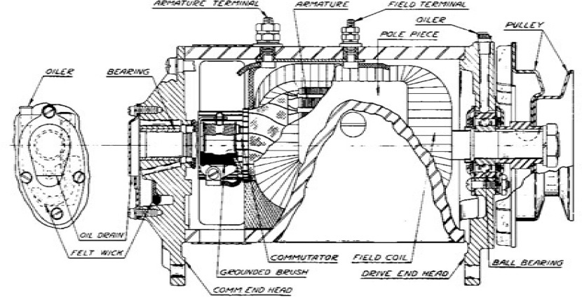
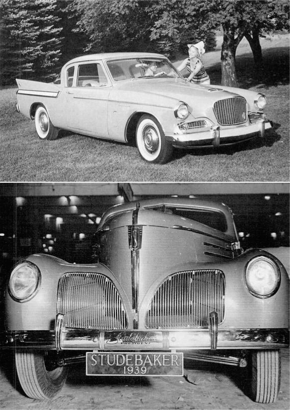
15:03 A Sermon on Alternators, Voltmeters, and Debugging
by Pastor Manul Laphroaig, who is not certified by ASE.
I have a story to tell, and it’s not a very flattering one.
A few years back, when I was having a bad day, I bought a five hundred dollar Mercedes and took to the open road. It had some issues, of course, so a hundred miles down the road, I stopped in rural Virginia and bought a new stereo. This was how I learned that installing a stereo in a Walmart parking lot looks a lot like stealing a stereo from a Walmart parking lot.0
I also learned rather quickly that my four courses of auto-shop in high school amounted to a lot of book knowledge and not that much practical knowledge. My buddies who bought old cars and fixed them first-hand learned—and still know—a hell of a lot more about their machines that I ever will about mine. When squirrels chewed through the wiring harness, when metal flakes made the windshield wiper activate on its own, when the fuel line was cut by rubbish in the street as I was tearing down the Interstate at Autobahn speeds, I often took the lazy way out and paid for a professional to repair it.
But while it’s true that you learn more by building your own birdfeeder, that’s not the purpose of this sermon. Today I’d like to tell you about some alternator trouble. Somehow, someway, by some mechanism unknown to gods and men, this car seemed to be killing every perfectly good alternator that was placed inside of it, and no mechanic could figure out why.
It went like this: I’d be off having adventures, then drop into town to pick up my wheels. Having been away for so long, the battery would be dead. “No big deal,” I’d say and jump-start the engine. After the engine caught, I’d remove the cables, and soon enough the battery would be dead again, the engine with it. So I’d switch to driving my Ford and send my car to the shop.1
The mechanics at the shop would test the alternator, and it’d look good. They’d test the battery, and it’d look good. Then they’d start the car, and the alternator’s voltage would be low, so they’d replace it out of caution. No one knew the root cause, but the part’s under warranty, and the labor is cheap, so who cares?
What actually happened is this: The alternator doesn’t engage until the engine revs beyond natural idling or starting. The designers must have done this to reduce the load on the starter motor, but it has the annoying side effect of letting the battery run to nothing after a jump start. The only indication to the driver is that the lights are a little dim until the gas is first pressed.
I learned this by accident after installing a voltmeter. Setting aside for the moment how absurd it is that a car ships without one, let’s consider how the mechanics were fooled. In software terms, we’d say that they were confronted with a poorly reproducible test case; they were bug-hunting from anecdotes, from hand-picked artisanal data. This always ends in disaster, whether it’s a frustrated software maintainer or a mechanic who becomes an unknowing accomplice to four counts of warranty fraud.
So what mistakes did I make? First, I outsourced my understanding to a shop rather than fixing my own birdfeeder. The mechanic at the shop would see my car once every six months, and he’d forget the little things. He never noticed that the lights were slightly dimmer before revving the engine, because he never started the car at night. To really understand something, you ought to have a deep familiarity with it; a passing view is bound to give you a quick little fix, or an exploit that doesn’t always achieve continuation on its target.
Further, he never noticed that the battery only died after a jumpstart, but never in normal use, because all of the cars that he sees have already exhibited one problem or another and most of them were daily drivers. Whenever you are hunting a rare bug, consider the pre-existing conditions that brought that crash to your attention.2
Getting back to the bastard who designed a car with a single idiot light and no voltmeter, the single handiest tool to avoid these unnecessary repairs would have been to reproduce the problem when the car wasn’t failing. Rather than spending months between the car failing to start, a voltmeter would have shown me that the voltage was low only before the engine was first revved up! In the same way, we should use every debugging tool at our disposal to make a problem reproducible in the shortest time possible, even if that visibility doesn’t end in the problem that was first reported.
Paying attention to the voltage during a few drives would have revealed the real problem, even when the battery is sufficiently charged that the engine doesn’t die. For this reason, we should be looking for the root cause of EVERYTHING, never settling for the visible effects.
We who play with computers have debugging tools that the best mechanics can only dream of. We have checkpoint-restart debuggers which can take a snapshot just before a failure, then repeatedly execute a crash until the cause is known. We have strace and dtrace and ftrace, we have disassemblers and decompilers, we have tcpdump and tcpreplay, we have more hooks than Muad’Dib’s Fedaykin!
We can deluge the machine with a thousand core dumps, then merge them into a single test case that reproduces a crash with crystal clarity; or, if we prefer, a proof of concept that escapes from the deepest sandbox to the outer limits! Yet the humble alternator still has important lessons to teach us.

15:04 Text2Com Silver Jubilee Edition
specially re-mastered for PoC∥GTFO by Saumil Shah with kind assistance from Mr. Udayan Shah
Text2COM generates self-displaying README.COM files by prefixing a short sequence of DOS Assembly instructions before a text file. The resultant file is an MS-DOS .COM program which can be executed directly from the command prompt.
The Text2COM code displays the contents of the appended file page by page. The executable code is created by is created by MS-DOS’s DEBUG program.
Then take any text file and concatenate it with README.BIN and store the resultant file as README.COM. You now have a self-displaying README.COM file!
C:>copy README.BIN+TEXT2COM.TXT README.COM


15:05 RISC-V Shellcode
by Don A. Bailey
RISC-V is a new and exciting open source architecture developed by the RISC-V Foundation. The Foundation has released the Instruction Set Architecture open to the public, and a Privilege Architecture Model that defines how general purpose operating systems can be implemented. Even more exciting than a modern open source processing architecture is the fact that implementations of the RISC-V are available that are fully open source, such as the Berkeley Rocket Chip0 and the PULPino.1
To facilitate silicon development, a new language developed at Berkeley, Chisel,2 was developed. Chisel is an open-source hardware language built from Scala, and synthesizes Verilog. This allows fast, efficient, effective development of hardware solutions in far less time. Much of the Rocket Chip implementation was written in Chisel.
Furthermore, and perhaps most exciting of all, the RISC-V architecture is 128-bit processor ready. Its ISA already defines methodologies for implementing a 128-bit core. While there are some aspects of the design that still require definition, enough of the 128-bit architecture has been specified that Fabrice Bellard has successfully implemented a demo emulator.3 The code he has written as a demo of the emulator is, perhaps, the first 128-bit code ever executed.
Binary Exploitation
To compromise a RISC-V application or kernel in the traditional memory corruption manner, one must understand both the ISA and the calling convention for the architecture. In RISC-V, the term XLEN is used to denote the native integer size of the base architecture, e.g. XLEN=32 in RV32G. Each register in the processor is of XLEN length, meaning that when a register is defined in the specification, its format will persist throughout any definition of the RISC-V architecture, except for the length, which will always equate to the native integer length.
General Registers
In general, RISC-V has 32 general (or x) registers: x0 through x31.4 These registers are all of length XLEN, where bit zero is the least-significant-bit and the most-significant-bit is XLEN-1. These registers have no specific meaning without the definition of the Application Binary Interface (ABI).
The ABI defines the following naming conventions to contextualize the general registers, shown in Figure 15.12.5
Floating-Point Registers
RISC-V also has 32 floating point registers fp0 through fp31, shown in Figure 15.13. The bit size of these registers is not XLEN, but FLEN. FLEN refers to the native floating point size, which is defined by which floating point extensions are supported by the implementation. If the ‘F’ extension is supported, only 32-bit floating point is implemented, making FLEN=32.6 If the ‘D’ extension is supported, 64-bit floating point numbers are supported, making FLEN=64.7 If the ‘Q’ extension is supported, quad-word floating point numbers are supported, and FLEN extends to 128.8
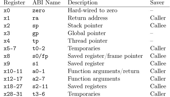
Figure 15.12: Naming conventions for general registers according to the current ABI.
Calling Convention
Like any Instruction Set Architecture (ISA), RISC-V has a standard calling convention. But, because of the RISC-V’s definition across multiple architectural subclasses, there are actually three standardized calling conventions: RVG, Soft Floating Point, and RV32E.
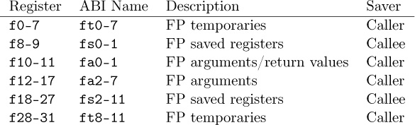
Figure 15.13: Floating point register naming convention according to the current ABI.
Naming ConventionsRISC-V’s architecture is somewhat reminiscent of the Plan 9 architecture naming style, where each architecture is assigned a specific alphanumeric A through Z or 0 through 9. RISC-V supports 24 architectural extensions, one for each letter of the English alphabet. The two exceptions are G and X. The G extension is actually a mnemonic that represents the RISC-V architecture extension set IMAFD, where I represents the base integer instruction set, M represents multiply/divide, A represents atomic instructions, F represents single-precision floating point, and D represents double-precision floating point. Thus, when one refers to RVG, they are indicating the RISC-V (RV) set of architecture extensions G, actually referring to the combination IMAFD.9
This colloquialism also implies that there is no specific architectural bit-space being singled out: all three of the 32-bit, 64-bit, and 128-bit architectures are being referenced. This is common in description of the architectural standard, software relevant to all architectures (a kernel port), or discussion about the ISA. It is more common, in development, to see the architecture described with the bit-space included in the name, e.g. RV32G, RV64G, or RV128G.
It is also worth noting that it is defined in the specification and core register set that an implementation of RISC-V can support all three bit-spaces in a single processor, and that the state of the processor can be switched at run-time by setting the appropriate bit in the Machine ISA Register (MISA).10
Thus, in this context, the RVG calling convention denotes the model for linking one function to another function in any of the three RISC-V bit-spaces.
RVGRISC-V is little-endian by definition and big or bi-endian systems are considered non-standard.11 Thus, it should be presumed that all RISC-V implementations are little-endian unless specifically stated otherwise.
To call any given function there are two instructions: Jump and Link and Jump and Link Register. These instructions take a target address and branch to it unconditionally, saving the return address in a specific register. To call a function whose address is within 1MB of the caller’s address, the jal instruction can be used:
To call a function whose address is either generated dynamically, or is outside of the 1MB target range, the jalr instruction must be used:

In both of the above examples, bits 7 through 11 of the encoded opcode equate to 0b00001. These bits indicate the destination register where the return address is stored. In this case, 1 is equivalent to register x1, also known as the return address register: ra. In this fashion, the callee can simply perform their specific functionality and return by using the contents of the register ra.
Returning from a function is even simpler. In the RISC-V ABI, we learned earlier that the return address is presumed to be stored in ra, or, general register x1. To return control to the address stored in ra, we simply use the Jump and Link Register instruction, with one slight caveat. When returning from a function, the return address can be discarded. So, the encoded destination register for jalr is x0. We learned earlier that x0 is hardwired to the value zero. This means that despite the return address being written to x0, the register will always read as the value zero, effectively discarding the return address.
Thus, a return instruction is colloquially:
204002a8: 00008067 ret
Which actually equates to the instruction:
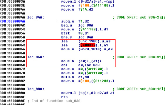
Local stack space can be allocated in a similar fashion to any modern processing environment. RISC-V’s stack grows downward from higher addresses, as is common convention. Thus, to allocate space for automatics, a function simply decrements the stack pointer by whatever stack size is required.


In the above example, a standard addi instruction (highlighted in red) is used to both create and destroy a stack frame of 32 bytes. Four of these bytes are used to store the value of ra. This implies that this function, arch_main, will make calls to other functions and will require the use of ra. The lines highlighted in green depict the saving and retrieval of the return address value.
This fairly standard calling convention implies that binary exploitation can be achieved, but has several caveats. Like most architectures, the return address can be overwritten in stack memory, meaning that standard stack buffer overflows can result in the control of execution. However, the return address is only stored in the stack for functions that make calls to other functions.
Leaf functions, functions that make no calls to other functions, do not store their return address on the stack. These functions, similar to other RISC architectures, must be attacked (1) by overwriting the previous function’s stack frame or stored return address, (2) by overwriting the return address value in register ra, or (3) by manipulating application flow by attacking a function-specific feature such as a function pointer
Soft-Float Calling ConventionWith regard to the threat of exploitation, the RISC-V soft-float calling convention has little effect on an attacker strategy. The jal/jalr and stack conventions from RVG persist. The only difference is that the floating point arguments are passed in argument registers according to their size. But, this typically has little effect on general exploitation theory and will only be abused in the event that there is an application-specific issue.
It is notable, however, that implementations with hard-float extensions may be vulnerable to memory corruption attacks. While hard-float implementations use the same RVG calling conventions as defined above, they use floating point registers that are used to save and restore state within the floating point ecosystem. This may provide an attacker an opportunity to affect an application in an unexpected manner if they are able to manipulate saved registers (either in the register file or on the stack).
While this is application specific and does not apply to general exploitation theory, it is interesting in that the RISC-V ABI does implement saved and temporary registers specifically for floating point functionality.
RV32E Calling ConventionIt’s important to note the RV32E calling convention, which is slightly different from RVG. The E extension in RISC-V denotes changes in the architecture that are beneficial for 32-bit Embedded systems. One could liken this model to ARM’s Cortex-M as a variant of the Cortex-A/R, except that RVG and RV32E are more tightly bound.
RV32E only uses 16 general registers rather than 32, and never has a hard-floating point extension. As a result, exploit developers can expect the call and local stack to vary. This is because, with the reduced number of general registers, there are less argument registers, save registers, and temporaries.
- 6 argument registers, x10 to x15.
- 2 save registers, x8 and x9.
- 3 temporary registers, x5 to x7.
As described earlier, the general RVG model is
- 8 argument registers.
- 12 save registers.
- 7 temporary registers.
Functions defined with numbers of arguments exceeding the argument register count will pass excess arguments via the stack. In RV32E this will obviously occur two arguments sooner, requiring an adjustment to stack or frame corruption attacks. Save and temporary registers saved to stack frames may also require adjustments. This is especially true when targeting kernels.
The ‘C’ Extension Effect
The RISC-V C (compression) extension can be considered similar to the Thumb variant of the ARM ISA. Compression reduces instructions from 32 to 16 bits in size. For exploits where shellcode is used, or Return Oriented Programming (ROP) is required, the availability (or lack) of C will have a significant effect on the effects of an implant.
An interesting side effect of the C extension is that not all instructions are compressed. In fact, in the Harvest OS kernel (a Lab Mouse Security proprietary operating system), the compression extension currently only results in approximately 60% of instructions compressed to 16 bits.
Because the processor must evaluate the type of an instruction at every fetch (compressed or not) when compression is available, there is a CISC-like effect for exploitation. Valid compressed instructions may be encoded in the lower 16 bits of an existing 32-bit instruction. This means that someone, for example, implementing a ROP attack against a target may be able to find useful 16 bit opcodes embedded in intentional 32-bit opcodes. This is similar to a paper I wrote in 2002 that demonstrated that ROP on CISC architectures (then called return-to-text) could abuse long multi-byte opcodes to target useful bytes that represented beneficial opcodes not intended to be used by the compiler.12

Since the C extension is not a part of the RVG IMAFD extension set, it is currently unknown whether C will become a commonly implemented extension. Until RISC-V is more common and a key player arises in chip manufacturing, exploit developers should either target their payloads for specific machines or focus on the uncompressed instruction set.
Observations
Exploitation really isn’t so different from other RISC targets. Just like ARM, the compression extension isn’t necessary for ROP, but it can be handy for unintentionally encoded gadgets. While mitigations like -fstack-protection[-all] are supported, they require __stack_chk_{guard,fail}, which might be lacking on your target platform. For Linux targets, be sure to enable PIE, now, relro for ASLR and GOT hardening.
Building Shellcode
Building shellcode for any given architecture generally only requires understanding how to satisfy the following abstractions:
- Allocating memory.
- Locating static data.
- Calling routines.
- Returning from routines.
Allocating Memory
Allocating memory in RISC-V environments isn’t so strange. Since there is a stack pointer register (sp/x2), the programmer can simply take a chance and allocate memory on the stack. This presumes that there is enough available memory in the system, and that a fault won’t occur. If the exploitation target is a userland application in a typical operating system, this is always a reasonable gamble as even if allocating stack would fault, the underlying OS will generally allocate another page for the userland application. So, since the stack grows down, the programmer only needs to decrement the sp (round up to a multiple of four bytes) to create more space using system stack.
Some environments may allocate thread-specific storage, accessible through a structure stored in the thread pointer (tp/x4). In this case, simply dereference the structure pointed to by x4, and find the pointer that references thread-local storage (TLS). It’s best to store the pointer to TLS in a temporary register (or even sp), to make it easier to abuse.
As with most programming environments, dynamic memory is typically also available, but must be acquired through normal calling conventions. The underlying mechanism is usually malloc, mmap, or an analog of these functions.
Locating Static Data
Data stored within shellcode must be referenced as an offset to the shellcode payload. This is another normal shellcode construct. Again, RISC-V is similar to any other processing environment in this context. The easiest way to identify the address of data in a payload is to find the address in memory of the payload, or to write assembly code that references data at position independent offsets. The latter is my preferred method of writing shellcode, as it makes the most engineering sense. But, if you prefer to build address offsets within executable images, the usual shellcode self-calling convention works fine:

As you can see in the above code example, the first instruction performs a jump to the last instruction prior to static data. The last instruction is a jump-and-link instruction, which places the return address in ra. The return address, being the next instruction after jump-and-link, is the exact address in memory of the static data. This means that we can now reference chunks of that data as an offset of the ra register, as seen in the load-word instruction above at address 0x08, which loads the value 0x01020304 into register a1.
It’s notable, at this point, to make a comment about shellcode development in general. Artists generally write raw assembly code to build payloads, because it’s more elegant and it results in a much more efficient application. This is my personal preference, because it’s a demonstration of one’s connection to the code, itself. However, it’s largely unnecessary. In modern environments, many targets are 64-bit and contain enough RAM to inject large payloads containing encrypted blobs. As a result, one can even write position independent code (PIC) applications in C (and even C++, if one dares). The resultant binary image can be injected as its own complete payload, and it runs perfectly well.
But, for constrained targets with little usable scratch memory, primary loaders, or adversaries with an artistic temperament, assembly will always be the favorite tool of trade.
Calling Routines
Earlier in this document, I described the general RISC-V calling convention. Arguments are placed in the aN registers, with the first argument at a0, second at a1, and so-forth. Branching to another routine can be done with the jump-and-link (jal) instruction, or with the jump-and-link register (jalr) instruction. The latter instruction has the absolute address of the target routine stored in the register encoded into the instruction, which is a normal RISC convention. This will be the case for any application routine called by your shellcode.
The Linux syscall convention, in the context of RISC-V, is similar to other general purpose operating systems running on RISC-V processors, but it deviates from the generic calling convention by using the ecall instruction. This instruction, when executed from userland, initiates a trap into a higher level of privilege. This trap is processed as, of course, a system call, which allows the kernel running at the higher layer of privilege to process the request appropriately.
System call numbers are stored in register a7. Other arguments are stored in the standard fashion, in registers a0 through a6. System calls exceeding seven arguments are stored on the stack prior to the call. This convention is also true of general routine calls whose argument totals exceed available argument registers.
Returning from Routines
Passing arguments back from a routine is simple, and is, again, similar to any other conventional processing environment. Arguments are passed back in the argument register a0. Or, in the argument pair a0 and a1, depending on the context.
This is also true of system calls triggered by the ecall instruction. Values passed back from a higher layer of privilege will be encoded into the a0 register (or a0 and a1). The caller should retrieve values from this register (or pair) and treat the value properly, depending on the routine’s context.
One notable feature of RISC-V is its compare-and-branch instructions. Branching can be accomplished by encoding a comparison of registers, like other RISC architectures. However, in RISC-V, two specific registers can be compared along with a target in the event that the comparison is equivalent. This allows very streamlined evaluation of values. For example, when the standard system call mmap returns a value to its caller, the caller can check for mmap failure by comparing a0 to the zero register and using the branch-less-than instruction. Thus, the programmer doesn’t actually need multiple instructions to effect the correct comparison and branch code block; a single instruction is all that is required.
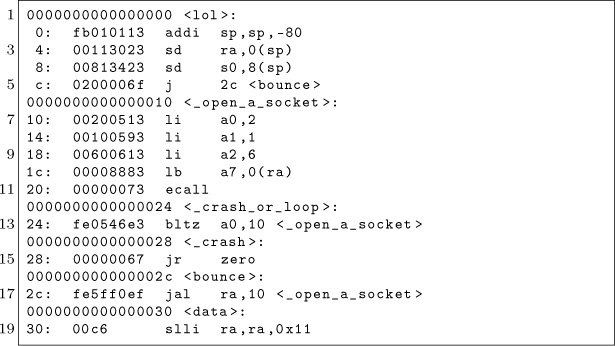
Putting it Together
The following example performs all actions described in previous sections. It allocates 80 bytes of memory on the stack, room for ten 64-bit words. It then uses the aforementioned bounce method to acquire the address of the static data stored in the payload. The system call for socket is then called by loading the arguments appropriately.
After the system call is issued, the return value is evaluated. If the socket call failed, and a negative value was returned, the _open_a_socket function is looped over.
If the socket call does succeed, which it likely will, the application will crash itself by calling a (presumably) non-existent function at virtual address 0x00000000.
As an example, the byte stored in static memory is loaded as part of the system call, only to demonstrate the ability to load code at specific offsets.
————
Big shout out to #plan9 for still existing after 17 years, TheNewSh for always rocking the mic, Travis Goodspeed for leading the modern zine revolution, RMinnich for being an excellent resource over the past decade, RPike for being an excellent role model, and my baby Pierce, for being my inspiration.
Source code and shellcode are available, of course.13
15:06 Cracking Gumball
by 4am and Peter Ferrie (qkumba, san inc)
Gumball is a 1983 arcade game by Robert Cook from a concept of Doug Carlston’s, published by Brøderbund Software. It runs on the Apple ][+ and later from a single-sided 5.25” floppy. Previously, it was cracked by Mr. Krac-Man and the Disk Jockey, along with other, uncredited releases. In this article, I’ll walk you through how I cracked the game, not so much to brag about it as to highlight the crazy tricks that it uses in its own defense.
Automated Tools Fail in Interesting Ways
Starting off with automated tools didn’t help much. COPYA immediately gave a disk read error, and Locksmith Fast Disk Backup couldn’t read any track, likely because this is not a 16-sector disk.
EDD 4-bit Copy seeks off of track zero, then hung with the drive motor on. This might be because early Brøderbund games loved using half tracks and quarter tracks, combined with runtime protection tracks.
Copy II+ Nibble Editor shows that T00 has a modified address prologue (D5 AA B5) and modified epilogues. T01+ appears to be 4-4 encoded, so that two nibbles on disk become one byte in memory, with a custom prologue/delimiter. In any case, it’s neither 13 nor 16 sectors.
This is decidedly not a single-load game: there is a classic crack that is a single binary, but it cuts out a lot of the introduction and some cut scenes later. All other cracks are whole-disk, multi-loaders. Combined with the early indications of a custom bootloader and 4-4 encoded sectors, this is not going to be a straightforward crack.
In Which We Brag About Our Humble Beginnings
I have two floppy drives, one in slot 6 and the other in slot 5. My “work disk” (in slot 5) runs Diversi-DOS 64K, which is compatible with Apple DOS 3.3 but relocates most of DOS to the language card on boot. This frees up most of main memory (only using a single page at $BF00..$BFFF), which is useful for loading large files or examining code that lives in areas typically reserved for DOS.
[S6,D1=original disk]
[S5,D1=my work disk]
The floppy drive code at $C600 is responsible for aligning the drive head and reading sector 0 of track 0 into main memory at $0800. Because the drive can be connected to any slot, the firmware code can’t assume it’s loaded at $C600. If the floppy drive card were removed from slot 6 and reinstalled in slot 5, the firmware code would load at $C500 instead.
To accommodate this, the firmware does some fancy stack manipulation to detect where it is in memory (which is a neat trick, since the 6502 program counter is not generally accessible). However, due to space constraints, the detection code only cares about the lower nibble of the high byte of its own address.
Stay with me, this is all about to come together and go boom.
$C600 (or $C500, or anywhere in $Cx00) is read-only memory. I can’t change it, which means I can’t stop it from transferring control to the boot sector of the disk once it’s in memory. BUT! The disk firmware code works unmodified at any address. Any address that ends with $x600 will boot slot 6, including $B600, $A600, $9600, &c.
*9600<C600.C6FFM Copy drive firmware to $9600.
*9600G Execute it.
…reboots slot 6, loads game…
Now then:
]PR#5 …
]CALL -151
*9600<C600.C6FFM
*96F8L
96F8 4C 01 08 JMP $0801
That’s where the disk controller ROM code ends and the on-disk code begins. But $9600 is part of read/write memory. I can change it at will. So I can interrupt the boot process after the drive firmware loads the boot sector from the disk but before it transfers control to the disk’s bootloader.
96F8 A0 00 LDY #$00 Instead of jumping to on-disk code, copy boot
96FA B9 00 08 LDA $0800,Y sector to higher memory so it survives a
96FD 99 00 28 STA $2800,Y reboot.
9700 C8 INY
9701 D0 F7 BNE $96FA
9703 AD E8 C0 LDA $C0E8 Turn off slot 6 drive motor.
9706 4C 00 C5 JMP $C500 Reboot to my work disk in slot 5.
*9600G
…reboots slot 6…
…reboots slot 5…
]BSAVE BOOT0,A$2800,L$100
Now we get to trace the boot process one sector, one page, one instruction at a time.0
We Dip Our Toes Into an Ocean of Raw Sewage
]CALL -151
*800<2800.28FFM Copy code back to $0800 where it was
801L originally loaded, to make it easier to follow.
0801 A2 00 LDX #$00 Immediately move this code to the input
0803 BD 00 08 LDA $0800,X buffer at $0200.
0806 9D 00 02 STA $0200,X
0809 E8 INX
080A D0 F7 BNE $0803
080C 4C 0F 02 JMP $020F
OK, I can do that too. Well, mostly. The page at $0200 is the text input buffer, used by both Applesoft BASIC and the built-in monitor (which I’m in right now). But I can copy enough of it to examine this code in situ.
*20F<80F.8FFM
*20FL
020F A0 AB LDY #$AB Set up a nibble translation table at $0800.
0211 98 TYA
0212 85 3C STA $3C
0214 4A LSR
0215 05 3C ORA $3C
0217 C9 FF CMP #$FF
0219 D0 09 BNE $0224
021B C0 D5 CPY #$D5
021D F0 05 BEQ $0224
021F 8A TXA
0220 99 00 08 STA $0800,Y
0223 E8 INX
0224 C8 INY
0225 D0 EA BNE $0211
0227 84 3D STY $3D
0229 84 26 STY $26 #$00 into zero page $26 and #$03 into $27
022B A9 03 LDA #$03 means we’re probably going to be loading data
022D 85 27 STA $27 into $0300..$03FF later, because ($26) points to
$0300.
022F A6 2B LDX $2B Zero page $2B holds the boot slot x16.
0231 20 5D 02 JSR $025D
*25DL
025D 18 CLC Read a sector from track $00 (this is actually
025E 08 PHP derived from the code in the disk controller
025F BD 8C C0 LDA $C08C,X ROM routine at $C65C, but looking for an
0262 10 FB BPL $025F address prologue of “D5 AA B5” instead of “D5
0264 49 D5 EOR #$D5 AA 96”) and using the nibble translation table
0266 D0 F7 BNE $025F we set up earlier at $0800.
0268 BD 8C C0 LDA $C08C,X
026B 10 FB BPL $0268
026D C9 AA CMP #$AA
026F D0 F3 BNE $0264
0271 EA NOP
0272 BD 8C C0 LDA $C08C,X
0275 10 FB BPL $0272
0277 C9 B5 CMP #$B5 #$B5 for third prologue nibble.
0279 F0 09 BEQ $0284
027B 28 PLP
027C 90 DF BCC $025D
027E 49 AD EOR #$AD
0280 F0 1F BEQ $02A1
0282 D0 D9 BNE $025D
0284 A0 03 LDY #$03
0286 84 2A STY $2A
0288 BD 8C C0 LDA $C08C,X
028B 10 FB BPL $0288
028D 2A ROL
028E 85 3C STA $3C
0290 BD 8C C0 LDA $C08C,X
0293 10 FB BPL $0290
0295 25 3C AND $3C
0297 88 DEY
0298 D0 EE BNE $0288
029A 28 PLP
029B C5 3D CMP $3D
029D D0 BE BNE $025D
029F B0 BD BCS $025E
02A1 A0 9A LDY #$9A
02A3 84 3C STY $3C
02A5 BC 8C C0 LDY $C08C,X
02A8 10 FB BPL $02A5
02AA 59 00 08 EOR $0800,Y Use the nibble translation table we set up
02AD A4 3C LDY $3C earlier to convert nibbles on disk into bytes in
02AF 88 DEY memory.
02B0 99 00 08 STA $0800,Y
02B3 D0 EE BNE $02A3
02B5 84 3C STY $3C
02B7 BC 8C C0 LDY $C08C,X
02BA 10 FB BPL $02B7
02BC 59 00 08 EOR $0800,Y
02BF A4 3C LDY $3C
02C1 91 26 STA ($26),Y Store the converted bytes at $0300.
02C3 C8 INY
02C4 D0 EF BNE $02B5
02C6 BC 8C C0 LDY $C08C,X Verify the data with a one-nibble checksum.
02C9 10 FB BPL $02C6
02CB 59 00 08 EOR $0800,Y
02CE D0 8D BNE $025D
02D0 60 RTS
Continuing from $0234. . .
*234L
0234 20 D1 02 JSR $02D1
*2D1L
02D1 A8 TAY Finish decoding nibbles.
02D2 A2 00 LDX #$00
02D4 B9 00 08 LDA $0800,Y
02D7 4A LSR
02D8 3E CC 03 ROL $03CC,X
02DB 4A LSR
02DC 3E 99 03 ROL $0399,X
02DF 85 3C STA $3C
02E1 B1 26 LDA ($26),Y
02E3 0A ASL
02E4 0A ASL
02E5 0A ASL
02E6 05 3C ORA $3C
02E8 91 26 STA ($26),Y
02EA C8 INY
02EB E8 INX
02EC E0 33 CPX #$33
02EE D0 E4 BNE $02D4
02F0 C6 2A DEC $2A
02F2 D0 DE BNE $02D2
02F4 CC 00 03 CPY $0300 Verify final checksum.
02F7 D0 03 BNE $02FC
02F9 60 RTS Checksum passed, return to caller and
continue with the boot process.
02FC 4C 2D FF JMP $FF2D Checksum failed, print “ ERR ” and exit.
Continuing from $0237…
0237 4C 01 03 JMP $0301 Jump into the code we just read.
This is where I get to interrupt the boot, before it jumps to $0301.
In Which We Do a Bellyflop Into a Decrypted Stack and Discover that I am Very Bad at Metaphors
*9600<C600.C6FFM
96F8 A9 05 LDA #$05 Patch boot0 so it calls my routine instead of
96FA 8D 38 08 STA $0838 jumping to $0301.
96FD A9 97 LDA #$97
96FF 8D 39 08 STA $0839
9702 4C 01 08 JMP $0801 Start the boot.
9705 A0 00 LDY #$00 (Callback is here.) Copy the code at $0300
9707 B9 00 03 LDA $0300,Y to higher memory so it survives a reboot.
970A 99 00 23 STA $2300,Y
970D C8 INY
970E D0 F7 BNE $9707
9710 AD E8 C0 LDA $C0E8 Turn off slot 6 drive motor and reboot to my
9713 4C 00 C5 JMP $C500 work disk in slot 5.
*BSAVE TRACE,A$9600,L$116
*9600G
…reboots slot 6…
…reboots slot 5…
]BSAVE BOOT1
0300-03FF,A$2300,L$100
]CALL -151
*2301L
2301 84 48 STY $48
2303 A0 00 LDY #$00 Clear hi-res graphics screen 2,
2305 98 TYA
2306 A2 20 LDX #$20
2308 99 00 40 STA $4000,Y
230B C8 INY
230C D0 FA BNE $2308
230E EE 0A 03 INC $030A
2311 CA DEX
2312 D0 F4 BNE $2308
2314 AD 57 C0 LDA $C057 and show it. (Appears blank.)
2317 AD 52 C0 LDA $C052
231A AD 55 C0 LDA $C055
231D AD 50 C0 LDA $C050
2320 B9 00 03 LDA $0300,Y Decrypt the rest of this page to the stack page
2323 45 48 EOR $48 at $0100.
2325 99 00 01 STA $0100,Y
2328 C8 INY
2329 D0 F5 BNE $2320
232B A2 CF LDX #$CF Set the stack pointer, and exit via RTS.
232D 9A TXS
232E 60 RTS
*9600<C600.C6FFM
96F8 A9 05 LDA #$05 Patch boot0 so it calls my routine instead of
96FA 8D 38 08 STA $0838 jumping to $0301.
96FD A9 97 LDA #$97
96FF 8D 39 08 STA $0839
9702 4C 01 08 JMP $0801 Start the boot.
9705 A0 00 LDY #$00 (Callback is here.) Copy the code at $0300 to
9707 B9 00 03 LDA $0300,Y higher memory so it survives a reboot.
970A 99 00 23 STA $2300,Y
970D C8 INY
970E D0 F7 BNE $9707
9710 AD E8 C0 LDA $C0E8 Turn off slot 6 drive motor and reboot to my
9713 4C 00 C5 JMP $C500 work disk in slot 5.
*BSAVE TRACE,A$9600,L$116
*9600G
…reboots slot 6…
…reboots slot 5…
]BSAVE BOOT1
0300-03FF,A$2300,L$100
]CALL -151
*2301L
2301 84 48 STY $48
2303 A0 00 LDY #$00 Clear hi-res graphics screen 2,
2305 98 TYA
2306 A2 20 LDX #$20
2308 99 00 40 STA $4000,Y
230B C8 INY
230C D0 FA BNE $2308
230E EE 0A 03 INC $030A
2311 CA DEX
2312 D0 F4 BNE $2308
2314 AD 57 C0 LDA $C057 and show it. (Appears blank.)
2317 AD 52 C0 LDA $C052
231A AD 55 C0 LDA $C055
231D AD 50 C0 LDA $C050
2320 B9 00 03 LDA $0300,Y Decrypt the rest of this page to the stack page
2323 45 48 EOR $48 at $0100.
2325 99 00 01 STA $0100,Y
2328 C8 INY
2329 D0 F5 BNE $2320
232B A2 CF LDX #$CF Set the stack pointer, and exit with RTS.
232D 9A TXS
232E 60 RTS
Oh joy, stack manipulation. The stack on an Apple ][ is just $100 bytes in main memory ($0100..$01FF) and a single byte register that serves as an index into that page. This allows for all manner of mischief—overwriting the stack page (as we’re doing here), manually changing the stack pointer (also doing that here), or even putting executable code directly on the stack.
The challenge is that I have no idea where execution continues next, because I don’t know what ends up on the stack page. I need to interrupt the boot again to see the decrypted data that ends up at $0100.
Mischief Managed
*BLOAD TRACE
[first part is the same as the
previous trace]
9705 84 48 STY $48 Reproduce the decryption loop, but store the
9707 A0 00 LDY #$00 result at $2100 so it survives a reboot.
9709 B9 00 03 LDA $0300,Y
970C 45 48 EOR $48
970E 99 00 21 STA $2100,Y
9711 C8 INY
9712 D0 F5 BNE $9709
9714 AD E8 C0 LDA $C0E8 Turn off drive motor and reboot to my work
9717 4C 00 C5 JMP $C500 disk.
*BSAVE TRACE2,A$9600,L$11A
*9600G
…reboots slot 6…
…reboots slot 5…
]BSAVE BOOT1
0100-01FF,A$2100,L$100
]CALL -151
The original code at $0300 manually reset the stack pointer to #$CF and exited via RTS. The Apple ][ will increment the stack pointer before using it as an index into $0100 to get the next address. (For reasons I won’t get into here, it also increments the address before passing execution to it.)

$012F + 1 = $0130, which is already in memory at $2130.
Code on the stack, another treat. (Remember, the stack is just a page in main memory. If you want to use that page for something else, it’s up to you to ensure that it doesn’t conflict with the stack functioning as a stack.)
*2130L
2130 A2 04 LDX #$04
2132 86 86 STX $86
2134 A0 00 LDY #$00
2136 84 83 STY $83
2138 86 84 STX $84
Now ($83) points to $0400.
213A A6 2B LDX $2B Get slot number. (x16)
213C BD 8C C0 LDA $C08C,X Find a 3-nibble prologue. (“BF D7 D5”)
213F 10 FB BPL $213C
2141 C9 BF CMP #$BF
2143 D0 F7 BNE $213C
2145 BD 8C C0 LDA $C08C,X
2148 10 FB BPL $2145
214A C9 D7 CMP #$D7
214C D0 F3 BNE $2141
214E BD 8C C0 LDA $C08C,X
2151 10 FB BPL $214E
2153 C9 D5 CMP #$D5
2155 D0 F3 BNE $214A
2157 BD 8C C0 LDA $C08C,X Read 4-4-encoded data.
215A 10 FB BPL $2157
215C 2A ROL
215D 85 85 STA $85
215F BD 8C C0 LDA $C08C,X
2162 10 FB BPL $215F
2164 25 85 AND $85
2166 91 83 STA ($83),Y Store in $0400 (text page, but it’s hidden right
2168 C8 INY now because we switched to hi-res graphics
2169 D0 EC BNE $2157 screen 2 at $0314).
216B 0E 00 C0 ASL $C000 Find a 1-nibble epilogue (“D4”).
216E BD 8C C0 LDA $C08C,X
2171 10 FB BPL $216E
2173 C9 D4 CMP #$D4
2175 D0 B9 BNE $2130
2177 E6 84 INC $84 Increment target memory page.
2179 C6 86 DEC $86 Decrement sector count (initialized at $0132),
217B D0 DA BNE $2157 and exit with RTS.
217D 60 RTS
Wait, what? Ah, we’re using the same trick we used to call this routine—the stack has been pre-filled with a series of return addresses. It’s time to return to the next one.
$03FF + 1 = $0400, and that’s where I get to interrupt the boot.
Seek and Ye Shall Find
*BLOAD TRACE2
.
. [same as previous trace]
.
9705 84 48 STY $48 Reproduce the decryption loop that was
9707 A0 00 LDY #$00 originally at $0320.
9709 B9 00 03 LDA $0300,Y
970C 45 48 EOR $48
970E 99 00 01 STA $0100,Y
9711 C8 INY
9712 D0 F5 BNE $9709
9714 A9 21 LDA #$21 Now that the stack is in place at $0100, change
9716 8D D2 01 STA $01D2 the first return address so it points to a
9719 A9 97 LDA #$97 callback under my control (instead of
971B 8D D3 01 STA $01D3 continuing to $0400).
971E A2 CF LDX #$CF Continue the boot.
9720 9A TXS
9721 60 RTS
9722 A2 04 LDX #$04 (Callback is here.) Copy the contents of the
9724 A0 00 LDY #$00 text page to higher memory.
9726 B9 00 04 LDA $0400,Y
9729 99 00 24 STA $2400,Y
972C C8 INY
972D D0 F7 BNE $9726
972F EE 28 97 INC $9728
9732 EE 2B 97 INC $972B
9735 CA DEX
9736 D0 EE BNE $9726
9738 AD E8 C0 LDA $C0E8 Turn off the drive and reboot to my work disk.
973B 4C 00 C5 JMP $C500
*BSAVE TRACE3,A$9600,L$13E
*9600G
…reboots slot 6…
…reboots slot 5…
]BSAVE BOOT1
0400-07FF,A$2400,L$400
]CALL -151
I’m going to leave this code at $2400, since I can’t put it on the text page and examine it at the same time. Relative branches will look correct, but absolute addresses will be off by $2000.
*2400L
2400 A0 00 LDY #$00 Copy three pages to the top of main memory.
2402 B9 00 05 LDA $0500,Y
2405 99 00 BD STA $BD00,Y
2408 B9 00 06 LDA $0600,Y
240B 99 00 BE STA $BE00,Y
240E B9 00 07 LDA $0700,Y
2411 99 00 BF STA $BF00,Y
2414 C8 INY
2415 D0 EB BNE $2402
I can replicate that.
*FE89G FE93G ; disconnect DOS
*BD00<2500.27FFM ; simulate
copy loop
2417 A6 2B LDX $2B
2419 8E 66 BF STX $BF66
241C 20 48 BF JSR $BF48
*BF48L
BF48 AD 81 C0 LDA $C081 Zap contents of language card.
BF4B AD 81 C0 LDA $C081
BF4E A0 00 LDY #$00
BF50 A9 D0 LDA #$D0
BF52 84 A0 STY $A0
BF54 85 A1 STA $A1
BF56 B1 A0 LDA ($A0),Y
BF58 91 A0 STA ($A0),Y
BF5A C8 INY
BF5B D0 F9 BNE $BF56
BF5D E6 A1 INC $A1
BF5F D0 F5 BNE $BF56
BF61 2C 80 C0 BIT $C080
BF64 60 RTS
Continuing from $041F…
241F AD 83 C0 LDA $C083 Set low-level reset vectors and page 3 vectors
2422 AD 83 C0 LDA $C083 to point to $BF00—presumably The Badlands,
2425 A0 00 LDY #$00 from which there is no return.
2427 A9 BF LDA #$BF
2429 8C FC FF STY $FFFC
242C 8D FD FF STA $FFFD
242F 8C F2 03 STY $03F2
2432 8D F3 03 STA $03F3
2435 A0 03 LDY #$03
2437 8C F0 03 STY $03F0
243A 8D F1 03 STA $03F1
243D 84 38 STY $38
243F 85 39 STA $39
2441 49 A5 EOR #$A5
2443 8D F4 03 STA $03F4
*BE00L
BF00 A9 D2 LDA #$D2 There are multiple entry points here: $BF00,
BF02 2C A9 D0 BIT $D0A9 $BF03, $BF06, and $BF09 (hidden in this listing
BF05 2C A9 CC BIT $CCA9 by the “BIT” opcodes).
BF08 2C A9 A1 BIT $A1A9
BF0B 48 PHA
BF0C 20 48 BF JSR $BF48 Zap the language card again.
BF0F 20 2F FB JSR $FB2F TEXT/HOME/NORMAL
BF12 20 58 FC JSR $FC58
BF15 20 84 FE JSR $FE84
BF18 68 PLA Depending on the initial entry point, this
BF19 8D 00 04 STA $0400 displays a different character in the top left
corner of the screen.
BF1C A0 00 LDY #$00 Now wipe all of main memory,
BF1E 98 TYA
BF1F 99 00 BE STA $BE00,Y
BF22 C8 INY
BF23 D0 FA BNE $BF1F
BF25 CE 21 BF DEC $BF21
BF28 2C 30 C0 BIT $C030 while playing a sound.
BF2B AD 21 BF LDA $BF21
BF2E C9 08 CMP #$08
BF30 B0 EA BCS $BF1C
BF32 8D F3 03 STA $03F3 Munge the reset vector,
BF35 8D F4 03 STA $03F4
BF38 AD 66 BF LDA $BF66 and reboot from whence we came.
BF3B 4A LSR
BF3C 4A LSR
BF3D 4A LSR
BF3E 4A LSR
BF3F 09 C0 ORA #$C0
BF41 E9 00 SBC #$00
BF43 48 PHA
BF44 A9 FF LDA #$FF
BF46 48 PHA
BF47 60 RTS
Yeah, let’s try not to end up there.
Continuing from $0446…
2446 A9 07 LDA #$07
2448 20 00 BE JSR $BE00
*BE00L
BE00 A2 13 LDX #$13 Entry Point #1
BE02 2C A2 0A BIT $0AA2 Entry Point #2. (Hidden behind a BIT opcode,
but it’s “LDX #$0A”.)
BE05 8E 6E BE STX $BE6E ![]() Modify the code later based on which entry
Modify the code later based on which entry
point we called.
BE08 8D 90 BE STA $BE90 The rest of this routine is a garden variety
BE0B CD 65 BF CMP $BF65 drive seek. The target phase (track × 2) is in
BE0E F0 59 BEQ $BE69 the accumulator on entry.
BE10 A9 00 LDA #$00
BE12 8D 91 BE STA $BE91
BE15 AD 65 BF LDA $BF65
BE18 8D 92 BE STA $BE92
BE1B 38 SEC
BE1C ED 90 BE SBC $BE90
BE1F F0 37 BEQ $BE58
BE21 B0 07 BCS $BE2A
BE23 49 FF EOR #$FF
BE25 EE 65 BF INC $BF65
BE28 90 05 BCC $BE2F
BE2A 69 FE ADC #$FE
BE2C CE 65 BF DEC $BF65
BE2F CD 91 BE CMP $BE91
BE32 90 03 BCC $BE37
BE34 AD 91 BE LDA $BE91
BE37 C9 0C CMP #$0C
BE39 B0 01 BCS $BE3C
BE3B A8 TAY
BE3C 38 SEC
BE3D 20 5C BE JSR $BE5C
BE40 B9 78 BE LDA $BE78,Y
BE43 20 6D BE JSR $BE6D
BE46 AD 92 BE LDA $BE92
BE49 18 CLC
BE4A 20 5F BE JSR $BE5F
BE4D B9 84 BE LDA $BE84,Y
BE50 20 6D BE JSR $BE6D
BE53 EE 91 BE INC $BE91
BE56 D0 BD BNE $BE15
BE58 20 6D BE JSR $BE6D
BE5B 18 CLC
BE5C AD 65 BF LDA $BF65
BE5F 29 03 AND #$03
BE61 2A ROL
BE62 0D 66 BF ORA $BF66
BE65 AA TAX
BE66 BD 80 C0 LDA $C080,X
BE69 AE 66 BF LDX $BF66
BE6C 60 RTS
BE6D A2 13 LDX #$13 (The value of X may be modified depending
BE6F CA DEX on which entry point was called.)
BE70 D0 FD BNE $BE6F
BE72 38 SEC
BE73 E9 01 SBC #$01
BE75 D0 F6 BNE $BE6D
BE77 60 RTS
BE78 [01 30 28 24 20 1E 1D 1C]
BE80 [1C 1C 1C 1C 70 2C 26 22]
BE88 [1F 1E 1D 1C 1C 1C 1C 1C]
The fact that there are two entry points is interesting. Calling $BE00 will set X to #$13, which will end up in $BE6E, so the wait routine at $BE6D will wait long enough to go to the next phase (a.k.a. half a track). Nothing unusual there; that’s how all drive seek routines work. But calling $BE03 instead of $BE00 will set X to #$0A, which will make the wait routine burn fewer CPU cycles while the drive head is moving, so it will only move half a phase (a.k.a. a quarter track). That is potentially very interesting.
Continuing from $044B…
244B A9 05 LDA #$05
244D 85 33 STA $33
244F A2 03 LDX #$03
2451 86 36 STX $36
2453 A0 00 LDY #$00
2455 A5 33 LDA $33
2457 84 34 STY $34
2459 85 35 STA $35
Now ($34) points to $0500.
245B AE 66 BF LDX $BF66 Find a 3-nibble prologue (“B5 DE F7”).
245E BD 8C C0 LDA $C08C,X
2461 10 FB BPL $245E
2463 C9 B5 CMP #$B5
2465 D0 F7 BNE $245E
2467 BD 8C C0 LDA $C08C,X
246A 10 FB BPL $2467
246C C9 DE CMP #$DE
246E D0 F3 BNE $2463
2470 BD 8C C0 LDA $C08C,X
2473 10 FB BPL $2470
2475 C9 F7 CMP #$F7
2477 D0 F3 BNE $246C
2479 BD 8C C0 LDA $C08C,X Read 4-4-encoded data into $0500+.
247C 10 FB BPL $2479
247E 2A ROL
247F 85 37 STA $37
2481 BD 8C C0 LDA $C08C,X
2484 10 FB BPL $2481
2486 25 37 AND $37
2488 91 34 STA ($34),Y
248A C8 INY
248B D0 EC BNE $2479
248B D0 EC BNE $2479
248D 0E FF FF ASL $FFFF
2490 BD 8C C0 LDA $C08C,X Find a 1-nibble epilogue (“D5”).
2493 10 FB BPL $2490
2495 C9 D5 CMP #$D5
2497 D0 B6 BNE $244F
2499 E6 35 INC $35
249B C6 36 DEC $36 3 sectors (initialized at $0451)
249D D0 DA BNE $2479
249F 60 RTS Exit via RTS.
We’ve read three more sectors into $0500+, overwriting the code we read earlier (but moved to $BD00+), and once again we simply exit and let the stack tell us where we’re going next.

$04FF + 1 = $0500, the code we just read. And that’s where I get to interrupt the boot.
Return of the Jedi
. *C500G Reboot because I disconnected and overwrote
… DOS to examine the previous code chunk at
]CALL -151 $BD00+
*BLOAD TRACE3
.
. [same as previous trace]
.
9714 A9 21 LDA #$21 Patch the stack again, but slightly later, at
9716 8D D4 01 STA $01D4 $01D4. (The previous trace patched it at
9719 A9 97 LDA #$97 $01D2.)
971B 8D D5 01 STA $01D5
971E A2 CF LDX #$CF Continue the boot.
9720 9A TXS
9721 60 RTS
9722 A2 04 LDX #$03 (Callback is here.) We just executed all the
9724 A0 00 LDY #$00 code up to and including the “RTS” at $049F, so
9726 B9 00 05 LDA $0500,Y now let’s copy the latest code at $0500..$07FF
9729 99 00 25 STA $2500,Y to higher memory so it survives a reboot.
972C C8 INY
972D D0 F7 BNE $9726
972F EE 28 97 INC $9728
9732 EE 2B 97 INC $972B
9735 CA DEX
9736 D0 EE BNE $9726
9738 AD E8 C0 LDA $C0E8 Reboot to my work disk.
973B 4C 00 C5 JMP $C500
*BSAVE TRACE4,A$9600,L$13E
*9600G
…reboots slot 6…
…reboots slot 5…
]BSAVE BOOT2
0500-07FF,A$2500,L$300
]CALL -151
Again, I’m going to leave this at $2500 because I can’t examine code on the text page. Relative branches will look correct, but absolute addresses will be off by $2000.
*2500L
2500 A9 02 LDA #$02 Seek to track 1.
2502 20 00 BE JSR $BE00
2505 AE 66 BF LDX $BF66 Get slot number x16, set a long time ago, at
2508 A0 00 LDY #$00 $0419).
250A A9 20 LDA #$20
250C 85 30 STA $30
250E 88 DEY
250F D0 04 BNE $2515
2511 C6 30 DEC $30
2513 F0 3C BEQ $2551
2515 BD 8C C0 LDA $C08C,X Find a 3-nibble prologue. (“D5 FF DD”)
2518 10 FB BPL $2515
251A C9 D5 CMP #$D5
251C D0 F0 BNE $250E
251E BD 8C C0 LDA $C08C,X
2521 10 FB BPL $251E
2523 C9 FF CMP #$FF
2525 D0 F3 BNE $251A
2527 BD 8C C0 LDA $C08C,X
252A 10 FB BPL $2527
252C C9 DD CMP #$DD
252E D0 F3 BNE $2523

2530 A0 00 LDY #$00 Read 4-4-encoded data
2532 BD 8C C0 LDA $C08C,X
2535 10 FB BPL $2532
2537 38 SEC
2538 2A ROL
2539 85 30 STA $30
253B BD 8C C0 LDA $C08C,X
253E 10 FB BPL $253B
2540 25 30 AND $30
2542 99 00 B0 STA $B000,Y into $B000. Hard-coded here, was not modified
2545 C8 INY earlier unless I missed something.
2546 D0 EA BNE $2532
2548 BD 8C C0 LDA $C08C,X Find a 1-nibble epilogue (“D5”).
254B 10 FB BPL $2548
254D C9 D5 CMP #$D5
254F F0 0B BEQ $255C
2551 A0 00 LDY #$00 This is odd. If the epilogue doesn’t match, it’s
2553 B9 00 07 LDA $0700,Y not an error. Instead, it appears that we
2556 99 00 B0 STA $B000,Y simply copy a page of data that we read
2559 C8 INY earlier (at $0700).
255A D0 F7 BNE $2553
255C 20 F0 05 JSR $05F0 Execution continues here regardless.
*25F0L
25F0 A0 56 LDY #$56 Weird, but OK. This ends up calling $BE00
25F2 A9 BD LDA #$BD with A=$07, which will seek to track 3.5.
25F4 48 PHA
25F5 A9 FF LDA #$FF
25F7 48 PHA
25F8 A9 07 LDA #$07
25FA 60 RTS
And now we’re on half tracks.

Continuing from $055F…
255F BD 8C C0 LDA $C08C,X Find a 3-nibble prologue (DD EF AD).
2562 10 FB BPL $255F
2564 C9 DD CMP #$DD
2566 D0 F7 BNE $255F
2568 BD 8C C0 LDA $C08C,X
256B 10 FB BPL $2568
256D C9 EF CMP #$EF
256F D0 F3 BNE $2564
2571 BD 8C C0 LDA $C08C,X
2574 10 FB BPL $2571
2576 C9 AD CMP #$AD
2578 D0 F3 BNE $256D
257A A0 00 LDY #$00 Read a 4-4 encoded byte, where two nibbles on
257C BD 8C C0 LDA $C08C,X disk form one byte in memory.
257F 10 FB BPL $257C
2581 38 SEC
2582 2A ROL
2583 85 00 STA $00
2585 BD 8C C0 LDA $C08C,X
2588 10 FB BPL $2585
258A 25 00 AND $00
258C 48 PHA Push that byte to the stack. (WTF?)
258D 88 DEY Repeat for $100 bytes.
258E D0 EC BNE $257C
2590 BD 8C C0 LDA $C08C,X Find a 1-nibble epilogue (D5).
2593 10 FB BPL $2590
2595 C9 D5 CMP #$D5
2597 D0 C3 BNE $255C
2599 CE 9C 05 DEC $059C ![]()
259C 61 00 ADC ($00,X)
![]() Self-modifying code alert! WOO WOO. I’ll use this symbol whenever one instruction modifies the next instruction. When this happens, the disassembly listing is misleading because the opcode will be changed by the time the second instruction is executed.
Self-modifying code alert! WOO WOO. I’ll use this symbol whenever one instruction modifies the next instruction. When this happens, the disassembly listing is misleading because the opcode will be changed by the time the second instruction is executed.
In this case, the DEC at $0599 modifies the opcode at $059C, so that’s not really an ADC. By the time we execute the instruction at $059C, it will have been decremented to #$60, a.k.a. RTS.
One other thing: we’ve read $100 bytes and pushed all of them to the stack. The stack is only $100 bytes ($0100..$01FF), so this completely obliterates any previous values.
We haven’t changed the stack pointer, though. That means the RTS at $059C will still look at $01D6 to find the next return address. That used to be 4F 04, but now it’s been overwritten with new values, along with the rest of the stack. That’s some serious Jedi mind trick stuff.
In Which We Move Along
Luckily, there’s plenty of room at $0599. I can insert a JMP to call back to code under my control, where I can save a copy of the stack. (And $B000 as well, whatever that is.) I get to ensure I don’t disturb the stack before I save it, so no JSR, PHA, PHP, or TXS. I think I can manage that. JMP doesn’t disturb the stack, so that’s safe for the callback.
*BLOAD TRACE4
.
. [same as previous trace]
.
9722 A9 4C LDA #$4C Set up a JMP $9734 at $0599.
9724 8D 99 05 STA $0599
9727 A9 34 LDA #$34
9729 8D 9A 05 STA $059A
972C A9 97 LDA #$97
972E 8D 9B 05 STA $059B
9731 4C 00 05 JMP $0500 Continue the boot.

9734 A0 00 LDY #$00 (Callback is here.) Copy $B000 and $0100 to
9736 B9 00 B0 LDA $B000,Y higher memory so they survive a reboot.
9739 99 00 20 STA $2000,Y
973C B9 00 01 LDA $0100,Y
973F 99 00 21 STA $2100,Y
9742 C8 INY
9743 D0 F1 BNE $9736
9745 AD E8 C0 LDA $C0E8 Reboot to my work disk.
9748 4C 00 C5 JMP $C500
*BSAVE TRACE5,A$9600,L$14B
*9600G
…reboots slot 6…
…reboots slot 5…
]BSAVE BOOT2
B000-B0FF,A$2000,L$100
]BSAVE BOOT2
0100-01FF,A$2100,L$100
]CALL -151
Remember, the stack pointer hasn’t changed. Now that I have the new stack data, I can just look at the right index in the captured stack page to see where the bootloader continues once it issues the RTS at $059C. That’s part of the stack page I just captured, so it’s already in memory.

Next up we have another disk read routine! The fourth? Fifth? I’ve truly lost count.
*2126L
2126 BD 8C C0 LDA $C08C,X Find a 3-nibble prologue. (BF BE D4)
2129 10 FB BPL $2126
212B C9 BF CMP #$BF
212D D0 F7 BNE $2126
212F BD 8C C0 LDA $C08C,X
2132 10 FB BPL $212F
2134 C9 BE CMP #$BE
2136 D0 F3 BNE $212B
2138 BD 8C C0 LDA $C08C,X
213B 10 FB BPL $2138
213D C9 D4 CMP #$D4
213F D0 F3 BNE $2134
2141 A0 00 LDY #$00 Read 4-4-encoded data.
2143 BD 8C C0 LDA $C08C,X
2146 10 FB BPL $2143
2148 38 SEC
2149 2A ROL
214A 8D 00 02 STA $0200
214D BD 8C C0 LDA $C08C,X
2150 10 FB BPL $214D
2152 2D 00 02 AND $0200
2155 59 00 01 EOR $0100,Y Decrypt the data from disk by using this
entire page of code in the stack page as the
decryption key. (More on this later.)
2158 99 00 00 STA $0000,Y Store it in zero page.
215B C8 INY
215C D0 E5 BNE $2143
215E BD 8C C0 LDA $C08C,X Find a 1-nibble epilogue. (D5)
2161 10 FB BPL $215E
2163 C9 D5 CMP #$D5
2165 D0 BF BNE $2126
2167 60 RTS Exit via RTS.
And we’re back on the stack again. The six 57 FF words and the following 22 01 word are the next return addresses.
*21D0.
21D0 F0 78 AD D8 02 85 25 01
21D8 57 FF 57 FF 57 FF 57 FF
21E0 57 FF 22 01 FF 05 B1 4C
$FF57 +1 = $FF58, which is a well-known address in ROM that is always an RTS instruction. So this will burn through several return addresses on the stack in short order, then finally arrive at $0123, in memory at $2123.
*2123L
2123 6C 28 00 JMP ($0028)
...which is in the new zero page that was just read from disk.
And to think, we’ve loaded basically nothing of consequence yet. The screen is still black. We have three pages of code at $BD00..$BFFF. There’s still some code on the text screen, but who knows if we’ll ever call it again. Now we’re off to a zero page for some reason.
Unbelievable.