The IEEE (1994) defines validation as
"the process of evaluating a system or component during or at the end of the development process to determine whether it satisfies specified requirements" (IEEE 1012-1986, §2, 1994).
In other words, use validation to confirm that the implemented system conforms to the requirements we've established.
But this definition doesn't go far enough. Although testing to the requirements is certainly an important step, there is still a chance that the system we deliver may not be what the customer wanted. We've seen projects on which much time and effort were expended on making sure that the customer's needs were collected and understood, followed by an implementation effort that prepared a system shown (by validation tests) to correctly meet all of the collected requirements, followed by delivering the final product to the customer, who balked and said that the product was not what was wanted.
What went wrong? Simple. The project failed to move the nebulous "cloud" of the user's problem into alignment with the proxy represented by the requirements. However, this is of small comfort to the project team that has just made heroic sacrifices to deliver the product. Performing acceptance tests at each iteration will minimize this syndrome.
Acceptance tests bring the customer into the final validation process in order to gain assurance that "the product works the way the customer really needs it to." In an outsourcing environment, acceptance testing may be developed and executed as part of the contract provisions. In an IS/IT or ISV environment, the value provided by acceptance tests is more typically accomplished by the customer alpha or beta evaluation process.
Acceptance tests are typically based on a specific number of "scenarios" that the user specifies and executes in the usage environment. Thus, the customer has freedom to think "outside the box" and has license to construct interesting ways to test the system in order to gain confidence that the system works as needed. If we've done our job right, the acceptance test will be based on certain key use cases that we've already defined and implemented. But the acceptance test should also apply these use cases in interesting combinations and under the types of system load and other environmental factors—interoperability with other applications, OS dependencies, and so on—that are likely to be present in the user's environment.
In an iterative development process, generations of acceptance tests should be run at the various construction milestones, so the final acceptance test should not bring any significant surprises to the development team. In a more waterfall-like model, this is often not the case, and major surprises are routine. In any model, it's never too late to discover at least a few "Undiscovered Ruins" that will still need to be addressed. In Chapter 34, we'll talk about how to manage changes that this may occasion.
The primary activities in validation are testing activities. But what does a good test plan look like? For one answer, the IEEE 829-1983, IEEE Standard for Software Test Documentation (IEEE 1994) provides eight document templates that offer guidance on the establishment of a test methodology, conducting tests, reporting results, and resolving anomalies. Other guidelines (Rational 1999) have somewhat different approaches, but most agree on a few key elements.
Your development process must include planning for test activities. (In the iterative model, most test planning is done in the elaboration phase.)
Your development process must also provide time and resources to design the tests. It helps to have an overall template designed so that each individual test design can be largely a matter of plugging in the individual test details.
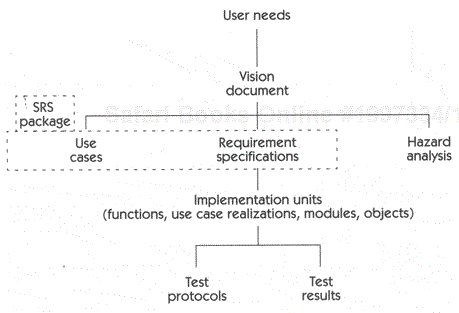
Your development must also provide time and resources to execute the tests, both at the unit test level (as required) and at the overall system level. The test documents form part of the implementation documentation. Allowing for test documents, the implementation documentation tree should appear as in Figure 32-1.
We recommend that you maintain an audit trail between the validation/testing activities and the specifications for that implementation. This audit trail is provided by traceability.
Validation traceability gives you confidence that two important goals have been addressed.
Do we have enough tests to cover everything that needs testing?
Do we have any extra or gratuitous tests that serve no useful purpose?
Validation focuses on whether the product works as it is supposed to. We are no longer inspecting the relationships of the various specification and design elements but instead are considering the relationships between the tests (and test results) and the system being tested. As in verification, the object is to ensure that all relevant elements are tested for conformance to the requirements.
But what is a "relevant element"? What do you test? One common approach is to test the product against its implementation. That is, many projects approach testing with a mind set that says, "Here is an implementation feature, say, the database manager, so let's test it by banging away on the database manager interfaces." Although this may be an appropriate test, it covers only half the job.
Quality can be achieved only by testing the system against its requirements. Yes, it may be useful to perform unit tests against various project elements such as the database manager, but we have found that unit tests rarely give you the needed assurance that the entire system works as required. Indeed, many complex projects are often found to pass all of the unit tests but to fail as a system. Why? Because the units interact in more complex behaviors, and the resulting system has not been adequately tested against the governing system requirements.
Let's examine how we can use the techniques we developed for verification in the execution of the system validation activities. We'll turn again to our case study.
Writing test cases, like collecting requirements, is both an art and a science. Although we won't examine the matter too deeply, it is instructive to get at least a top-level view of how the test cases can be derived from the functionality expressed by the use cases and the requirements we collected to define the system. For this example, we'll return to our case study and use the Control Light use case that we developed in Team Skill 5.
Table 32–1 is a sample test case for the Control Light use case. Test Case 1, used to test instances of the use case Control Light, is used only to test Control Switch buttons that have been preassigned to a light bank that is dim-enabled.
Test Case 1 focuses on testing interactions with the system that closely mimic the real-world flow of events that we spelled out in the Control Light use case. So, the use case served as a template for how to test the system. This is one of the major benefits of the use-case technique.
The unabbreviated version of this test case appears in Appendix A with the other HOLIS artifacts. Test Case 2 in Appendix A is an example that tests an aggregate set of discrete requirements rather than a single use case test. We'll visit Test Case 2 and its relationship to the software requirements shortly. Both Test Case 1 and Test Case 2 are the subjects of the following traceability discussion.
Traceability techniques allow us to easily confirm that the test cases cover the required functionality of the system. We simply need to construct a series of test plans that we can link back to the original system requirements and use cases.
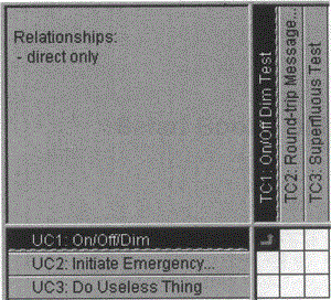
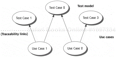
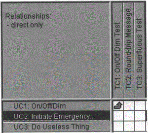
For example, suppose we had a traceability matrix that compared tests to the use cases (see Figure 32–2). Just as in the verification activities, we can examine the matrix to ensure proper coverage of the test cases versus the system specifications. Similarly, we can compare use cases against test cases, as shown in Figure 32–3.
Table 32-1. Test Case 1 (simplified)
| Test Case ID | Event Description | Input 1 | Input 2 | Expected Result |
|---|---|---|---|---|
| Basic flow | ||||
| 2001 | Resident presses Control Switch (CS). | Any enabled button | Light was on before button was pressed (tested must record level). | Light is turned off. |
| 2002 | Light was off before button was pressed. | Light is turned on to OnLevel. | ||
| 2003 | Resident releases button in less than 1 second. | Light on | Stays off. | |
| 2005 | Resident releases button in less than 1 second. (This ends path 1 through use case.) | Light off | Stays on at OnLevel. | |
| 2006 | Resident presses button again and releases it in less than 1 second. | Same enabled button as in 2003 | Light off before | Light is turned on to same illumination level as in 2002. |
| Resident presses button again and releases it in less than 1 second. | Light on before | Light is turned off. | ||
| Alternative flow | ||||
| 2007 | Button held longer than 1 second. | Enabled button | Light off before | Light turned on. Brightness increases 10% to maximum level for each second held, then decreases 10% for each second held until minimum reached, then increases again. Cycles continuously while held. |
| 2008 | Resident releases button. | Brightness held at last reached level. | ||
| Note: Run test case multiple times and with different lenghts of hold-button time to verify that system is restoring OnLevel properly. | ||||
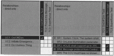
In the same way that we used traceability relationships to relate use cases to test cases, we can use traceability to manage relationships between discrete, or itemized requirements and to then associate them with test cases. Figure 32–4 shows a fragment of a test case specification traceability matrix. Note that Test Case 2 ("TC2: Round-trip message") has appeared and is linked to the software requirements of the HOLIS SRS package. Note also that we treat test cases no differently from the other types of elements we have traced in our verification and validation activities.
So far, we have linked the test cases into the traceability matrices. Now it's time to examine the linkages as we did it in the verification inspections.
Once again, you are looking for cases in which the rows of the traceability matrix show you that a particular feature or requirement is not linked to a software test. In Figure 32–5, for example, Use Case 2 (UC2) is not linked to any test case (TC). (UC3 links are missing also, but our verification activities already decided that the use case should never have been in there at all.)
Having detected this "hole" in the relationships, you should review the original set of product requirements and the related test cases.
If you find that a link was accidentally missed in establishing the traceability, simply add a new link and recompute the trace matrix. This type of omission frequently occurs in the early stages of establishing validation traceability.
If you find that the development of the software test cases simply failed to test one of the required product features, you may need a project review to consider the addition of suitable tests to respond to the product feature. Unlike the similar case in verification activities, we do not recommend marking the missing test case as a "future" activity. If there is an untested feature, you may be assured that your customer will test it, often with grievous consequences! Also, regulated developments, such as FDA regulation of a medical product, will not accept the postponement of necessary tests.
Validation traceability helps ensure that no linkages have been left out and that all product tests have been properly related to the higher-level product requirements. Of course, it also helps if the product passes the tests!
As with verification, validation may also uncover the opposite issue. That is, inspection of the columns of the trace matrix may reveal a column that is not linked to any row elements. In Figure 32–5, for example, Test Case 3 (TC3) is not linked to any use case. We also know from Figure 32–4 that it is not linked to any software requirement. This type of situation indicates that you have created a test for which there was no related product feature. That is, the test appears to be superfluous to the product features. As before, you should review the trace relationships.
Perhaps a link was accidentally missed in establishing the traceability. If so, simply add a new link and recompute the trace matrix. This type of omission frequently occurs in the early stages of establishing validation traceability.
Or, you might find that the development of the product features simply failed to consider the needs of one of the required software tests. This case may occur if, for example, certain nonfunctional requirements for the implementation in fact change the features of the product. In this case, a project review may be necessary to consider the feasibility and need for the requirements. As in verification, your team will need to resolve whether the test is required at all and, if it is, what traceability linkages are needed.
OK, so you know how to collect and manage the tests for the use cases and requirements. The question then arises, "How do you test design constraints?"
In Team Skill 5, we discussed the fact that although design constraints are unique, the easiest way to treat them is to simply consider them requirements. That is, we trace their linkages in the same way, and we verify them in the same way. Therefore, it is appropriate to include design constraints as part of the validation effort. When it comes to testing, you should test design constraints just as you would anything else. Many design constraints will yield to a simple test by inspection. For example, a design constraint that requires the software to be written in Visual Basic (VB) can be tested by simply looking at the source code.
Since many design constraints will yield to simple inspections, you should consider having an abbreviated test procedure for such inspection matters. There is no need to have a complicated form listing the calibrated equipment needed, setup procedures, environmental setups, and so on. Instead, just have a simple form saying that you have inspected the code or other artifact and found it to be in conformance with the design constraint. Some sample approaches to testing design constraints are shown in Table 32–2.
Table 32-2. Design constraint validation approaches
| Design Constraint | Validation Approach |
|---|---|
| "Write the software in VB 5.0" | Inspect source code. |
| "The application must be based on the architectural patterns from the Fuji Project." | Identify patterns in Fuji design models; compare with current project design. |
| "Use the Developer's Library 99-724 class library from XYZ Corporation." | Inspect ordering and receiving records, product documentation supplied, and revision numbers; inspect that libraries are properly loaded and properly used. |
Verification is an analytical process that works throughout the project to ensure that you are doing the right things. Validation ensures that the system works as it is supposed to, both in conforming to the customer's documented requirements and in the actual usage scenario. Together, verification and validation help assure the team that they are indeed "Building the Right System Right."
But, we've left something out. You might be wondering, "How do I decide on how much V&V work to do?" Let's look at that question in the next chapter.

