
REPAIRING AND EXPORTING
REPAIRING A FILE WITH MESHMIXER
REPAIRING A FILE WITH NETFABB BASIC

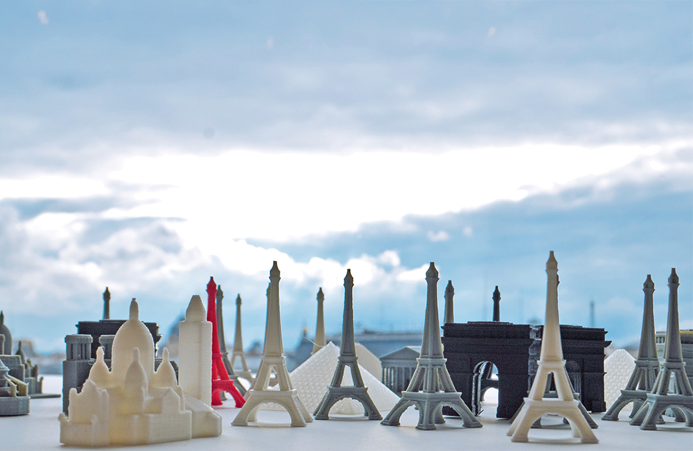
MINIATURE PARIS
The web is rich in 3D content: there are models of cars, furniture, plants, and even characters from video games... The web probably has what you need. Sometimes these models have a price and sometimes they’re free, but the files you can get are rarely ready for 3D printing, unfortunately, because a majority of these files are designed as graphics (not things), whether to create synthesized images, animation, or even architectural layout plans.
The collection of Paris’s miniature monuments is an example of some open source architecture files that have been misused with the aim of being printed. Originally created for Google Earth’s 3D view, the buildings were downloaded for free on the SketchUp Warehouse platform. The original files, containing hundreds of design errors, such as walls that were too thin, all had to be corrected before being printed on a miniature scale.
This project, completed by le FabShop, had the goal of creating a souvenir collection of Parisian architecture. Each mini-monument, placed inside a small sphere of crystalline plastic, was distributed by a “gumball machine” during the first Maker Faire Paris. The family still needs to be completed with other classics, such as the Moulin Rouge, or the Montparnasse tower, but you can already download the Eiffel Tower, the Arc de Triomphe, Sacre Coeur, Notre Dame, La Madeleine, and the Pyramids of the Louvre at the following address:
http://www.thingiverse.com/thing:311002

Paris miniature
3D printed on: Replicator 2
By: le FabShop
Source: le FabShop
© Océane Delain
Source: Thingiverse
Thing: 311002
Notre-Dame miniature
3D printed on: Replicator 2
By: le FabShop
Source: le FabShop
© Océane Delain
Source: Thingiverse
Thing: 311002
Eiffel Tower miniature
3D printed on: Replicator 2
By: le FabShop
Source: le FabShop
© le FabShop
Source: Thingiverse
Thing: 311002
REPAIRING AN STL FILE
In order to be used in 3D printing, a file must meet certain criteria (see pp. 22-23).
If you aren’t the author of the 3D model and if it wasn’t created for digital production, there’s a strong possibility that it won’t meet one of these criteria.
Here are the most common problems:
![]() Reversed normals (Part of the mesh facing in the wrong direction)
Reversed normals (Part of the mesh facing in the wrong direction)
![]() Open surface
Open surface
![]() Collision between volumes
Collision between volumes
![]() Non-aligned edges
Non-aligned edges
![]() Bad file type
Bad file type
![]() Wrong scale
Wrong scale
There’s a chance that you won’t find a solution for a model that you didn’t create yourself. Fortunately, there is software to solve some of these problems, without having to go back to the model’s original source file. Nothing is perfect, because a lot of files are quite simply too corrupt to be recovered, but some distinguish themselves by being remarkably effective. The most effective of them all is MAGICS software, created by the Belgian company, Materialise. This expensive tool caters especially to 3D printing professionals and large companies. In this book, we recommend three free, easy to use software programs:
![]() Netfabb Basic
Netfabb Basic
![]() Meshmixer
Meshmixer
![]() Autodesk Print Studio
Autodesk Print Studio
Each software package may respond differently to the same problem, which is why it is worth it to try several of them to see which will provide the best repair.
For the following exercises, you’ll need to download the model of the Eiffel Tower, which has several faces missing. Follow the steps to test the different repair software programs.
https://www.thingiverse.com/thing:440546
REPAIRING A FILE WITH MESHMIXER
Download Meshmixer:
http://www.123dapp.com/meshmixer
The Meshmixer software can be used in several ways. It’s one of the rare free software programs that lets you work directly on the mesh of STL files. The “Analysis” function is a major power tool for verifying 3D files.
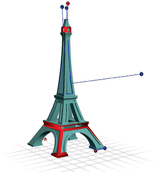
Click Import, then import your 3D model in Meshmixer, and choose the seventh icon in the bar on the left hand side: “Analysis”, which is represented by a sphere dotted with blue triangles. Finally, choose the Inspector tool in the gray box that appears.
If your file contains geometrical problems, colored spheres will appear.

Color code:
![]() A blue sphere means that there is a hole in the mesh.
A blue sphere means that there is a hole in the mesh.
![]() A red sphere points to a non-manifold area.
A red sphere points to a non-manifold area.
![]() A magenta sphere signifies that the components are disconnected from the general mesh.
A magenta sphere signifies that the components are disconnected from the general mesh.
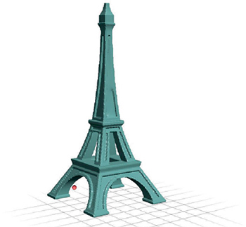
Left-click on the spheres to correct the problem. If the sphere turns gray, the repair has failed. (Command or Control-right-clicking allows you to choose the area and to repair it manually with other Meshmixer tools.) By clicking “Auto Repair All” in the task bar, all the errors will be fixed at the same time. But be careful, because the software logic may surprise you. Your model may even disappear!
If the automatic repair doesn’t work, choose each sphere one at a time to be sure that the repairs have no effect on the geometry of the object. If not, try to perform manual repairs by exploring the different tools in Meshmixer.

In the case of the Eiffel Tower, part of the top disappears completely when it is repaired automatically. In these cases where the “Inspector” fails, there is also the “Make Solid” option in the “Edit” mode (above Analysis). This feature makes your object printable, but it will drastically reduce the quality of its surfaces.
REPAIRING A FILE WITH MESHLAB
Download MeshLab:
http://meshlab.sourceforge.net
MeshLab is an open source, portable, and easy system for the processing and editing of unstructured 3D triangular meshes. The system has been developed to help the processing of the typical not-so-small unstructured models arising in 3D scanning, providing a set of tools for editing, cleaning, healing, inspecting, rendering and converting this kind of meshes.
Open MeshLab and import your broken Eiffel Tower. For this, you just have to click on “File” and “Import mesh”. Choose the Eiffel Tower.
The message “Unify Duplicated Vertices” will appears. Check the box, and click “Ok”.
To repair our object, go to the “Edit” menu and click on “Fill hole”. This will open the following window:

A list of all the hollow faces you can repair is displayed. In this case, check all the boxes, then click on “Trivial” and “Accept”. The “Trivial” function aimed at repairing even complicated faces, as we can see in the second section of our object, where some meshes are “broken” inside:
You’ll notice that the automatic repair has created some deformities on the long part of the Eiffel Tower. Models that have undergone several repairs will sometimes look rounded or pixelated. However, MeshLab will rarely refuse to repair a file, no matter how complex it may be.

Once your object has been repaired, save a new STL file with the “Export Mesh” function.
REPAIRING A FILE WITH NETFABB BASIC
Download Netfabb Basic:
When you open Netfabb Basic, don’t be surprised if a registration page asks you to wait about 10 seconds and accept the terms and conditions before giving you access to the software. This recurring invitation suggests that you upgrade to the Netfabb paid version, with many additional tools for advanced use. Click on “Later” to postpone the request for a license. The Netfabb Basic version may be used for an unlimited time.
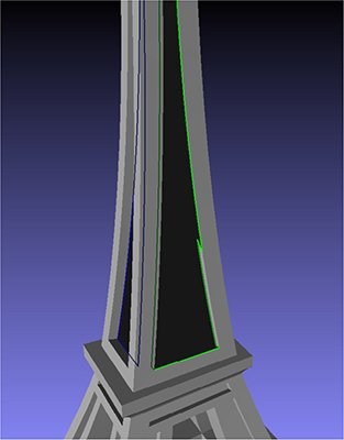
The application opens with a gradient gray background. Go to “Project,” then “Add part” to upload your 3D model. The object will be displayed in green and red. The red areas symbolize surfaces that have a problem. In the case of the Eiffel Tower, the red indicates the object’s “interior” surfaces. So that the model can be printed without any problems, all the visible surfaces must be green.

In the toolbar at the top of the application, you’ll see a little red cross called “Repair.” Choose this function.
Your object will turn blue and its mesh will be visible. A window will appear at the right with a number of options. Ignore them and select “Automatic repair,” at the very bottom. You’ll finally have the choice between “Default repair” and “Simple repair.” Both of them will work in most cases. Your surfaces are now closed and sealed. Confirm by clicking on “Apply repair” and then “Remove old part”.
To save a new STL of your piece, right-click with your mouse on the newly created piece, and then choose “Export part” and specify “as STL”.
The automatic repair of the pieces isn’t foolproof. You’ll see the same deformity on the tower where the tangent polygons were missing.

ANATOMY OF A 3D CREATION
Before exporting a file to a 3D printer, you need to know and understand the characteristics of a 3D project created layer by layer.
RAFT
This option creates a plastic base, slightly wider than that of the printed object. This base aims to give more surface adherence between the printed piece and the platform, reducing the risk of separation and buckling. The raft manually separates the piece thanks to a microtexture that weakens contact between the two pieces. When printing with soluble materials, the supports and rafts are removed chemically with Delimonene (for HIPS), water (for PVA), or a warm sodium hydroxide solution (acetal resin). It’s better to enable the “Raft” function in the following cases:

![]() Narrow, vertical piece;
Narrow, vertical piece;
![]() Multiple pieces on the same platform;
Multiple pieces on the same platform;
![]() Use of a high shrinkage plastic, like ABS;
Use of a high shrinkage plastic, like ABS;
![]() Large pieces (the corners of large pieces have a tendency to bend during printing);
Large pieces (the corners of large pieces have a tendency to bend during printing);
![]() Using the “Support” function (the support structure with very thin walls)—the raft gives the platform a solid grip surface;
Using the “Support” function (the support structure with very thin walls)—the raft gives the platform a solid grip surface;
![]() Damaged printing platform (platform surface faults will be on the bottom of the raft and not the bottom of your piece);
Damaged printing platform (platform surface faults will be on the bottom of the raft and not the bottom of your piece);
![]() In case the platform is difficult to level perfectly (the raft has thicker layers, so it is slowly crushed to become parallel to the nozzle’s movement axes). With some 3D printers, like the MakerBot mini, the absence of manual leveling on the platform makes the raft mandatory.
In case the platform is difficult to level perfectly (the raft has thicker layers, so it is slowly crushed to become parallel to the nozzle’s movement axes). With some 3D printers, like the MakerBot mini, the absence of manual leveling on the platform makes the raft mandatory.
SUPPORT (OR SCAFFOLDING)
The support is a detachable structure like the raft, which supports the parts of your objects that are likely to collapse. The support’s structure is calculated by your slicing software based on the distances between the bridges, the corners of your print’s overhangs, or even layers that float in the void above the platform. Be sure to check that no support will be generated on an inaccessible part of your object, because you’ll have to separate it by hand or with tweezers, unless you have used a soluble material (HIPS, PVA).

INFILL
The STL only contains the external walls of your objects: sometimes you will want them to be filled, and sometimes hollow for printing. Expressed as a percentage, the infill will be more or less dense depending on your needs. The higher the percentage, the denser the structure. Usually, these cells are shaped as hexagons or squares, but many other options may occur (MakerBot even has an infill setting using cat silhouettes). Note that you won’t gain much by completely filling your piece: a 20% fill is already quite rigid.

SHELL (OR WALL THICKNESS)
A 3D model’s mesh is just a mathematical surface with no thickness: to make an object real, you should give a thickness value to the wall. The “shell” in FFF is the equivalent number of passages that your nozzle will make to draw the outline of your layers. With a 0.4 mm nozzle and a 2-shell setting, your wall thickness will be 0.8 mm: the perfect compromise between speed and sturdiness. Some software, like CURA, will allow you to choose the exact thickness you want for your wall, automatically adjusting the numbers of layers needed.

LAYER HEIGHT - SURFACE CONDITION
With FFF, the objects are generated from layers ranging from 0.1 to 0.3 mm. The object’s printed surfaces may appear striated. This staircase effect increases as the surface gets closer to horizontal. So there is a texture that resembles the strata on a topographical map. Surfaces that are just slightly curved will be affected the most. The lower quality the Z resolution (for example, 0.3 mm), the more the layers will be visible. That’s why the layers are almost invisible to the naked eye with high resolution 3D printing techniques like DLP. The orientation of the model in relation to the printing surface will not only have an impact on the generation of supports and the condition of the overhang, it will also have a direct effect on the appearance of the printed strata and on the solidity of the piece.

SOLIDITY
You should observe the orientation of the piece’s grain closely when printing a functional object, and be mindful of any physical constraints. A narrow prism printed vertically will only have a fraction of the solidity of the same figure printed horizontally. By following the direction of the grain, you can also print objects that are partially flexible, despite using material that is rigid, like PLA or ABS.


EXPORTING FOR 3D PRINTING
Most 3D printers use proprietary or open source “slicing” software, but it is also possible to prepare your prints for slicing using Meshmixer.
First, import your 3D file, and then open the “Print” function.

A new interface will appear. At the top of the new menu, you can choose among a selection of 3D printers (if the 3D printer you are using is not on the list, create your own profile), and you can choose a display color for your model.

Click “Transform” to access more options. The “Fit to build volume” button will adjust your model to the maximum build volume for its current orientation so that it will be as large as possible. The “Move to platform” button is very important: it assures you that the lowest point of your object is found at the level of your 3D printer’s platform. You must always ensure that your print doesn’t “float in space” (otherwise, useless supports will be printed) or your object won’t be situated under the printing platform. Once you are satisfied, you can can click “Done”, then use “Add Supports” to create a fractal support structure that will save you time and material.


The areas to be supported will turn red, outlined in blue: you can modify these areas in the “Overhangs” toolbox, which may be accessed by clicking the tool icon to the right of the Supports button. If you aren’t satisfied with the orientation of your piece, an “Optimize Orientation” button, at the bottom, will calculate the orientation direction that requires the least support (but not necessarily best for the aesthetic quality of the piece). Once you open the “Support Generator,” it will give you access to the structure qualities: diameter of reinforcement pins on the base or on the top, etc. We recommend always having structures that are more than 2 mm in diameter, so you won’t have thin structures that may cause problems with some 3D printers.

Visualize your support by using the “Support All Overhangs” button and start over by deleting it with “Remove All Supports.” Once you are satisfied, one click on “Done” and you’ll be returned to the Meshmixer “Print” interface... This time, with a support that is ready to be exported, you can choose “Export” at the bottom of your interface, to get an STL of your piece and its support, or choose “Send To,” which will open automatically your file in the proper software for your 3D printer, if supported by Meshmixer (MakerBot, Dremel and Type A printers are on that list)


Remember: an STL file isn’t a format understood by 3D printers, but only by their software. You’ll need to go to your printer software to slice and convert your model into machine language (Gcode, X3G, Zcode...).
