
Chapter 7. Motors, Pumps, and Actuators
We started experimenting with DC motors in Chapter 4. A lot of the principles that you will learn when using DC motors are applicable to many things that you might want to control with an Arduino or Raspberry Pi.
Figure 7-1 shows a selection of DC motors. As you can see, these devices come in all sorts of shapes and sizes.

Figure 7-1. A range of DC motors
Motors are also the driving force behind lots of other useful output devices like pumps and linear actuators, both of which you will meet later in this chapter.
As you discovered in “Experiment: Controlling a Motor”, DC motors need too much current to drive them directly from the output pin of a Raspberry Pi or Arduino, but can be switched on and off using a transistor.
In this chapter, you will start by controlling the speed of a DC motor.
Controlling Speed (PWM)
In “Experiment: Mixing Colors”, you used pulse-width modulation (see “Pulse-Width Modulation” in Chapter 6) to control the brightness of an LED. You can use just the same approach to control the speed of a motor.
Experiment: Controlling the Speed of a DC Motor
This experiment uses exactly the same hardware as “Experiment: Controlling a Motor”, but instead of just turning the motor on and off, it controls the motor’s speed.
Hardware
If you have not already done so, build the hardware for “Experiment: Controlling a Motor”. As a reminder, the breadboard layout for the hardware is shown in Figure 7-3.

Figure 7-3. The breadboard layout for Experiment 2 (and Experiment 1)
Arduino Connections
Connect up the Arduino as shown in Figure 7-4. Connect GND on the breadboard to GND and the Control lead on the breadboard to pin D9 of the Arduino Uno.

Figure 7-4. Connecting the Arduino to the breadboard
Arduino Software
The Arduino sketch for this project is in the /experiments/pwm_motor_control directory, which you can find in the place where you downloaded the book’s code (see “The Book Code” in Chapter 2).
The program uses the Arduino IDE’s Serial Monitor to allow you to enter a duty cycle and then sets the motor speed accordingly:
constintcontrolPin=9;voidsetup(){//pinMode(controlPin,OUTPUT);Serial.begin(9600);Serial.println("Enter Duty Cycle (0 to 100)");}voidloop(){//if(Serial.available()){//intduty=Serial.parseInt();if(duty<0||duty>100){//Serial.println("0 to 100");}else{intpwm=duty*255/100;analogWrite(controlPin,pwm);Serial.("duty set to");Serial.println(duty);}}}

-
The
setupfunction defines thecontrolPinas being an output and also starts serial communication usingSerial.beginso that you can send values of duty cycle to the Arduino from your computer. 
-
The
loop()function checks for any waiting serial communication that has arrived over USB usingSerial.available. 
-
If there is a message, in the form of a number, the number is read from the stream of characters and converted into an
intusingparseInt. 
-
The value is checked to see if it’s in the range 0 to 100. If it’s not in this range, a reminder is sent back to your Serial Monitor over USB.
On the other hand, if the number is between 0 and 100, then that value is converted into a number between 0 and 255 and then the analogWrite() function used to set the PWM value. This is necessary, because the Arduino analogWrite function accepts a value of duty cycle between 0 and 255, where 0 is 0% and 255 is 100% duty cycle.
Arduino Experimentation
On the computer from which you programmed your Arduino, open the Serial Monitor from the Arduino IDE. To open the Serial Monitor, click the magnifying glass icon in the top right of the Arduino IDE. This is circled in Figure 7-5.
This will then prompt you to enter a value of duty cycle between 0 and 100. Experiment by entering different values to see how this affects the speed of the motor.
Notice that when you get down to say 10 or 20, the motor may not actually turn, but instead make a rather strained kind of whine as there is not quite enough power arriving at the motor to overcome friction and get it moving.
If you intend to use the motor for something practical, this sketch is a great way of working out the useful minimum value of duty cycle for the motor.
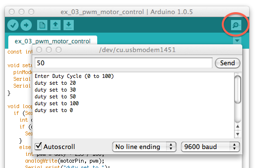
Figure 7-5. Using the Serial Monitor to control the motor speed
When you want to stop the motor, just set the duty to 0.
Raspberry Pi Connections
Connect the breadboard to your Raspberry Pi, as shown in Figure 7-6. Using female-to-male jumper wires, connect GND of the breadboard to one of the GND pins of the GPIO connector and the control wire of the breadboard to pin 18 of the Raspberry Pi.

Figure 7-6. Connecting the Motor Control breadboard to a Raspberry Pi
Raspberry Pi Software
The Raspberry Pi software follows a very similar pattern to the Arduino code. In this case, the program will prompt you for a value of duty cycle and control pin 18 accordingly.
You will find the code for the following program in the pwm_motor_control.py file, which is in the python/experiments directory (you’ll find this in the place where you downloaded the book’s code—see “The Book Code” in Chapter 3):
importRPi.GPIOasGPIOimporttimeGPIO.setmode(GPIO.BCM)control_pin=18#GPIO.setup(control_pin,GPIO.OUT)motor_pwm=GPIO.PWM(control_pin,500)#motor_pwm.start(0)#try:whileTrue:#duty=input('Enter Duty Cycle (0 to 100):')ifduty<0orduty>100:('0 to 100')else:motor_pwm.ChangeDutyCycle(duty)finally:("Cleaning up")GPIO.cleanup()
-
The first part of the program is the same as the code for “Experiment: Controlling a Motor”, but after defining pin 18 to be an output.
-
This line sets up that pin to be a PWM output. With the RPi.GPIO library, you can set any of the GPIO pins to be PWM outputs. The parameter
500sets the PWM frequency to 500Hz (pulses per second). -
The PWM output does not actually start until
startis called. Its parameter is the initial duty cycle and because we want the motor to be off initially, this is set to0. -
Inside the main loop, the value of
dutyis requested from you usinginputand then it’s range checked. If its between 0 and 100, it is used to set the duty cycle using the functionChangeDutyCycle.
Raspberry Pi Experimentation
Run the program as superuser using sudo and then try entering different values of duty cycle. The motor speed should change just as it did with the Arduino:
pi@raspberrypi ~/make_action/python $ sudo python pwm_motor_control.py
Enter Duty Cycle (0 to 100): 50
Enter Duty Cycle (0 to 100): 10
Enter Duty Cycle (0 to 100): 100
Enter Duty Cycle (0 to 100): 0
Enter Duty Cycle (0 to 100):
Controlling DC Motors with a Relay
If you only need your Arduino or Raspberry Pi to occasionally turn a motor on and off, then one approach is to use a relay. Although this is often considered a rather old-fashioned way of doing things, it has a number of advantages:
- It’s easy to do, requiring few components.
- Extremely good isolation between the electrically noisy, high-current motor and the delicate Pi or Arduino.
- High-current handling (with the right relay).
- You can use ready-made relay modules directly with a Raspberry Pi or Arduino.
The downsides to using a relay or a relay module include the following:
- They are relatively large components.
- They can only switch the motor on and off—they cannot control the speed.
- They are electromechanical devices and typically are expected to survive perhaps 10,000,000 switching operations before something in them breaks.

Figure 7-7. Relays
Although you are using a relay to control a motor in this chapter, the relay does just act as a switch, so you can use it to control pretty much anything.
Relays like this are called Single Pole Change Over (SPCO), because rather than have just two terminals that are either connected or not, they actually have three. They have what is called a common terminal, usually labeled COM, and two other terminals: normally open (NO) and normally closed (NC). In this context, normally means without power applied to the relay coil. So, the NO and COM connections will be “open” (not connected) until the coil is energized. The NC contact will behave in the opposite manner, so the NC and COM terminals will “normally” be connected, but will disconnect when the coil is energized.
Generally speaking, just the NO and COM terminals of the relay are used for switching.
Switching a Relay with Arduino or Raspberry Pi
When using a relay with a Raspberry Pi or Arduino, use one that has a 5V coil voltage. Relays coils take too much current (about 50mA) to drive directly from either a Raspberry Pi or an Arduino, and so, in both cases, we will use a small transistor to switch the relay coil to 5V.
Figure 7-8 shows the schematic diagram for switching a relay.

Figure 7-8. Using a small transistor to switch a relay
The coil of a relay designed to work at 5V will draw about 50mA of current. This is slightly too much for an Arduino and much too much for a Raspberry Pi GPIO pin. So, just as in “Experiment: Controlling a Motor”, you will use a transistor to control the motor (in this case, the relay coil will replace the motor as the “load.”
This arrangement only makes sense if the motor (or whatever other load you want to control) is of sufficiently high current consumption that it could not be controlled directly using the transistor.
Like a motor, the coil of a relay is capable of producing voltage spikes when it is switched on and off, and so this schematic also needs a diode.
It is very apparent from Figure 7-8 that the switch part of the relay is completely isolated electrically from the coil part. This means that there is less chance of any electrical noise, voltage spikes, or general bad electrical behavior finding its way back to your Arduino and Raspberry Pi.
Because the relay only requires about 50mA when it’s powered up, a lowly 2N3904 transistor costing a few cents will work just fine.
Relay Modules
If you have a few things that you want to control and they are compatible with the limitations of relays that I described earlier (on/off control only), a great shortcut is to buy a relay module such as the one shown in Figure 7-9.

Figure 7-9. An 8-channel relay module
These modules are available on eBay and Amazon at very low cost and include both the relay and transistors to drive them, as well as little LEDs that actually tell you when a particular relay has been activated. This means that you can connect them directly to a Raspberry Pi or Arduino.
They are available for controlling a single relay through to controlling even more than the eight that this module has.
The modules will normally have the following pins:
GND (Ground)
VCC or 5V Connect this to 5V on the Raspberry Pi or Arduino. This supplies power to the relay coils when activated.
Data pins Each data pin controls one of the relays. Sometimes these pins will be “active high,” meaning you have to set the GPIO pin to which they are connected to high to turn them on and sometimes they are “active low” and the relay coil will be activated when the pin is low.
The module will also have a row of screw terminals that are connected straight to the relay contacts.
Experiment: Controlling a DC Motor with a Relay Module
In this experiment, you will just turn a motor on and off using a relay.
This project uses a ready-made relay module. This module only needs one relay. The relay module I used actually has eight relays, so if you prefer you could use a module with fewer relays on it.
Parts List
Whether you are using a Raspberry Pi or Arduino (or both), you are going to need the following parts to carry out this experiment:
| Part | Sources |
| Small 6V DC motor |
Adafruit: 711 |
| Relay module | eBay |
| 6V (4 x AA) battery box | Adafruit: 830 |
| Jumper wires to suit the relay module |
See Appendix A |
Some relay modules have sockets and some plugs to connect to your Arduino or Raspberry Pi, so select jumper wires to suit. That is, to connect a relay module with male pins to an Arduino, you will need female-to male-jumper wires (Adafruit: 826). To connect it to a Raspberry Pi, you will need female-to-female jumper wires (Adafruit: 266).
Wiring
The wiring diagram for this experiment is shown in Figure 7-10.

Figure 7-10. Wiring diagram for controlling a DC motor with a relay module
The relay contacts act like a switch that can be in one of two positions. There are common, normally open, and normally closed terminals. When the relay coil is not energized, the common terminal is connected to the normally closed terminal. When power is applied to the coil, the switch flips over and the common terminal is now connected to the normally open contact.
The software for both Arduino and Raspberry Pi is almost identical to that of “Experiment: Controlling a Motor”. The only difference will be if your relay module has active low logic like the one I used.
Arduino Software
The Arduino sketch is in the arduino/experiments/relay_motor_control directory (you’ll find this in the place where you downloaded the book’s code—see “The Book Code” in Chapter 2).
The program will turn the relay (and hence the motor) on for 5 seconds, then off for 2 seconds and then repeat. The full code is shown here:
constintcontrolPin=9;voidsetup(){pinMode(controlPin,OUTPUT);}voidloop(){digitalWrite(controlPin,LOW);//delay(5000);digitalWrite(controlPin,HIGH);delay(2000);}
-
This code is just the same as for “Experiment: Controlling an LED”, except that
LOWandHIGHare swapped over on thedigitalWritefunctions. If you find that when you run the program the motor turns on for 2 seconds and off for 5, rather than the other way around, this means that the logic for your relay module is active high and you should swapLOWandHIGHback to how they were in “Experiment: Controlling an LED”.
Raspberry Pi Software
You will find code for the following program in the relay_motor_control.py file, which is in the python/experiments directory (you’ll find this in the place where you downloaded the book’s code):
importRPi.GPIOasGPIOimporttimeGPIO.setmode(GPIO.BCM)control_pin=18GPIO.setup(control_pin,GPIO.OUT)try:whileTrue:GPIO.output(control_pin,False)time.sleep(5)GPIO.output(control_pin,True)time.sleep(2)finally:("Cleaning up")GPIO.cleanup()
Choosing a Motor
DC motors come in all sorts of shapes and sizes, and it is important to get one that is powerful enough for your project. The two main things that you need to know about a motor are how much turning force the motor can produce (torque) and how fast the motor spins.
If it spins faster than you need but does not have enough torque, you can trade one off against the other using a gearbox.
Torque
Put crudely, torque is the turning power of a motor. The higher a motor’s torque, the stronger its turning force.
Scientifically speaking, torque is defined as a force multiplied by a distance, where the force is measured in newtons (N) and the distance in meters (m). In more practical terms, the force component of torque is often expressed as the force needed to lift a certain weight in kilograms or ounces with a distance measured in centimeters or inches.
Distance comes into the equation because the further away from the motor’s rotor, the less force the motor will be able to exert. For example, if a motor is specified as having a torque of 15oz.in (ounces x inches), then 1in from the rotor’s center it will be able to hold a weight of 15oz—that is, the motor will not be able to lift the weight higher, but at the same time, the weight won’t fall. However, at 10in from the rotor, it will only be able to hold a weight of 1.5oz (10in x 1.5oz = 15oz.in).
Figure 7-11 shows the relationship between weight and distance from the motor’s axis.

Figure 7-11. Torque in a nutshell
RPM
DC motors spin pretty fast, which is why they are often used with gears or as gearmotors (see the following two sections). A typical low-voltage DC motor might spin at 10,000 rpm (revolutions per minute). This means that the motor shaft turns some 166 times per second.
Although you can control the speed of the motor using PWM, this also reduces the energy of the motor, so the torque that the motor generates will remain low.
Gears
Gears allow you to produce a slower rotation with the side effect of increasing torque. If you use a 5:1 gearbox (Figure 7-12) with 50 teeth on one cog and 10 on the other, then for each five turns of the motor, there will be just one turn from the output of the gearbox, but the torque available at the output of the gearbox will be 10 times that available directly from the motor.

Figure 7-12. Gears
Gearmotors
Because motors are so often used with gears, for many applications, it is better to buy a gearmotor, which combines a motor with a gearbox into a single package.
For examples of a wide range of gearmotors, take a look at Polulu.
You can buy some extremely cheap gearmotors that use plastic cogs. These work but will not last as long or provide as much torque as a gearmotor with metal gears.
Pumps
Pumps are usually a DC motor, or sometimes a brushless DC motor (these will be discussed in “Brushless DC Motors”) that drives a mechanism that moves liquid from one place to another.
Two common types of pump that are often used by hobbyists are the peristaltic pump and the velocity pump. These are shown side by side in Figure 7-13. The peristaltic pump is on the left.

Figure 7-13. A peristaltic pump (left) and velocity pump (right)
Both of these pumps are powered by a DC motor, but they have quite different properties. If you want slow and measured, use a peristaltic pump; if you want fast and furious, use a velocity pump.
Peristaltic Pumps
Peristaltic pumps are designed to move liquid in a very measured way. In fact, they are often used in medical and research applications to move a fairly precise quantity of liquid. For more accurate control of flow, peristaltic motors are sometime driven by stepper motors (see Chapter 10).
Figure 7-14 shows how a peristaltic pump works.
The pump uses a gear motor driving rollers that squeeze flexible tubing, pushing the fluid through the tubing. It’s not surprising that given the constant squeezing, the tube will eventually give out and need replacing. The pumps are usually designed to allow the tubing to be swapped out.

Figure 7-14. How a peristaltic pump works
If you drive a peristaltic pump’s gearmotor with PWM and an H-bridge (we’ll discuss H-bridges in Chapter 8), you can control both the flow rate and direction of flow of the liquid.
A peristaltic pump will self-prime—that is, if the pump is a little higher up than the source of water, it will create enough suction to pull the water into the pump and start pumping it.
Velocity Pumps
If you are more concerned with shifting a lot of liquid quickly, then you need a velocity pump. There are various designs of velocity pump, but the most common is probably the radial pump (Figure 7-15).

Figure 7-15. How a radial velocity pump works
Liquid enters the pump from the front of Figure 7-15 on the axis of the motor which drives impellers. These impellers impart centrifugal force to the liquid that flies out to the edge of the pump housing and out of the outlet.
Velocity pumps are not self-priming, and need to already have water at the inlet before they will pump. Unlike peristaltic pumps, they also allow water to flow through them, even when not pumping. Some of these pumps are intended for garden pond or aquarium use and can be completely submerged in water.
Unlike the peristaltic pump, this type of pump cannot be reversed. Some pumps of this design use a brushless DC motor with its own control electronics all in one enclosure to provide maximum pumping power for a small size.
Project: Arduino House Plant Waterer
This simple Arduino project (Figure 7-16) uses a peristaltic pump to deliver a measured amount of water to your house plants every day (which is very useful while you are away on vacation).

Figure 7-16. A house plant waterer
The project does not use a timer to decide when to water the plant; instead it measures the light intensity so that the plant is watered whenever it goes dark.
Design
Figure 7-17 shows the schematic diagram for the project.
An MPSA14 transistor is used by the Arduino to turn the pump’s motor on and off. The diode D1 offers protection against negative voltage spikes.
On the left of the schematic, you can see a photoresistor and fixed-value resistor form a voltage divider to measure the light intensity on analog pin A0 of the Arduino.

Figure 7-17. Schematic diagram for the house plant waterer
The more light there is falling on the photoresistor, the lower its resistance, pulling the voltage on A0 up toward 5V.
This is a pretty easy project to build. Your pump is unlikely to have leads attached, so the only soldering that you may need to do for this project is to attach some leads to the pump motor.
Parts List
You will need the following parts to build this project:
| Name | Part | Sources |
| Arduino Uno | ||
| Q1 | MPSA14 Darlington transistor | Mouser: 833-MPSA14-AP |
| R1, R3 | 1kΩ resistor | Mouser: 291-1k-RC |
| R2 | Photoresistor (1kΩ) |
Adafruit: 161 Sparkfun: SEN-09088 |
| D1 | 1N4001 diode |
Adafruit: 755 Sparkfun: COM-08589 Mouser: 512-1N4001 |
| 12V peristaltic pump | eBay | |
| 400-point solderless breadboard | Adafruit: 64 | |
| Male-to-male jumper wires |
Adafruit: 758 |
|
| Tubing to fit the pump 3 ft | Hardware store | |
| 12V 1A power supply | Adafruit: 798 | |
| Large water container | ||
| Hookup wires to solder to the pump motor | Adafruit: 1311 |
The type of peristaltic pump used in this project is intended for use in an aquarium, and is available at very low cost.
The tubing that I used in the project came as part of a “watering” kit from a hardware store. It came complete with small plastic joining pieces intended to join one length of the piping they supplied to another. These were perfect for attaching the tube from the pump to the extra lengths of tube. The tubes need to be airtight, or the pump will not work.
Construction
Constructing this project requires a bit of simple work with the breadboard and some possible handiwork to adapt the water container.
Step 2: Construct the breadboard
Use the breadboard layout of Figure 7-18 as a reference while you are fitting the components onto the breadboard.

Figure 7-18. The breadboard layout for the house plant watering project
Make sure that the transistor and diode are the right way around.
Step 3: Fix tubing onto the pump
You need two lengths of tubing. One about the length of the water container that will reach from the pump inlet, positioned at the top of the container down into the water. The second length needs to reach from the outlet of the pump to the plant that you want to water. Figure 7-19 show a close-up of the pump and the tubes.
The inlet and outlet of the pump are not usually marked, but peristaltic pumps are reversable, so if you find that it’s sucking when it should be blowing, it may be easier to swap over the leads to the motor rather than swap over the pipes.

Figure 7-19. Connecting tubes to the pump
Step 4: Final assembly
I found it convenient to fit the pump onto the top of the water container with the head of the pump pushed into the top of the container and the motor end sticking up. The inlet tube goes straight down into the container and the outlet tube comes out to the side and off to the plant. To get the pump to fit I had to cut a little of the neck off the milk container that I used.
Figure 7-16 shows the arrangement I used for the project, but if you prefer, you could site the pump low down near the breadboard, but you will need a longer tube.
Software
The sketch for this project is arduino/projects/waterer/pr_01_waterer.ino, which you’ll find in the place where you downloaded the book’s code (you will also find a second sketch in the projects/ folder called waterer_test, which is used to calibrate the light sensor):
constintmotorPin=9;constintlightPin=A0;constlongonTime=60*1000;// 60 secondsconstintdayThreshold=200;constintnightThreshold=70;booleanisDay=true;voidsetup(){pinMode(motorPin,OUTPUT);}voidloop(){intlightReading=analogRead(lightPin);if(isDay&&lightReading<nightThreshold){// it went darkpump();isDay=false;}if(!isDay&&lightReading>dayThreshold){isDay=true;}}voidpump(){digitalWrite(motorPin,HIGH);delay(onTime);digitalWrite(motorPin,LOW);}
-
The sketch starts by defining constants for the two Arduino pins that are used: the motor control pin and the analog input (
lightPin) that uses the photoresistor to measure the light intensity. -
The constant
onTimespecifies how long the pump should stay on each night. While you are testing the project, you might want to set this to a short period, perhaps 10 seconds to prevent too much waiting around.The most interesting part of this sketch is the part that detects nightfall. Because the Arduino does not have a built-in clock, it does not know the time unless you add real time clock (RTC) hardware to it. For the purposes of this project, we want the plant to be watered once a day, so nightfall will be an appropriate trigger for the watering to start. Having watered the plant, you don’t then want watering to be triggered until the next night, so an intervening period of brightness (otherwise known as day) is needed.
-
To help distinguish between night and day, two constants are defined:
dayThresholdandnightThreshold. You will probably need to change these values to suit the location of your plant and the sensitivity of your photoresistor. The basic idea is that if the current light reading is greater thandayThresholdit’s daytime and if it’s less thannightThreshold, then it’s nighttime. You might be wondering why there are two constants rather than just one. The answer is that at dusk, when it just starts to go dark, the light level might increase above and below the threshold for a while, causing multiple triggerings. -
The Boolean variable
isDayholds the current state of daytime-ness. IfisDayistrue, then as far as the plant waterer is concerned, it’s daytime. 
-
The logic to decide if a watering is due is in the
loopfunction. This first takes a light reading. 
-
If it is currently daytime but the light reading is below
nightThresholdthen it’s just gone dark and so the function pump is called to do some watering. The variableisDayis then set tofalseto indicate that it’s nighttime and prevent further watering for now. 
-
The second
ifstatement inloopchecks that it’s nighttime (!isDay) and that the light level is now abovedayThreshold. If both these conditions are true, thenisDayis set to betrue. 
-
Finally, the
pumpfunction has the job of turning on the pump, waiting for the period specified inonTimeand then turning the pump off again.
Using the Project
Before running the project proper, the test program waterer_test.ino should be uploaded to the Arduino, so that you can find suitable values for dayThreshold and nightThreshold. So upload this sketch to the Arduino and open the Serial Monitor.
A series of readings should appear, one every half second in the Serial Monitor. These correspond to the current light reading. Make a note of the reading during daylight, when it’s fairly overcast. Use about half this value for dayThreshold, to allow for really dull days.
Next, wait until it goes as dark as it’s going to get at the plant’s location and take another reading. You may prefer to just guess, or put your finger over the light sensor. Use twice this reading for nightThreshold. Remember that you do need nightThreshold to be significantly less than dayThreshold. So you may need to make compromises in your estimates for these two values.
Now you can alter dayThreshold and nightThreshold in the real sketch (pr_01_waterer.ino) and then upload it to the Arduino.
You can simulate darkness falling by putting your finger over the photoresistor. This should start the pump running for the period specified.
The pump I used pumped about 90mL/minute. To decide on a watering time, you can use a measuring jug and stopwatch to find your pump’s volumetric flow rate and adjust onTime to deliver the amount of water your plant needs.
Linear Actuators
Linear actuators convert the rotation of a DC motor into a linear movement. They are often used to open and close doors or windows.
They use a threaded drive shaft with what’s effectively a nut on it that is constrained from turning, but is free to move up and down the threaded shaft, pushing the end of the actuator in and out. Figure 7-20 illustrates how this works, and Figure 7-21 shows a typical linear actuator.

Figure 7-20. How a linear actuator works

Figure 7-21. A linear actuator
Linear actuators move the shaft quite slowly as the long threaded shaft and nut combination effectively acts as a reduction gearbox, and in any case there is usually a normal gearbox on the end of the motor as well. This low speed and the usually quite powerful DC motors attached mean that they can provide quite a strong pushing or pulling force. The one shown in Figure 7-21 has a pushing or pulling force of 1500N (newtons). This is enough to lift 330lbs or 150kg. At full load, the motor on a linear actuator like this can easily draw 5A at 12V.
You would generally drive the motor for a linear actuator with an H-bridge (at least 5A maximum current) to allow it to move in both directions. To prevent the linear actuator damaging itself when it gets to either end of its travel, the devices usually incorporate limit switches that cut off the power automatically when the shaft reaches an end stop. This simplifies driving the motor, because you can just instruct the H-bridge to power the motor in one direction or the other for a fixed time period that is long enough for the actuator to extend or retract fully.
In “Project: Arduino Beverage Can Crusher”, a linear actuator like the one in Figure 7-21 is used to make a beverage can crusher.
Solenoids
Solenoids are used for door latches and valves. Like linear actuators, they have a linear motion, but they are much simpler devices. They are effectively electromagnets that make an armature move in and out. The range of travel is very short, usually a fraction of an inch. Figure 7-22 illustrates how a solenoid works, and Figure 7-23 shows a 12V valve that uses a solenoid.

Figure 7-22. How a solenoid works

Figure 7-23. A 12V water control valve
When the coil is energized, it pulls the plunger into the coil against the force of the spring. When the power is removed from the coil, the plunger is free to move back to its initial position.
The water valve shown in Figure 7-23 is designed to switch a pressurized household water supply. When no power is supplied to the valve, no water flows, but when the coil is energized, a plunger retracts, allowing water to flow through the valve for as long as power is applied to the valve.
The unit shown is a 12V unit, and is the kind of thing that you might find in a domestic washing machine. You also often encounter 120V or 220V AC versions of these valves for use in domestic appliances. Having high voltages near water is fraught with danger, so I strongly recommend sticking to 12V pumps and valves for your own projects.
You will also find door latches that are controlled by a solenoid.
Summary
In this chapter, you have learned about how DC motors work, as well as how to switch a motor on and off using an Arduino or Raspberry Pi. You also learned about controlling the speed of a motor.
The next chapter will show you how to use a circuit called an H-bridge to control the direction in which the motor turns.