TRANSFORMERS
Block Diagram
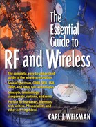
Figure 4-20. Block diagram of a transformer.

The Transformer's Function
If you recall the discussion about match, there is a standard "size" of inputs and outputs for all RF components which is 50 Ω (ohm) impedance. When the output of one device and the input of the next device are both 50 Ω (or nearly so), then the two devices are connected directly and the slight mismatch (leaking) is tolerated. However, sometimes one of the devices has an input or output which is so far from 50 Ω that trying to connect it to another device with the proper input (50 Ω) causes a horrible mismatch (leaking). What is needed in this situation is a matching circuit, and so in steps the transformer. It "transforms" the wrong impedance (maybe 100 Ω) into the right impedance (50 Ω), and that way the device with the wrong impedance can be utilized. A transformer is the actual device represented by the impedance matching circuit graphically depicted in Figure 2-6 on page 30. A block diagram of a transformer is shown in Figure 4-20.
Recall the garden hose analogy and imagine trying to connect two garden hoses with different size openings. A transformer is needed between the two hoses to adapt the hose with the bigger opening to that of the hose with the smaller opening, which is exactly the function of an RF transformer. Two small surface-mount transformers are shown in Figure 4-21. If you look closely, you can see the wires wrapped around like a coil, which is what the squiggly lines represent in Figure 4-20.
Did You Know?
In the world of RF, the prefix trans is used so frequently that RF engineers abbreviate it with the letter "X." Therefore, the word transformer is abbreviated as xformer, transmitter is abbreviated as xmitter, and so on. Now you can xlate from RF to English.
Impedance Ratio
As you might imagine, there are a lot of "wrong" impedances out there and so there are many different transformers. The key performance parameter of a transformer is its impedance ratio. The impedance ratio dictates what "wrong" impedance the transformer will make "right." If the impedance ratio is specified as 2:1, then the transformer will "transform" 100 Ω into 50 Ω. Therefore, a 2:1 transformer is used when the "wrong" impedance is 100 Ω.
There are some other uses for transformers, but they depend more on the subtleties of electronics, and for the sake of this book it is easiest to ignore them. Transformers are most often used to "transform" impedances, which is the best way to think of them.
Figure 4-21. Surface-mount transformers. Courtesy of Coilcraft, Inc.
