COUPLERS
Block Diagram
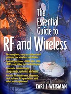
Figure 4-13. Block diagram of a directional coupler.

How Couplers Work
To understand how couplers function, I will use the analogy of wine tasting. Before you buy an expensive bottle of wine, you want to taste a sample. The sample does not have to be very big to know whether you are going to enjoy the whole bottle. This is how couplers work; only instead of sampling wine, they sample the RF signal.
Visually, a signal enters the coupler at point A (see Figure 4-13) and generally makes its way to point C and along its merry way somewhere else in the system. Except, as it goes from A to C, a tiny fraction of the signal is siphoned off and brought out at point B, called the sample port. The signal at point B is the sample. What can be done with the sample? Lots.
Imagine RF signals having color. Suppose the goal is to transmit an orange signal out of the antenna. A coupler could be placed just before the antenna to sample the signal before it gets radiated out. As long as the sample is orange, everything would be fine. But what if the signal which the coupler samples turns red? At that point, the sample could be used to tell some other part of the circuit to crank up the yellow, which is exactly the purpose of a coupler. A coupler samples an RF signal and yells back to some other component to change something if everything isn't just right. And if you have been paying attention, you will recognize this as an explanation of feedback. Couplers are often used as part of feedback circuits in RF systems. A directional coupler is shown in Figure 4-14. Couplers are passive devices.
Figure 4-14. A directional coupler. Courtesy of TRM, Inc.

Types of Couplers
Directional and Bidirectional Couplers
The coupler discussed above is referred to as a directional coupler, which means that it has one sample port and only works in one direction. A cousin to the directional coupler is the bi-directional coupler. The bi-directional coupler works in both directions and has two sample ports. (Because of the quirky nature of RF, separate sample ports are needed for waves traveling in opposite directions.)
Another way to think of directional couplers is as two-way dividers in which the power is divided unevenly: 99% of the power goes to the output and 1% goes to the sample port.
The key performance parameter for a directional coupler, in addition to insertion loss, is coupling accuracy. The amount of signal which comes out of the sample port must be known exactly and must not vary (too much) over frequency, time, temperature, or anything else, for the coupler to function properly.
Quadrature Couplers
Just when you thought you had mastered the subject of couplers, RF engineers came along and invented a whole new breed of coupler called the quadrature or Lange coupler, also referred to as a quadrature hybrid or quad hybrid. Unlike directional couplers with their sample port, quadrature couplers are almost identical to two-way power dividers. Their output power is divided evenly between the two outputs. The block diagram for a Lange coupler is shown in Figure 4-15.
Figure 4-15. Block diagram of a Lange coupler.

There must be some difference between a quadrature coupler and a two-way power divider, right? There is, and the difference between the two concerns subtleties of RF which are way beyond the scope of this book; but as you know, that won't keep me from trying to explain it. The difference between a two-way power divider and a quadrature coupler is that in a quadrature coupler the two outputs are "out of phase." Whoa! I'm not even going to begin to explain what that means, but do you recall the balanced amplifier of a few chapters back? In a balanced amplifier, the input signal is divided in two, sent through two parallel amplifiers, and then combined again at the output. Well, that divider and combiner are, in reality, quadrature couplers. To simplify matters, quadrature couplers are used in balanced amplifiers because they improve the amplifier's match (remember match?). They are also used in digital modulation, which you will learn about in a future chapter. And just as a point of information, with reference to Figure 4-15, the isolated port does not necessarily do anything; it's just there for confusion.