
Chapter 16 Materials for optical devices
- 16.1 Introduction and synopsis 366
- 16.2 The interaction of materials and radiation 366
- 16.3 Charts for optical properties 371
- 16.4 Drilling down: the physics and manipulation of optical properties 372
- 16.5 Optical design 380
- 16.6 Summary and conclusions 381
- 16.7 Further reading 381
- 16.8 Exercises 381
- 16.9 Exploring design with CES 382
- 16.10 Exploring the science with CES Elements 383
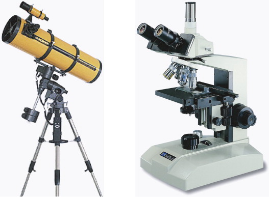
Instruments using the ability of materials to reflect and refract.
(Image of microscope courtesy of A–Z Microscope Corporation, California, USA)
16.1 Introduction and synopsis
It was at one time thought that the fact that light could travel through space—from the sun to earth, for instance—must mean that space was not really empty but filled with ‘luminiferous ether’. It was not until the experiments of Michelson1 and Morley in 1881 that it was realised that light did not need a ‘material’ for its propagation but could propagate through totally empty space at what is now seen as the ultimate velocity: 3 × 10⁸ m/s.
When radiation strikes materials, things can happen. Materials interact with radiation by reflecting it, absorbing it, transmitting it and refracting it. This chapter is about these interactions, the materials that do them best and the ways we use them. The chapter opening page shows two: a reflecting telescope and a refracting microscope, each of which depend on the optical properties of materials.
16.2 The interaction of materials and radiation
Electromagnetic (e-m) radiation permeates the entire universe. Observe the sky with your eye and you see the visible spectrum, the range of wavelengths we call ‘light’ (0.40–0.77 µm). Observe it with a detector of X-rays or γ-rays and you see radiation with far shorter wavelengths (as short as 10−4 nm, one-thousandth the size of an atom). Observe it instead with a radio-telescope and you pick up radiation with wavelengths measured in millimeters, meters or even kilometers, known as radio and microwaves. The range of wavelengths of radiation is vast, spanning 18 orders of magnitude (Figure 16.1). The visible part of this spectrum is only a tiny part of it—but even that has entrancing variety, giving us colours ranging from deep purple through blue, green and yellow to deep red.
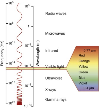
Figure 16.1 The spectrum of electromagnetic (e-m) waves. The visible spectrum lies between the wavelengths 0.4 and 0.77 µm.
The intensity I of an e-m wave, proportional to the square of its amplitude, is a measure of the energy it carries. When radiation with intensity Io strikes a material, a part IR of it is reflected, a part IA absorbed and a part IT may be transmitted. Conservation of energy requires that
The first term is called the reflectivity of the material, the second the absorptivity and the last the transmittability (all dimensionless). Each depends on the wavelength of the radiation, on the nature of the material and on the state of its surfaces. They can be thought of as properties of the material in a given state of surface polish, smoothness or roughness.
In optics we are concerned with wavelengths in the visible spectrum. Materials that reflect or absorb all visible light, transmitting none, are called opaque, even though they may transmit in the near visible (infrared or ultraviolet). Those that transmit a little diffuse light are called translucent. Those that transmit light sufficiently well that you can see through them are called transparent; a subset of these that transmit almost perfectly, making them suitable for lenses, light-guides and optical fibres, are given the additional title of optical quality. Metals are opaque. To be transparent a material must be a dielectric.
Specular and diffuse reflection
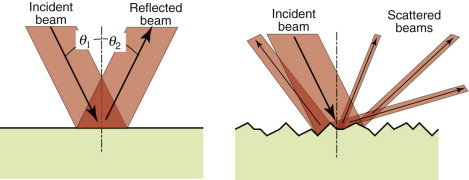
Metals reflect almost all the light that strikes them; none is transmitted and little is absorbed. When light strikes a reflecting surface at an incident angle θ1, part of it is reflected, leaving the surface with an angle of reflection θ2 such that
Specular surfaces are microscopically smooth and flat. A beam striking such a surface suffers specular reflection, meaning that it is reflected as a beam, as on the left of Figure 16.2. Diffuse surfaces are irregular; the law of reflection (equation (16.2)) still holds locally but the incident beam is reflected in many different directions because of the irregularities, as on the right of the figure.
Absorption
If radiation can penetrate a material, some is absorbed. The greater the thickness x through which the radiation passes, the greater the absorption. The intensity I, starting with the initial value I0, decreases such that
where β is the absorption coefficient, with dimensions of m−1 (or, more conveniently, mm−1). The absorption coefficient depends on wavelength, with the result that white light passing through a material may emerge with a color corresponding to the wavelength that is least absorbed—that is why a thick slab of ice looks blue.
Example 16.1
Water has an absorption coefficient for blue light of β = 0.01/m and for red light or β = 0.3/m. How much are the red and blue components of white light absorbed when a beam of white light passes through 10 metres of water? What is the consequent color of the light perceived by an observer 10 metres from the source?
Answer. The transmitted fraction of the blue component![]() ; thus 10% is absorbed. The transmitted fraction of the red component is
; thus 10% is absorbed. The transmitted fraction of the red component is ![]() ; thus 95% is absorbed. The water, in consequence, appears blue.
; thus 95% is absorbed. The water, in consequence, appears blue.
Transmission
By the time a beam of light has passed completely through a slab of material it has lost some intensity through reflection at the surface at which it entered, some in reflection at the surface at which it leaves and some by absorption in between. Its intensity is
The term (1 − IR/Io) occurs to the second power because intensity is lost through reflection at both surfaces.
Refraction
The velocity of light in a vacuum, co = 3 × 10⁸ m/s, is as fast as it ever goes. When it (or any other electromagnetic radiation) enters a material, it slows down. The index of refraction, n, is the ratio of its velocity in a vacuum, co, to that in the material, c:

This retardation makes a beam of light bend or refract when it enters a material of different refractive index. When a beam passes from a material 1 of refractive index n1 into a material 2 of index n2 with an angle of incidence θ1, it deflects to an angle θ2, such that
as in Figure 16.3(a); the equation is known as Snell’s law2. The refractive index depends on wavelength, so each of the colours that make up white light is diffracted through a slightly different angle, producing a spectrum when light passes through a prism. When material 1 is vacuum or air, for which n1 = 1, the equation reduces to
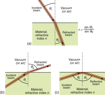
Equation (16.6) says that light passes from a material with index n1 = n into air with n2 = 1, it is bent away from the normal to the surface, like that in Figure 16.3(b). If the incident angle, here θ1, is slowly increased, the emerging beam tips down until it becomes parallel with the surface when θ2 = 90 degrees and sin θ2 = 1. This occurs at an incident angle, from equation (16.6), of

For values of θ1 greater than this, the equation predicts values of sin θ2 that are greater than 1, and that can’t be. Something strange has to happen, and it does: the ray is totally reflected back into the material, as in Figure 16.3(c). This total internal reflection has many uses, one being to bend the path of light in prismatic binoculars and reflex cameras. Another is to trap light within an optical fibre, an application that has changed the way we communicate.
Reflection is related to refraction. When light traveling in a material of refractive index n1 is incident normal to the surface of a second material with a refractive index n2, the reflectivity is
If the incident beam is in air, with refractive index 1, this becomes
Thus, materials with high refractive index have high reflectivity.
Example 16.2
A material has a refractive index of n = 1.3. At what internal incident angle is a beam of light first totally reflected?
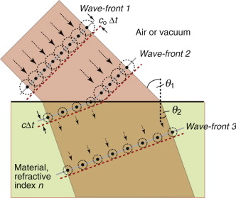
Before leaving Snell and his law, ponder for a moment on the odd fact that the beam is bent at all. Light entering a dielectric, as we have said, slows down. If that is so why does it not continue in a straight line, just more slowly? Why should it bend? To understand this we need Fresnel’s3 construction. We think of light as advancing via a series of wave-fronts. Every point on a wave-front acts as a source, so that, in a time Δt the front advances by cΔt, where c is the velocity of light in the medium through which it is passing (c = co in vacuum or air)—as shown in Figure 16.4 with Wave-front 1 advancing coΔt. When the wave enters a medium of higher refractive index it slows down so that the advance of the wave-front within the medium is less than that outside, as shown with Wave-front 2 advancing cΔt in the figure. If the angle of incidence θ1 is not zero, the wave-front enters the second medium progressively, causing it to bend, so that when it is fully in the material it is traveling in a new direction, characterised by the angle of refraction, θ2. Simple geometry then gives equation (16.6).
16.3 Charts for optical properties
Refractive index and dielectric constant
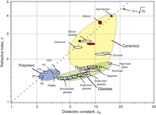
Figure 16.5 shows the refractive index, n, of dielectrics, plotted against the dielectric constant εR (defined in Chapter 14). Those shown as white bubbles are transparent to visible light; those with red bubbles are not, but transmit radiation of longer wavelengths (germanium, for instance, is used for lenses for infrared imaging). Note the wide and continuous range of refractive index of glasses, determined by their chemistry. This ability to control n by manipulating composition is central to the selection of materials for lenses and optical fibres. The relationship between n and εR is explored in Section 16.4.
Reflectivity and refractive index
The spectacular refraction and sparkle of diamond comes from its high refractive index, giving reflectance and extensive total internal reflection. Figure 16.6 plots these two properties. As in the previous chart, transparent materials are shown as white circles, those that are opaque as red. As the reflectance depends on n, the materials fall on a characteristic curve. High refractive index gives high reflectivity, and it is here that diamond (n = 2.42) excels; this, its unsurpassed hardness and durability (‘diamonds are forever’) and its scarcity create its unique desirability as jewelry. Costume jewelry uses cheap alternatives that mimic diamond in having high refractive index: zircon, ZrSiO4 (n = 1.98) and cubic zirconia, ZrO2 (n = 2.17). Plastic jewelry can’t come close; as the chart shows, polystyrene (PS), with n = 1.58, has the highest refractive index among polymers (one reason it is used for the so-called ‘jewel’ cases in which CDs are packaged) but it is much lower than those of real jewels.
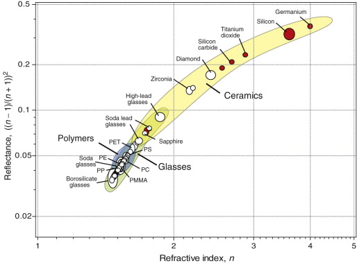
Figure 16.6 A chart of refractive index and reflectance. The materials with open circles are transparent to visible light; those with red circles are transparent to infrared and below, but not to visible radiation. Diamond is special because of its high refractive index, reflectance and transparency in the visible spectrum.
16.4 Drilling down: the physics and manipulation of optical properties
Light, like all radiation, is an electromagnetic (e-m) wave. The coupled fields are sketched in Figure 16.7. The electric part fluctuates with a frequency ν that determines where it lies in the spectrum of Figure 16.1. A fluctuating electric field induces a fluctuating magnetic field that is exactly π/2 out of phase with the electric one, because the induction is at its maximum when the electric field is changing most rapidly. A plane-polarised beam looks like this one: the electric and magnetic fields lie in fixed planes. Natural light is not polarised; then the wave also rotates so that the plane containing each wave continuously changes.
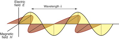
Figure 16.7 An electromagnetic wave. The electric component (gray) is π/2 out of phase with the magnetic component (red).
Many aspects of radiation are most easily understood by thinking of it as a wave. Others need a different picture—that of radiation as discrete packets of energy, photons. The idea of a wave that is also discrete energy units is not intuitive—it is another of the results of quantum theory that do not correspond to ordinary experience. The energy Eph of a photon of radiation of frequency ν or wavelength λ is
where h is Planck’s4 constant (6.626 × 10⁻³⁴ J.s) and c is the speed of the radiation. Thus, radiation of a given frequency has photons of fixed energy, regardless of its intensity—an intense beam simply has more of them. This is the key to understanding reflection, absorption and transmission.
Example 16.3
What is the photon energy of light of wavelength λ = 0.5 µm in vacuum?
Answer. The table on the inside front cover of this book lists Planck’s constant as h = 6.6 × 10⁻³⁴ J.s and the speed of light in vacuum as c = 3 × 10⁸ m/s. The photon energy is ![]() It is more usual to give photon energies in electron volts (eV). An electron volt (eV) is the energy of an electron after it has fallen through a potential difference of 1 volt: thus 1 eV = 1.6 × 10⁻¹⁹ J (it is listed in the Energy table on the inside back cover). Thus the energy of a photon of light of wavelength 0.5 µm is
It is more usual to give photon energies in electron volts (eV). An electron volt (eV) is the energy of an electron after it has fallen through a potential difference of 1 volt: thus 1 eV = 1.6 × 10⁻¹⁹ J (it is listed in the Energy table on the inside back cover). Thus the energy of a photon of light of wavelength 0.5 µm is
Why aren’t metals transparent?
Recall from Chapter 14 that the electrons in materials circle their parent atom in orbits with discrete energy levels, and only two can occupy the same level. Metals have an enormous number of very closely spaced levels in their conduction band; the electrons in the metal only fill part of this number. Filling the levels in a metal is like pouring water into a container until it is part full—its surface is the Fermi5 level; levels above it are empty. If you ‘excite’ the water—say, by shaking the container—some of it can slosh to a higher level. If you stop sloshing, it will return to its Fermi level.
Radiation excites electrons; and in metals there are plenty of empty levels in the conduction band into which they can be excited. But here quantum effects cut in. A photon with energy hν can excite an electron only if there is an energy level that is exactly hν above the Fermi level—and in metals there is. So all the photons of a light beam are captured by electrons of a metal, regardless of their wavelength. Figure 16.8 shows, on the left, what happens to just one.
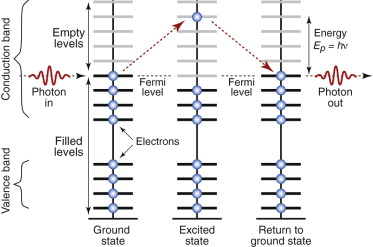
Figure 16.8 Metals absorb photons, capturing their energy by promoting an electron from the filled part of the conduction band into a higher, empty level. When the electron falls back, a photon is re-emitted.
What next? Shaken water settles back, and electrons do the same. In doing so it releases a photon with exactly the same energy that excited it in the first place, but in a random direction. Any photons moving into the material are immediately recaptured, so none makes it more than about 0.01 µm (about 30 atom diameters) below the surface. All, ultimately, re-emerge from the metal surface—that is, they are reflected. Many metals—silver, aluminum and stainless steel are examples—reflect all wavelengths almost equally well, so if exposed to white light they appear silver. Others—copper, brass, bronze—reflect some colors better than others and appear colored because, in penetrating this tiny distance into the surface, some wavelengths are slightly absorbed.
Reflection by metals, then, has to do with electrons at the top of the conduction band. These same electrons provide electrical conduction. For this reason, the best metallic reflectors are the metals with the highest electrical conductivities—the reason that high-quality mirrors use silver and cheaper ones use aluminum.
How does light get through dielectrics?
If electrons snatch up photons, how is that some materials are transparent—light goes straight through them? Nonmetals interact with radiation in a different way. Part may be reflected but much enters the material, inducing both dielectric and magnetic responses. Not surprisingly, then, the velocity of an e-m wave depends on the dielectric and magnetic properties of the material through which it travels. In a vacuum the velocity is
where εo is the electric permittivity of a vacuum and μo its magnetic permeability, defined in Chapters 14 and 15. Within a material its velocity is

where ε = εRεo and μ = μRμo are the permittivity and permeability of the material. The refractive index, therefore, is
The relative permeability μR of most dielectrics is very close to unity—only the magnetic materials of Chapter 15 have larger values. Thus,
The chart of Figure 16.5 has n as one axis and εR as the other. The diagonal line is a plot of this equation (the log scales make it a straight line). Polymers and very pure materials like diamond, silicon and germanium lie close to the line but the agreement with the rest is not so good. This is because refractive index and dielectric constant depend on frequency. Refractive index is usually measured optically, and that means optical frequencies, around 1015 Hz. Dielectric constants are more usually measured at radio frequencies or below—106 Hz or less. If the two are measured at the same frequency, equation (16.13) holds.
Example 16.4
A dielectric material has a high-frequency dielectric constant of εR = 3.5. What would you estimate its refractive index to be?
The reason that radiation of certain wavelengths can enter a dielectric is that its Fermi level lies at the top of the valence band, just below a band gap (Chapter 14 and Figure 16.9). The conduction band, with its vast number of empty levels, lies above it. To excite an electron across the gap requires a photon with an energy at least as great as the width of the gap, ΔEgap. Thus, radiation with photon energy less than ΔEgap cannot excite electrons—there are no energy states within the gap for the electron to be excited into. The radiation sees the material as transparent, offering no interaction of any sort, so it goes straight through.
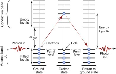
Figure 16.9 Dielectrics have a full band, separated from the empty conduction band by an energy gap. The material cannot capture photons with energy less than ΔEgap, meaning that, for those frequencies, the material is transparent. Photons with energy greater than ΔEgap are absorbed, as illustrated here.
Electrons, however, are excited by radiation with photon energie greater than ΔEgap (i.e. higher frequency, shorter wavelength). These have enough energy to pop electrons into the conduction band, leaving a ‘hole’ in the valence band from which they came. When they jump back, filling the hole, they emit radiation of the same wavelength that first excited them, and for these wavelengths the material is not transparent (Figure 16.9, right-hand side). The critical frequency νcrit, above which interaction starts, is given by
The material is opaque to frequencies higher than this. Thus, bakelite is transparent to infrared light because its frequency is too low and its photons too feeble to kick electrons across the band gap, but the visible spectrum has higher frequencies with more energetic photons, exceeding the band gap energy; they are captured and reflected.
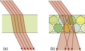
Although dielectrics can’t absorb radiation with photons of energy less than that of the band gap, they are not all transparent. Most are polycrystalline and have a refractive index that depends on direction; then light is scattered as it passes from one crystal to another. Imperfections, particularly porosity, do the same. Scattering, sketched in Figure 16.10, makes the material appear translucent or even opaque, even though, when made as a perfect single crystal, it is completely transparent. Thus, sapphire (alumina, Al2O3), used for watch crystals and cockpit windows of aircraft, is transparent, but the polycrystalline, slightly porous form of the same material that is used for electronic substrates is translucent or opaque. Scattering explains why some polymers are translucent or opaque: their microstructure is a mix of crystalline and amorphous regions with different refractive indices. It explains, too, why some go white when you bend them: it is because light is scattered from internal microcracks—the crazes described in Chapter 6.
Color
If a material has a band gap with an energy ΔEgap that lies within the visible spectrum, the wavelengths with energy greater than this are absorbed and those with energy that is less are not. The absorbed radiation is re-emitted when the excited electron drops back into a lower energy state, but this may not be the one it started from, so the photon it emits has a different wavelength than the one that was originally absorbed. The light emitted from the material is a mix of the transmitted and the re-emitted wavelengths, and it is this that gives it a characteristic color.
More specific control of color is possible by doping—the deliberate introduction of impurities that create a new energy level in the band gap, as in Figure 16.11. Radiation is absorbed as before but it is now re-emitted in two discrete steps as the electrons drop first into the dopant level, emitting a photon of frequency ν1 = ΔE1/h and from there back into the valence band, emitting a second photon of energy ν2 = ΔE2/h. Particularly pure colors are created when glasses are doped with metal ions: copper gives blue; cobalt, violet; chromium, green; manganese, yellow.
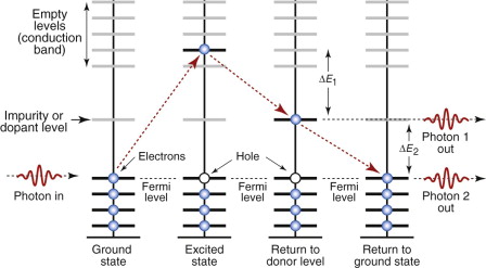
Figure 16.11 Impurities or dopants create energy levels in the band gap. Electron transitions to and from the dopant level emit photons of specific frequency and color.
Example 16.6
An insulator has a dopant-created energy level that lies ΔE = 2.1 eV below the conduction band. If electrons are excited into the conduction band and fall back into this level, what is the wavelength of the radiation that is emitted? Is it in the optical spectrum? If so, what is its colour?
Answer. The frequency of the emitted radiation is ![]()
Its wavelength is ![]() . Referring to Figure 16.1, this corresponds to a colour in the green part of the spectrum.
. Referring to Figure 16.1, this corresponds to a colour in the green part of the spectrum.
Fluorescence, phosphorescence and electro luminescence
Electrons can be excited into higher energy levels by incident photons, provided they have sufficient energy. Energetic electrons, like those of the electron beam of a cathode ray tube, do the same. In most materials the time delay before they drop back into lower levels, re-emitting the energy they captured, is extremely short, but in some there is a delay. If, on dropping back, the photon they emit is in the visible spectrum, the effect is that of luminescence—the material continues to glow even when the incident beam is removed. When the time delay is fractions of seconds, it is called fluorescence, used in fluorescent lighting, where it is excited by ultraviolet from a gas discharge, and in TV tubes where it is excited by the scanning electron beam. When the time delay is longer it is called phosphorescence; it is no longer useful for creating moving images but is used instead for static displays like that of watch faces, where it is excited by electrons (β-particles) released by a mildly radioactive ingredient in the paint.
Photo-conductivity
Dielectrics are true insulators only if there are no electrons in the conduction band, since if there are any, a field will accelerate them, giving an electric current. Dielectrics with a band gap that is sufficiently narrow that the photons of visible light excite electrons across it become conducting (though with high resistance) when exposed to light. The greater the intensity of light, the greater the conductivity. Photo light-meters use this effect; the meter is simply a bridge circuit measuring the resistance of a photo-conducting element such as cadmium sulfide.
16.5 Optical design
Using reflection and refraction
Telescopes, microscopes, cameras and car headlights all rely on the focusing of light. Reflecting telescopes and car headlights use metallised glass or plastic surfaces, ground or moulded to a concave shape; the metal, commonly, is silver because of its high reflectivity across the entire optical spectrum.
Refracting telescopes, microscopes and cameras use lenses. Here the important property is the refractive index and its dependence on wavelength (since, if this is large, different wavelengths of light are brought to a focus in different planes), and the reflectivity (since reflected light is lost and does not contribute to the image). As the chart of Figure 16.5 shows, most elements and compounds have a fixed refractive index. Glasses are different: their refractive index can be tuned to any value between 1.5 and more than 2. Adding components with light elements like sodium (as in soda-lime glass) gives a low refractive index; adding heavy elements like lead (as in lead glass or ‘crystal’) gives a high one.
Using total internal reflection
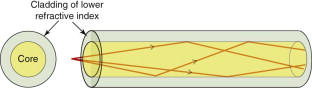
Optical fibres have revolutionised the digital transmission of information: almost all landlines now use these rather than copper wires as the ‘conductor’. A single fibre consists of a core of pure glass contained in a cladding of another glass with a lower refractive index, as in Figure 16.12. A digitised signal is converted into optical pulses by a light-emitting diode and is fed into the fibre, where it is contained within the core, even when the fibre is bent, because any ray striking the core–cladding interface at a low angle suffers total internal reflection. The purity of the core—a silica glass—is so high that absorption is very small; occasional repeater stations are needed to receive, amplify and retransmit the signal to cover long distances.
16.6 Summary and conclusions
Materials interact with electromagnetic radiation in several ways: reflecting it, refracting it and absorbing it. This is because radiation behaves both as a wave of frequency ν and as a stream of discrete photons with energy Eph = hν. Electrons in materials capture photons, grabbing their energy, provided there are energy levels exactly Eph above their ground state for them to occupy. After a time delay that is usually very short, the electrons drop back down to their ground state, re-emitting their energy as new photons. In metals there are always usable energy levels so every photon hitting a metal is captured and thrown back out, giving reflection. In a dielectric, the atoms ignore low-frequency, low-energy photons and capture only those with energy above a critical level set by the band gap. Those that are not caught pass straight through; for these frequencies, the material is transparent. Doping introduces extra slots within the band gap for electrons to fall into as they release their energy, and in doing so they emit photons of specific frequency and colour.
When radiation enters a dielectric, it slows down. A consequence of this is that a beam entering at an angle is bent—the phenomenon of refraction. It is this that allows light to be focused by lenses, reflected by prisms and trapped in fine, transparent fibres to transmit information.
Of all the transparent materials at our disposal, glasses offer the greatest range of refractive index and colour. Glasses are based on amorphous silica, SiO2. Silica is an extremely good solvent, allowing a wide range of other oxides to be dissolved in it over a wide range of concentrations. It is this that allows the optical properties of glasses to be adjusted and fine-tuned to match design needs.
Callister W.D.Jr. Materials Science and Engineering, an Introduction 6th ed. 2003 John Wiley New York, USA ISBN 0-471-13576-3. (A well-established and comprehensive introduction to the science of materials.)
Jiles D. Introduction to the Electronic Properties of Materials 2001 Nelson Thompson Cheltenham, UK ISBN 0-7487-6042-3. (A refreshingly direct approach to the thermal, electrical, magnetic and optical properties of materials and their electronic origins.)
16.8 Exercises
- Exercise E16.1 Define refractive index. Give examples of devices that make use of refraction.
- Exercise E16.2 Define reflectance. Give examples of devices that make use of reflection.
- Exercise E16.3 The absorption coefficient of polyethylene for optical frequencies is 86.6 m−1. How thick a slab of polyethylene is required to reduce the transmitted light intensity to one-half of its initial value?
- Exercise E16.4 Why are metals good reflectors of radiation?
- Exercise E16.5 It is proposed to replace soda glass windows of a greenhouse with polycarbonate (PC). Will the PC windows reflect more? The refractive index of the glass is 1.5 and that of PC 1.6.
- Exercise E16.6 Waterford glass and Steuben glass, used for expensive ornamental and cut-glass objects, are high-lead glasses, meaning that they contain oxides of lead. Using the information shown on the chart of Figure 16.6, can you explain the choice of composition?
- Exercise E16.7 An X-ray system has a beryllium window to transmit the beam. The absorption coefficient of beryllium for the wavelength of X-rays of interest here is 3.02 × 10² m−1. If the window is 2 mm thick, what fraction of the incident beam intensity will pass through the window? The rest of the equipment is shielded with 4 mm of lead, with absorption coefficient for X-rays of 3.35 × 10⁶ m−1. What fraction of the intensity of the incident beam will escape through the casing?
- Exercise E16.8 What principle and material would you choose to make a light-sensing switch for a greenhouse?
- Exercise E16.9 What principle and material would you choose to make a heat-sensing switch to turn the lights off in the garage when no one is moving around in it?
- Exercise E16.10 An optical fibre has a glass core with a refractive index of n1 = 1.48, clad with a glass with refractive index n2 = 1.45. What is the maximum angle that the incoming optical signal can deviate from the axis of the core while still remaining trapped in it?
16.9 Exploring design with CES (use Level 2 unless otherwise stated)
- Exercise E16.11 Use the ‘Search’ facility to find materials for:
Exercise E16.12 Explore the best choice of cheap polymer for a new line of injection-moulded costume jewelry. Its transparency must be of optical quality, and it should have the highest possible refractive index. The table summarises the requirements.
Function •Plastic costume jewelry Constraints •Transparency of optical quality •Injection mouldable •Price <5 $/kg Objective •Maximise refractive index Free variable •Choice of material Exercise E16.13 A material is required for the mirror backing of a precision reflecting telescope. It must have a modulus of at least 50 GPa so that it does not deflect under its own weight; it must be hard so that the surface (which will be silvered), once ground, does not distort; it must have the lowest possible thermal expansion to minimise thermal distortion and it must be able to be moulded or cast to its initial shape before grinding. Use CES to find suitable candidates.
Function •Mirror backing Constraints •Young’s modulus >50 GPa •Processing: mouldability 5 Objective •Highest hardness with lowest thermal expansion coefficient Free variable •Choice of material - Exercise E16.14 Find materials that are optically clear, have a mouldability rating of 5 and have excellent resistance to fresh and to salt water for use as contact lenses.
16.10 Exploring the science with CES Elements
Exercise E16.15 The Hagen–Rubens law—an empirical law—says that the reflectivity of metals, R, is given by
(where the electrical resistivity ρe is in µΩ.cm). Make a chart with R on the y-axis and electrical conductivity 1/ρe on the x-axis. Use it to find the three elements with the highest reflectivities.
Exercise E16.16 The text explained why the refractive index n was related to the dielectric constant εR by the equation
Make a chart with
 on the x-axis and n on the y-axis for the elements to see how accurate this relationship is. Which elements best obey it?
1 Albert A. Michelson (1852–1931), Prussian-American experimental physicist, who, with E. W. Morley, first demonstrated that the speed of light is independent of the earth’s motion, a finding central to the establishment of the theory of relativity.
2 Willebrord Snell (1591–1626), Dutch astronomer, also known as Snell van Royen, or Snellius, who first derived the relationship between the different angles of light as it passes from one transparent medium to another. The lunar crater Snellius is named after him.
3 Augustin Jean Fresnel (1788–1827), French physicist and engineer, known for his research on the wave theory of light and of diffraction and polarisation.
4 Max Karl Ernst Ludwig Planck (1858–1947), a central figure in the development of quantum theory; it was he who formulated equation (16.9).
5 Enrico Fermi (1901–1954), devisor of the statistical laws known as Fermi statistics governing the behaviour of electrons in solids. He was one of the leaders of the team of physicists on the Manhattan Project for the development of the atomic bomb.