Chapter 5: Building a Sumobot
Sumobots and battlebots are both terms that you may have heard of before. In case you don't know what sumobots are, they are basically robots that are designed to battle one another. Basically, it is a sport where two robots battle in a head-to-head competition to outlast the other robot. Battle robots are a classic build challenge for any robot enthusiast. The popular TV show, Battle Bots, that has led to shows that are now on TV, Twitch, and other platforms, you can find robots battling in all types of arenas, with designs based on just about every conceivable idea you can imagine. These robots come in all shapes and sizes, depending on the rules of the competition. These robot challenges are quite popular in schools, after-school programs, and summer camps when it comes to sumobots. The robot you will build in this chapter will provide you with a solid foundation for being dominant in your next arena battle.
Here is a picture of what your sumobot will look like by the end of this chapter:
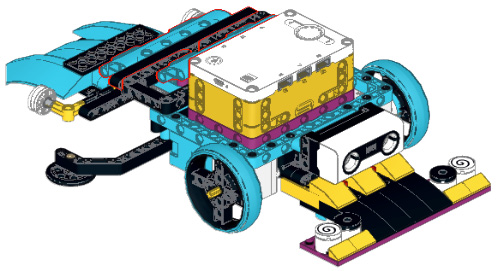
Figure 5.1 – Sumobot
In this chapter, you will break down the build and program as follows:
- Building the base
- Building the ultrasonic sensor and color sensor attachment
- Building the force sensor attachment
- Writing the code
- Making it your own
Technical requirements
For the building of the robot, all you will need is the LEGO SPIKE Prime kit. For programming, you will need the LEGO SPIKE Prime app/software.
Access to code can be found here: https://github.com/PacktPublishing/Design-Innovative-Robots-with-LEGO-SPIKE-Prime/blob/main/Sumo.llsp.
You can find the code in action video for this chapter here: https://bit.ly/3oTqWmI
Let's start building!
Building the base
The beauty of this robotics kit is that you can easily get started with any type of build because of the new pieces that are included. There are a lot of different options, depending on the strategy and size of your sumobot.
For this robot, the following strategies and constraints were used in the design:
- The body frame needs to be open for any user to remix, add to, and modify to their liking.
- The sumobot strategy is to identify the other robot and use sensors to push the other robot out of the arena using the little scoops at the front and back to slightly lift and push the robot.
- The robot needs to be low to the ground to keep the weight distribution and center of gravity low to avoid falling over.
To begin, you will add eight black connector pins to an azure 11x15 open frame:
- Place four on each side, according to Figure 5.2. These are placed to allow the motors to be added:

Figure 5.2 – The main frame of the robot body
- Attach two medium motors to the black connector pins. Add a black 15L beam across the backside of the open frame using two more black connector pins:
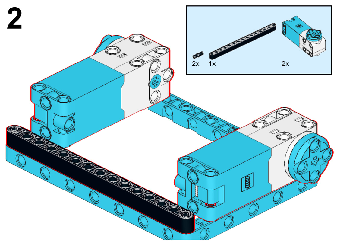
Figure 5.3 – Attaching the motors
- Flip the frame over so the motors are on the underside:
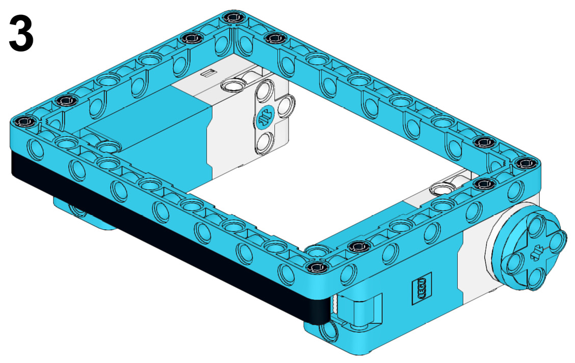
Figure 5.4 – Flipping the frame over
- Insert four black connector pins into the corners of the medium motors:
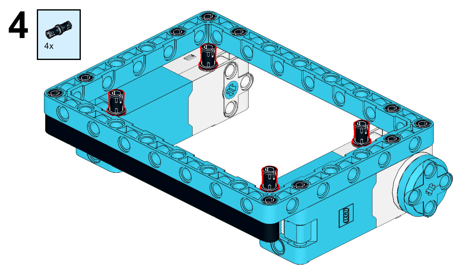
Figure 5.5 – Inserting the black connector pins into the medium motors
- Add a purple 7x11 open frame to the black connector pins. Add four more black connector pins to the purple 7x11 open frame. These will be used to attach the Intelligent Hub:
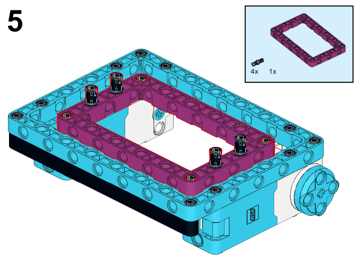
Figure 5.6 – Attaching a purple 7x11 open frame
- Attach the Intelligent Hub to the purple 7x11 open frame using the four black connector pins:

Figure 5.7 – Attaching the Intelligent Hub
The simple but secure base has now been completed. It is time to build and attach the ultrasonic sensor attachment.
Building the ultrasonic sensor attachment
You are now going to add the ultrasonic sensor so that during competition, your robot can detect the opponent:
- Add two black connector pins to the azure 11x15 open frame where the motors are positioned and then add an azure 7L beam to these pins. Next, add two more black connector pins to the end pin holes of this beam:
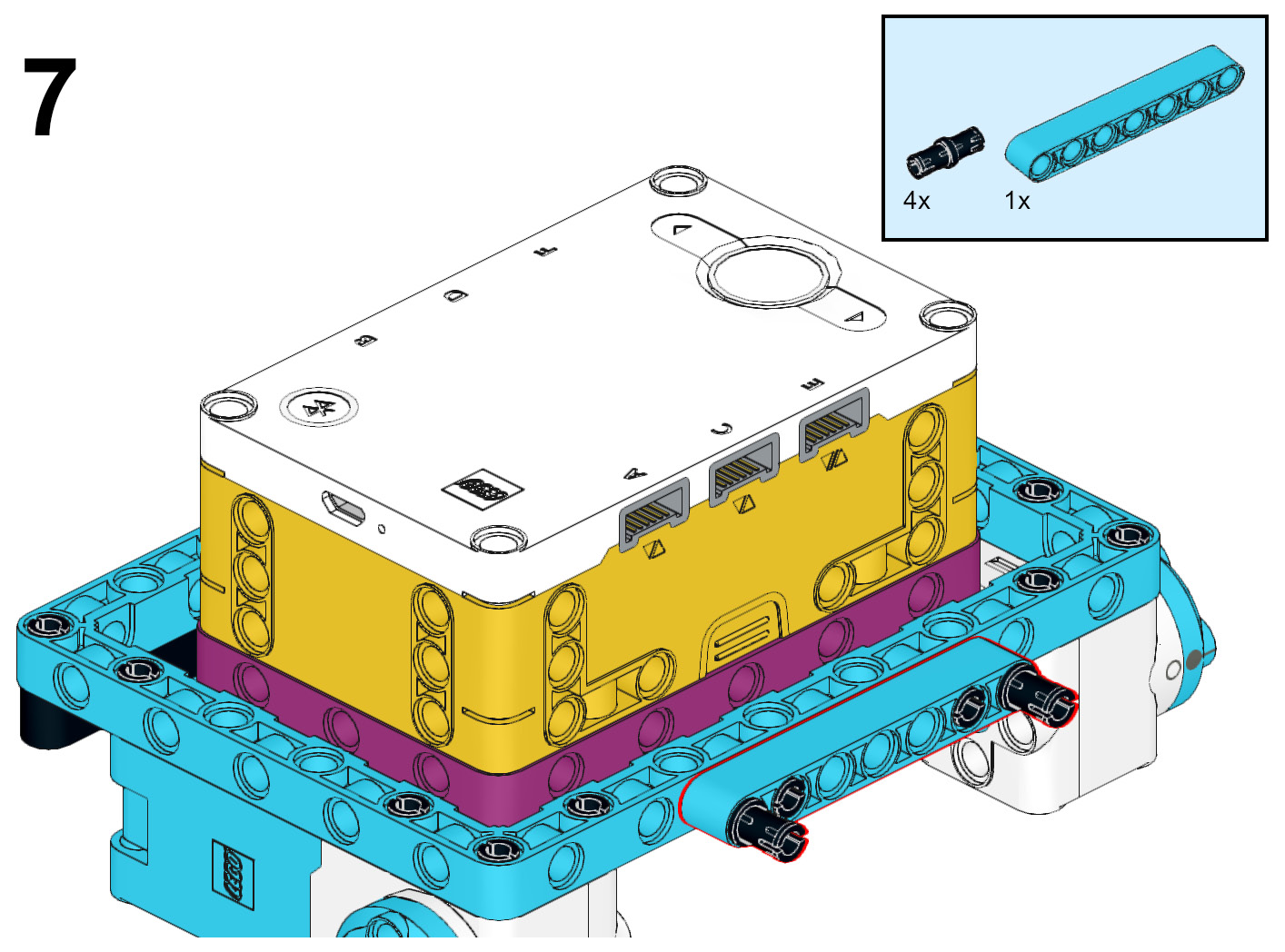
Figure 5.8 – Attaching the 7L beam to the frame
- Connect the ultrasonic sensor to the robot by using the two black connector pins:
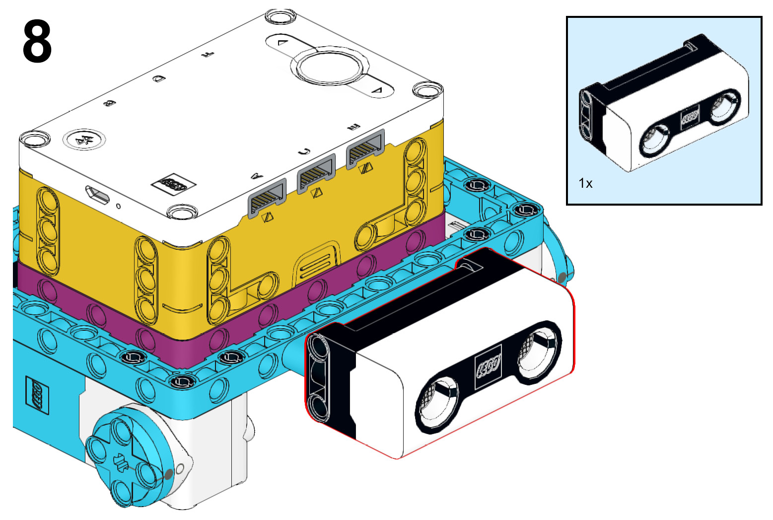
Figure 5.9 – Connecting the ultrasonic sensor
- You are now going to build a sub-model that will eventually connect underneath the ultrasonic sensor using the following steps:
- Place two purple 2x16 plates side by side.
- Secure them together using four white 2x2 round bricks.
- Add four yellow 1x2 slopes on the ends to serve as a bumper to lift up your robot opponent in battle:

Figure 5.10 – Building the plow for the front
- It is time to add another layer to the plow using the following steps:
- Attach four of the black 2x6 slopes to the purple plates. This strengthens the scoop and helps hold everything together.
- Add three yellow 2x3 slopes to the tops of the black 2x6 slopes:
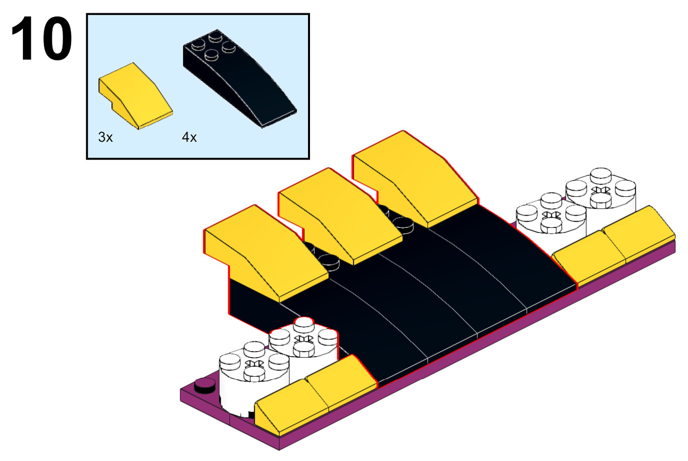
Figure 5.11 – Adding another layer to the plow
- Add three 2x4 bricks to the underside of the yellow 2x3 bricks. The outside yellow 2x4 bricks are parallel with the black curved panels. The red 2x4 brick is perpendicular to the black curved panel:
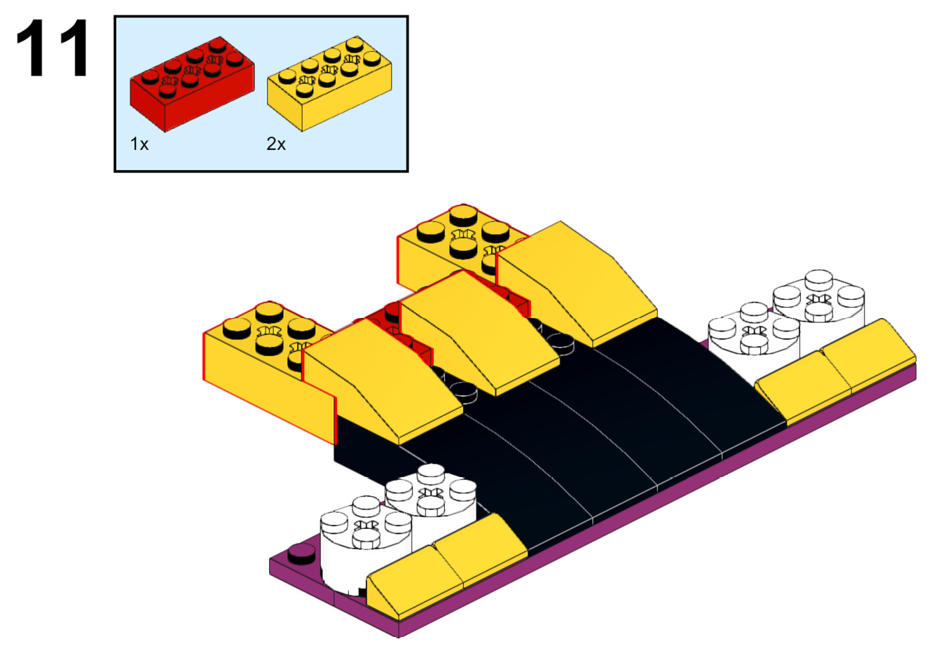
Figure 5.12 – Attaching 2x4 bricks to the underside of the yellow slopes
- The following set of steps will focus on the underside of the robot. Begin by flipping the build over:
- Add a black 2x8 plate to the yellow 2x4 bricks.
- Hold things in place by adding four azure 2x2 round plates across the black 2x8 plate and the black 2x6 slopes:
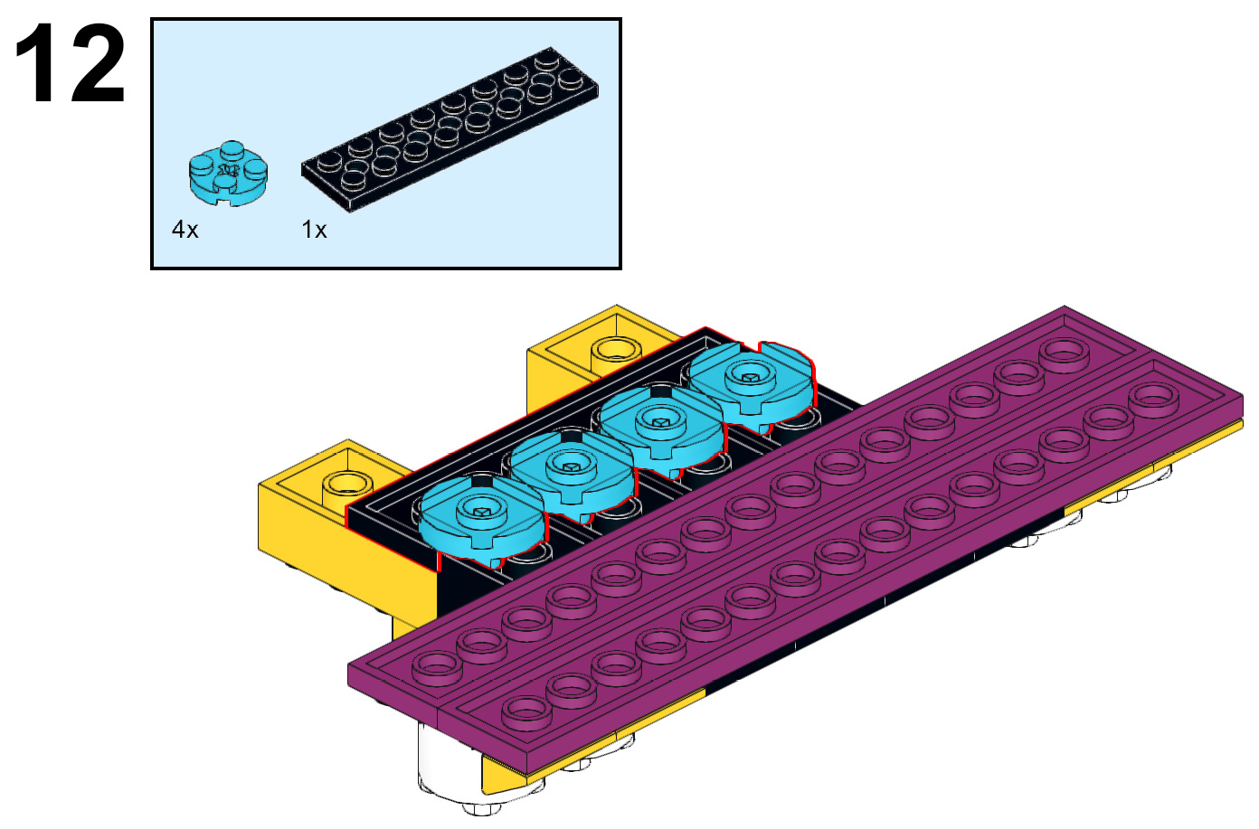
Figure 5.13 – Securing the parts of the plow
- Flip this model back over and add two white spiral tiles and two black tiles for some decorative touches:
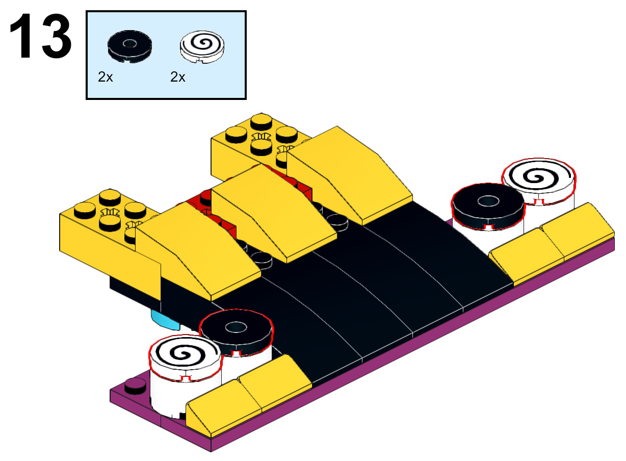
Figure 5.14 – Adding some design to the plow
- Before you build the next part of the plow that houses the color sensor, here is how it should look now:
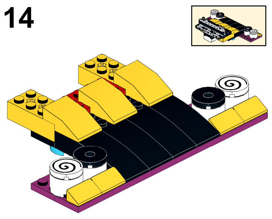
Figure 5.15 – A view of the front plow
- You are going to build another sub-model that will attach to the plow you just built. This sub-model houses the color sensor. The steps are as follows:
A. Add two black connector pins to the two black biscuit elements. Add one connector pin to the outside top pin hole and another to the side pin hole.
B. Add two black connector pins to the color sensor:
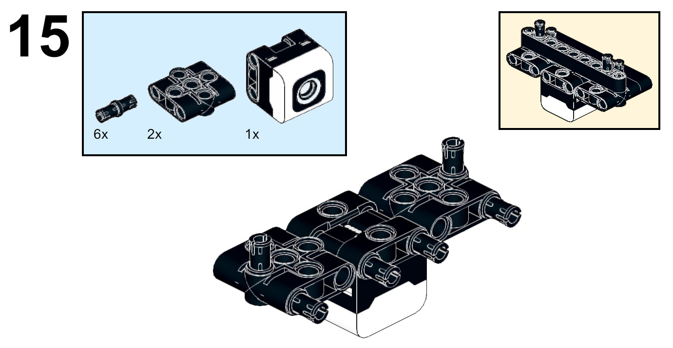
Figure 5.16 – Adding pins to the color sensor model
- Hold the two biscuit elements and color sensor together using two black 9L beams by attaching them to the black connector pins. On the exposed pin hole of the black biscuit elements, insert a black pin and an axle connector. These will not stay secure now, but you will take care of that in the next step:
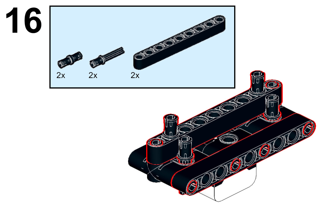
Figure 5.17 – Securing the parts together
- Using the black pin and axle connector pins from the previous step, attach this color sensor sub-model to the plow by adding it to the axle holes in the yellow 2x4 bricks:
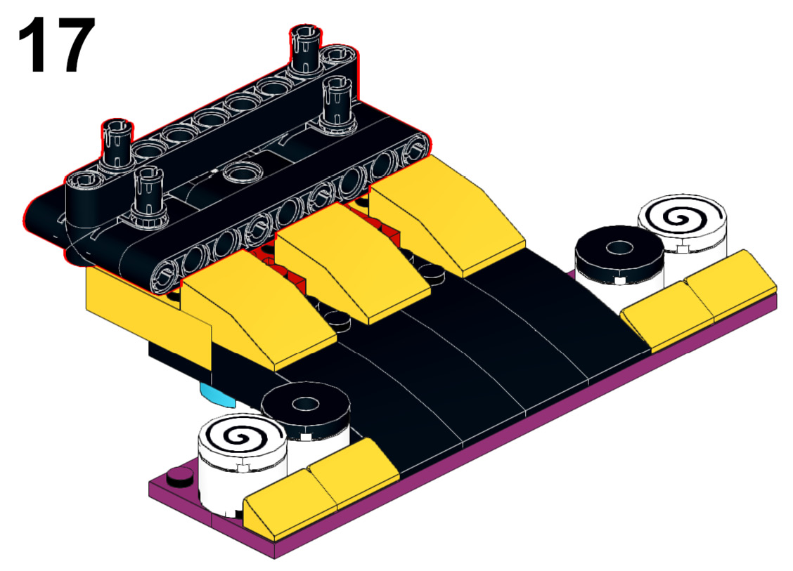
Figure 5.18 – Combining the plow and color sensor sub-models
- This whole sub-model now attaches to the body of the robot. It will join using the black connector pins to the underside of the azure 11x15 open frame between the motors:
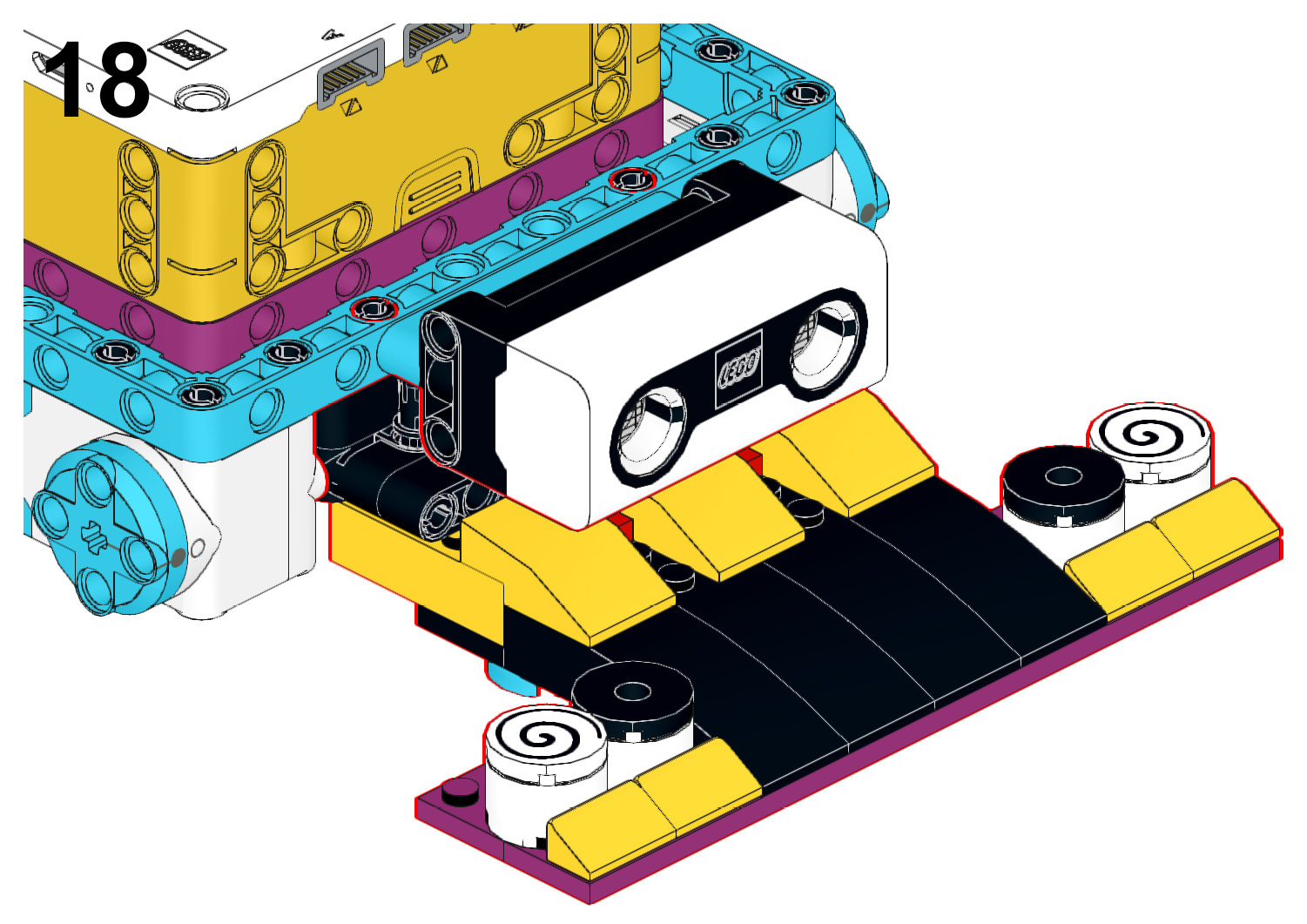
Figure 5.19 – Adding to the main body frame
Now that the front is complete, it is time to begin to build the back attachment using the force sensor.
Building the force sensor attachment
Before we add the force sensor, the robot needs to be lifted up with wheels and the plastic caster ball element using the following steps:
- To begin this process, connect a gray 3x5 H-shaped beam to the azure caster ball frame using two black connector pins:

Figure 5.20 – Attaching the H frame beam to the caster ball element
- On the top of these two elements, add a purple biscuit element using two blue connector pins:
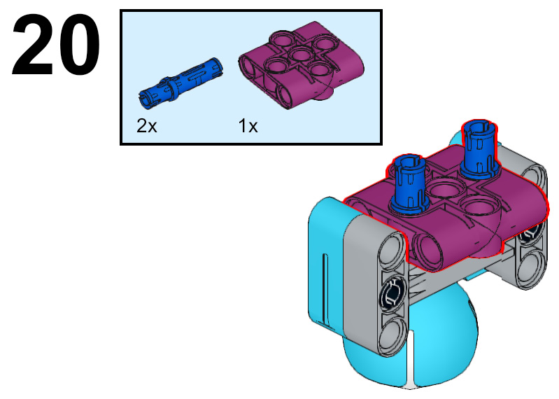
Figure 5.21 – Add a biscuit element to the top
- This sub-model will attach to the underside of the robot body to the purple 7x11 open frame. This element is placed opposite to the color sensor:
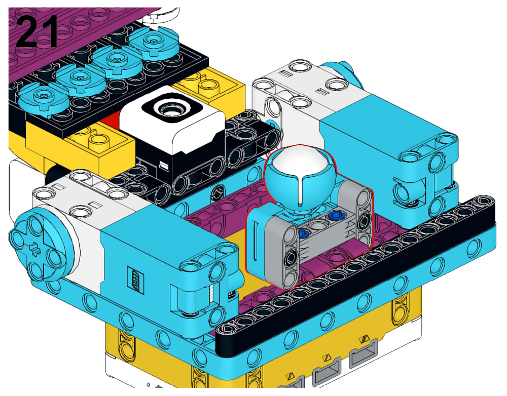
Figure 5.22 – Attaching the caster wheel to the underside of the robot
- Next, turn the sumobot back to the original position. You will add a wheel to each of the medium motors. Attach a wheel using two black connector pins and one yellow 3L axle:
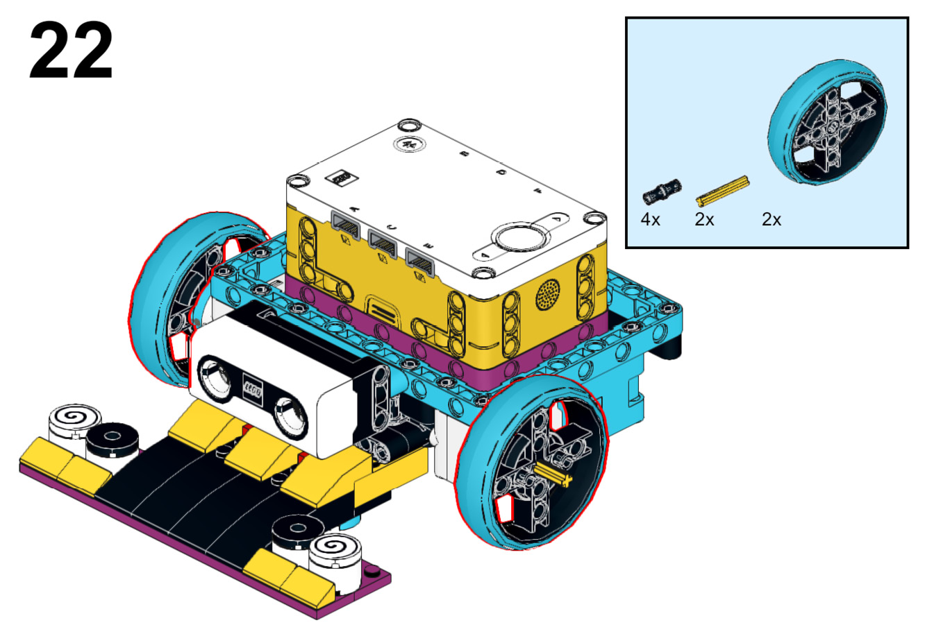
Figure 5.23 – Adding the wheels
Your robot should not be balanced and ready for action. Before you move into action, you need to add the force sensor attachment using the following steps:
- Begin by connecting the force sensor to the backside of the robot body using two gray perpendicular connector elements. Add these elements to the sensor first and then connect collectively to the black 15L beam on the robot body frame:
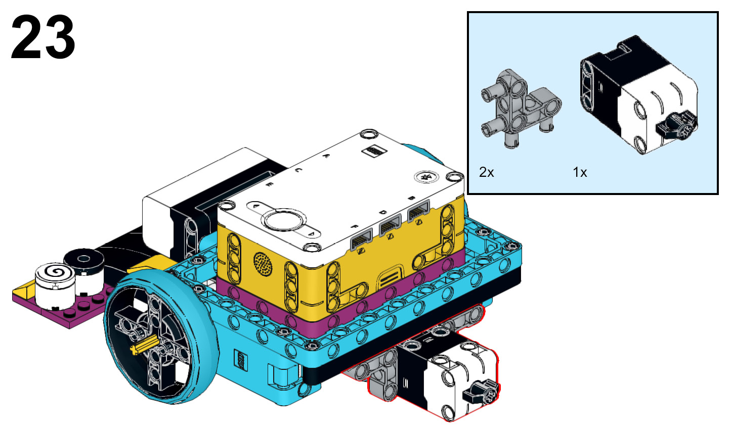
Figure 5.24 – Attaching the force sensor to the body
- It is time to build out the bumper for the sensor so that your robot can feel the impact from any angle of attack:
A. Start with a black 15L beam.
B. Insert a black pin and axle connector pin to the middle pin hole with the axle element being exposed.
C. Insert two black connector pins on either side of this pin.
D. Attach a purple 5L beam to the pins.
E. Insert this build piece into the force sensor:
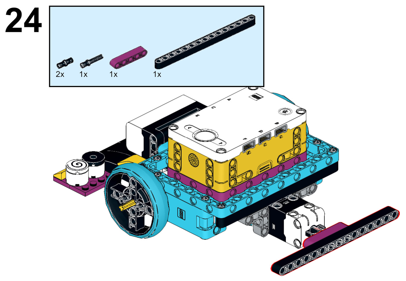
Figure 5.25 – Building out the force sensor bumper
- Insert two black connector pins and two blue connector pins into the black 15L beam, as shown in Figure 5.26:
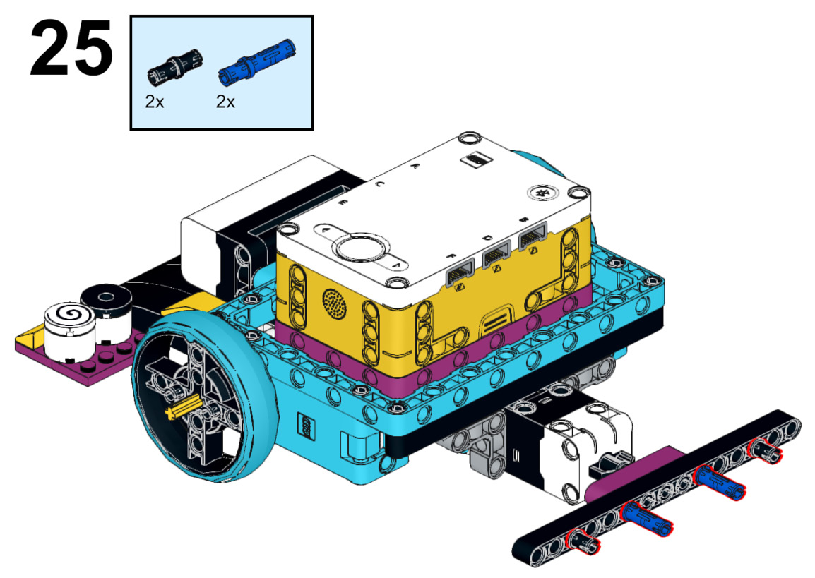
Figure 5.26 – Adding the connector pins
- To help the bumper work to activate the force sensor, you need to add some additional elements:
A. Begin with a yellow axle and pin connector #6, and add a red axle connector pin to one end.
B. Attach a black axle and pin connector #2 to the red axle connector pin, and add another red axle connector to the other end.
C. Attach another yellow axle and pin connector #6 facing outward. Add a yellow 3L axle to the other end.
D. Slide a gray bush on the yellow 3L axle and a white wheel hub:
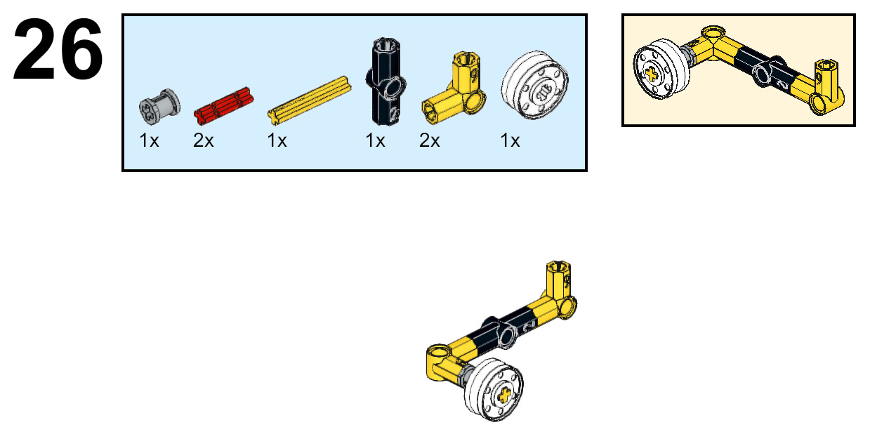
Figure 5.27 – The force sensor bumper extension
- You will do this same build but mirror it for the other side:
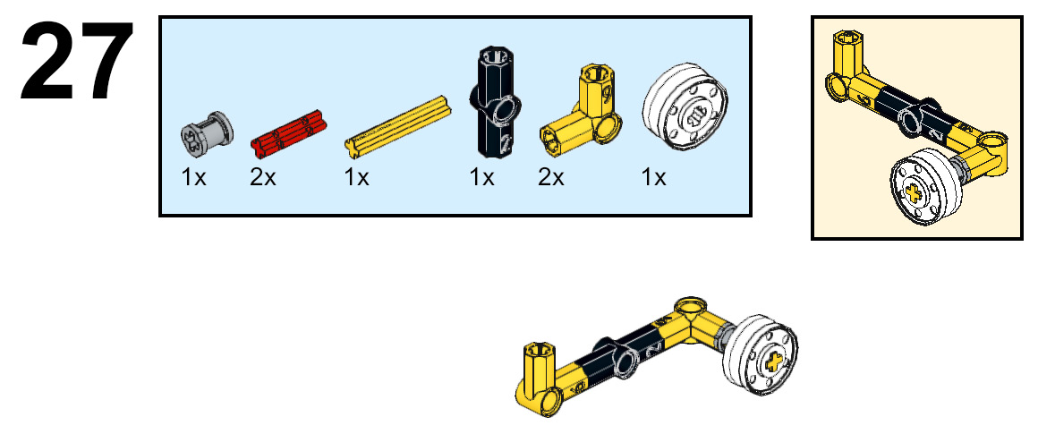
Figure 5.28 – Mirroring the build for the other side
- Attach these two builds to the force sensor bumper using the pins on the black 15L beam:
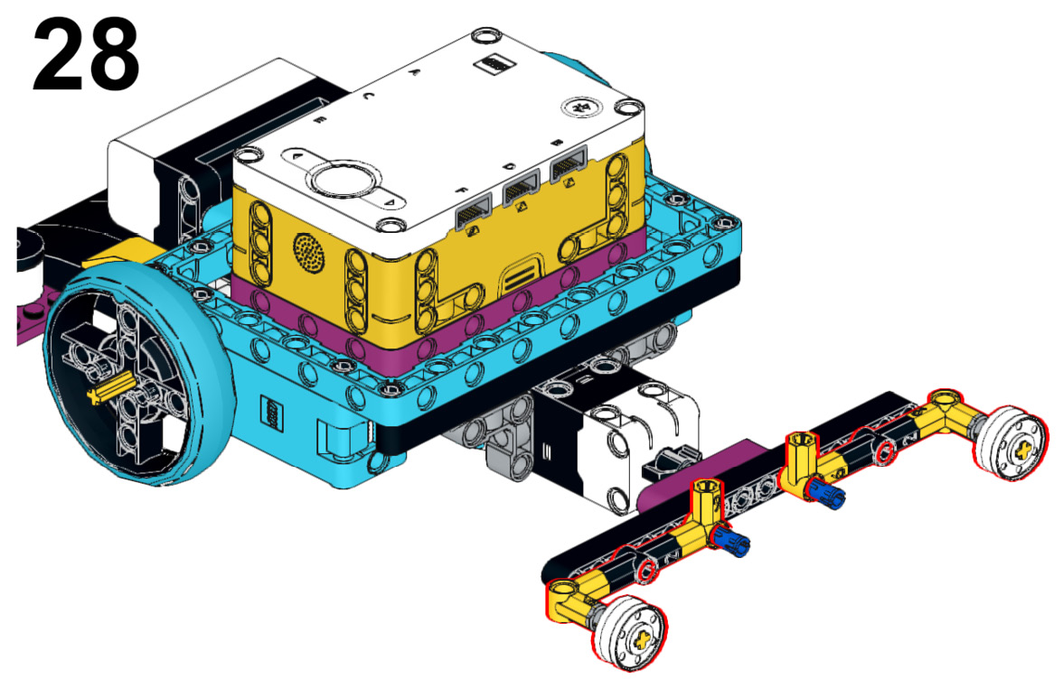
Figure 5.29 – Adding builds to the bumper
- Add an azure 7L beam to the blue pins available on the front of the force sensor bumper. Add two black connector pins to this beam:
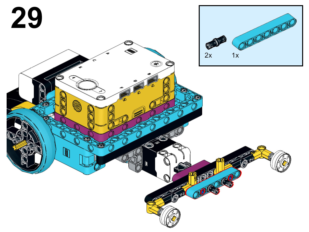
Figure 5.30 – Attaching an azure beam to the front of the bumper
- It is time to add the plow to this sensor attachment using the following steps:
A. Begin by connecting the azure 8x6x2 windscreen element to the black connector pins on the front of the bumper.
B. Attach a black 2x8 plate to the top of the windscreen element.
C. Add an azure 8x3x2 wedge to both sides of the windscreen element.
D. Attach two black 2x8 plates to the bottom of the windscreen element to hold everything in place. Add one to the front and another to the back of these elements:
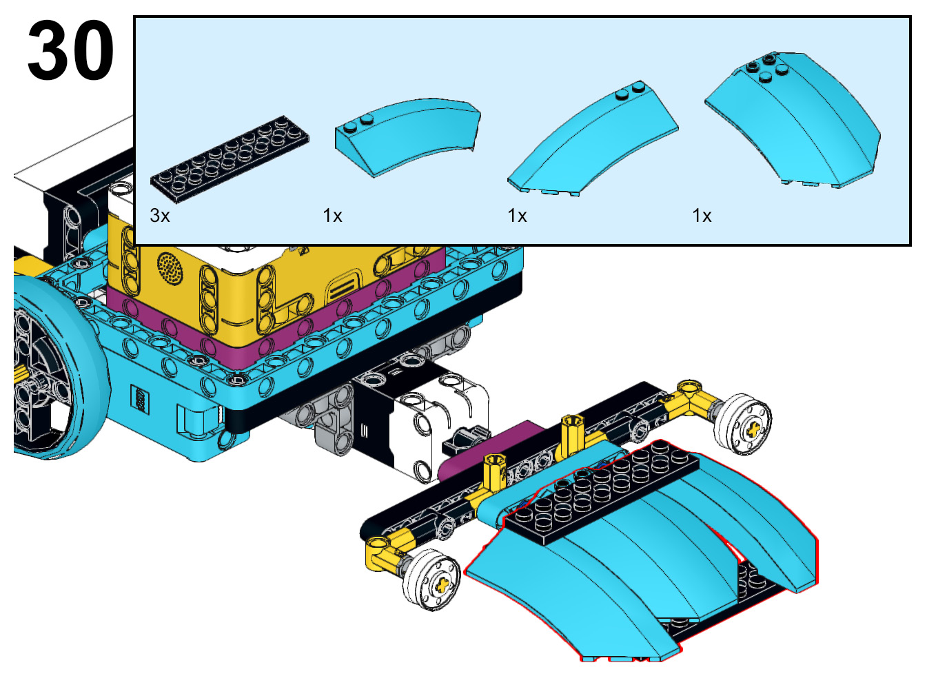
Figure 5.31 – Building the plow for this sensor
- On top of the yellow axle and pin connectors #6, add a tan pin and axle connector. Attach an azure 7L beam to both pins:
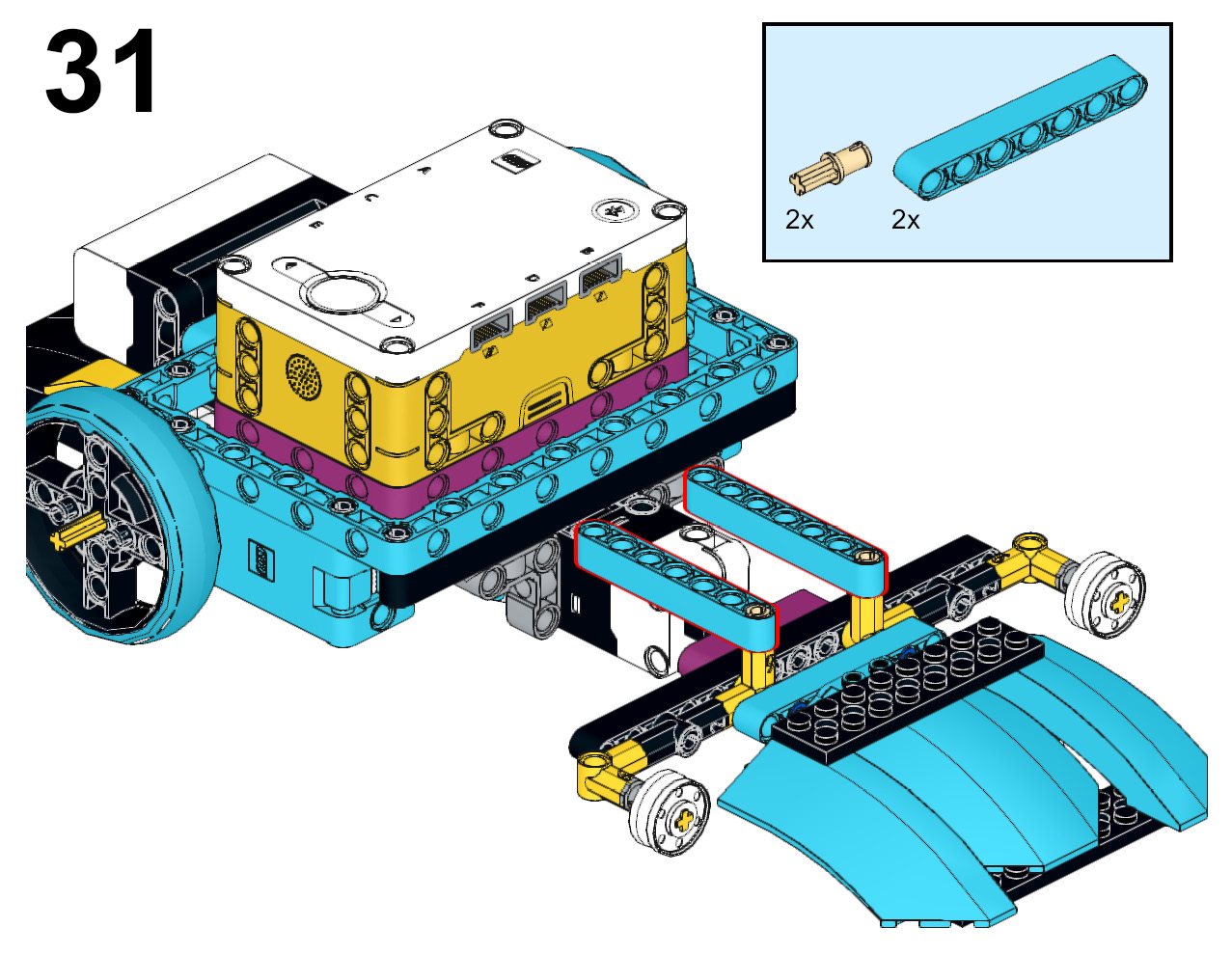
Figure 5.32 – Adding the beam to the top of the plow
- It is time for the final steps to ensure the bumper stays in place:
A. On both the azure 7L beams, add a black connector pin to the end pin hole.
B. Attach a black biscuit element to these pins.
C. Add a purple 5L beam across to connect the azure 7L beams.
D. Do this same process again but on the third pin hole from the end.
E. In the middle pin hole on both purple 5L beams, add a black connector pin.
F. On the underside of the azure 7L beams, insert a gray perpendicular pin connector into both sides.
G. Finally, add a yellow 3L beam to the bottom of both gray perpendicular pin connectors:
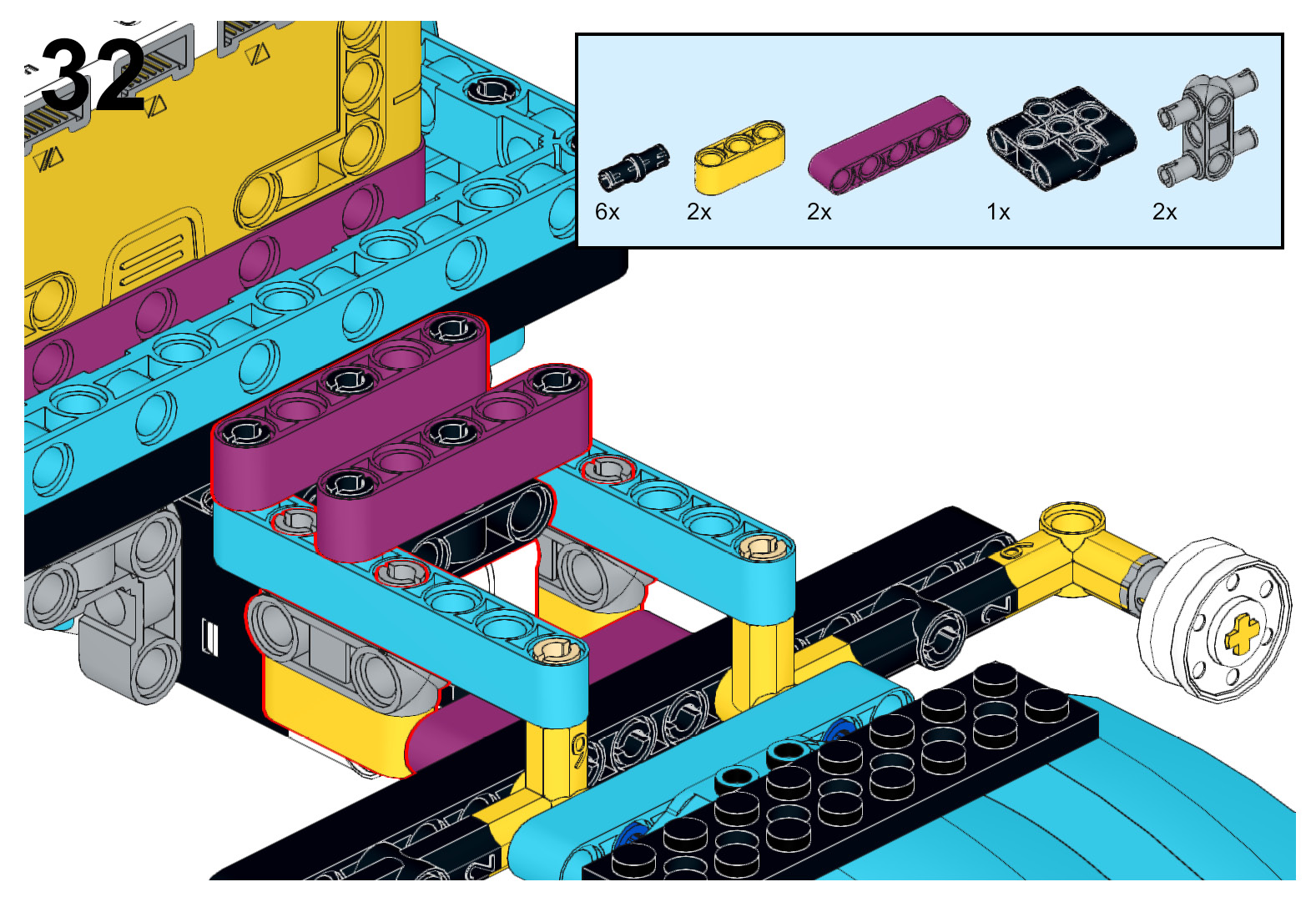
Figure 5.33 – Adding the frame to keep the bumper in place
- You are closing in on the final steps. The next part is to help your robot roll away from an attack as well as to roll an opponent into your bumper for your own attack.
Begin by adding a blue connector pin to a black double-bent lift-arm beam. Do this two times – once for the right side and once for the left side of your robot. Do not connect to the robot yet. The figure is to give you a sense of location:
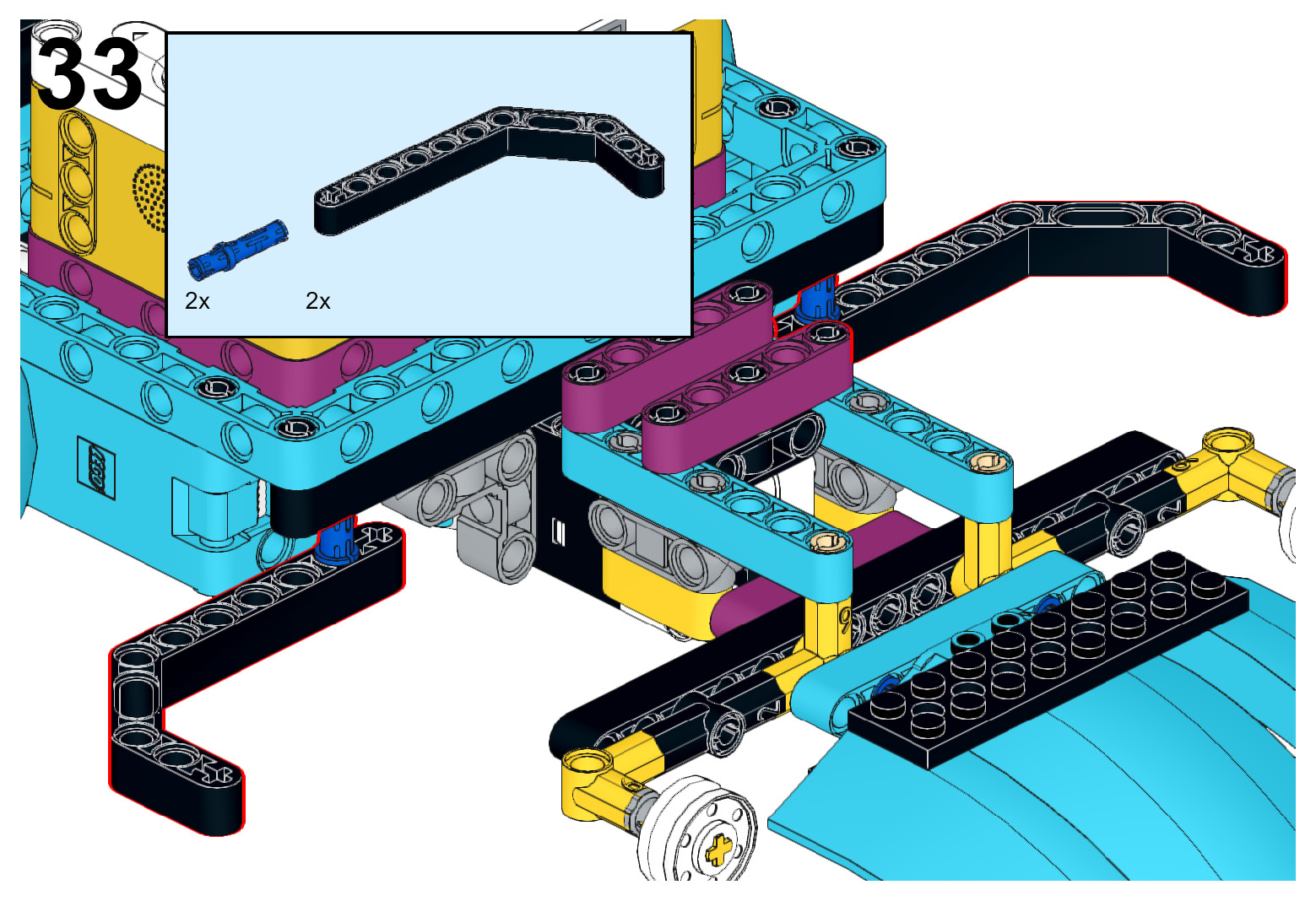
Figure 5.34 – Building roll-away attachments
- Attach an azure 2L beam with a pin and axle holes to the blue connector pin. Insert a black axle and pin connector through the axle hole of the azure 2L beam and black double-bent lift-arm beam.
Once you have done this, then attach it to each side of the robot body on the black 15L beam of the main robot frame:
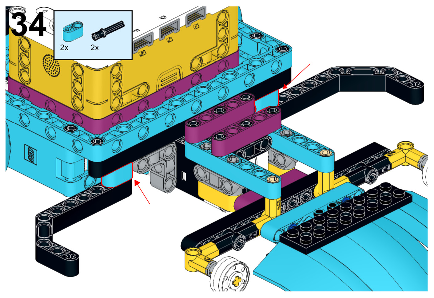
Figure 5.35 – Attaching the roll-away attachment to the robot
- At each of the black double-bent lift-arms, add a tan connector pin to the second pin hole. Attach a pulley wheel hub to the tan connector pin:
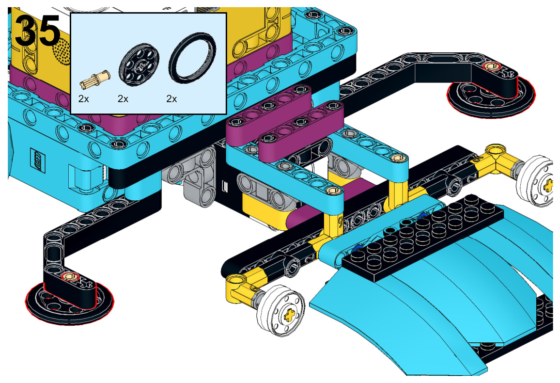
Figure 5.36 – Attaching the roll-away wheels
- The last step is to add a few elements to round out the body of the robot for looks. The steps are as follows:
A. Add two black connector pins on each side of the Intelligent Hub.
B. Insert a black 5x7 open frame to each of these sets of black connector pins.
C. Add a black connector pin to the outside edge of each of the black 5x7 open frames:
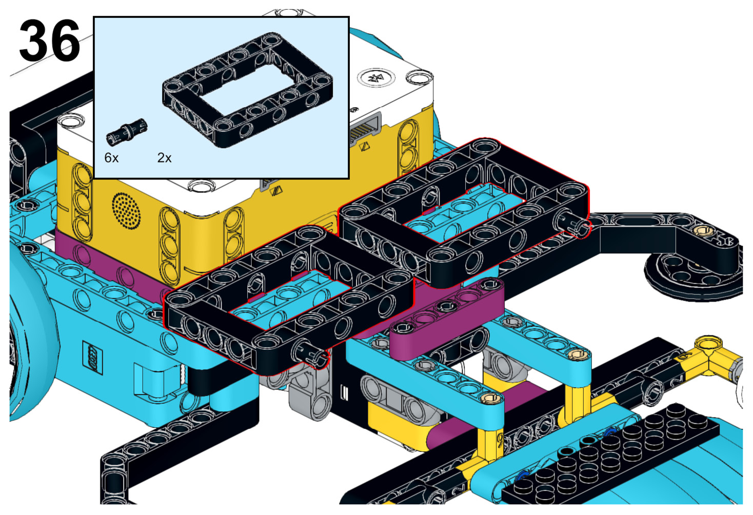
Figure 5.37 – Attaching the 5x7 open frames
- Attach an azure curved panel to the Intelligent Hub using two black connector pins. These pieces will sit on top of the black 5x7 open frames.
Add a black 15L beam across the two black 5x7 open frames. Attach another azure curved panel to this black 15L beam using two black connector pins:
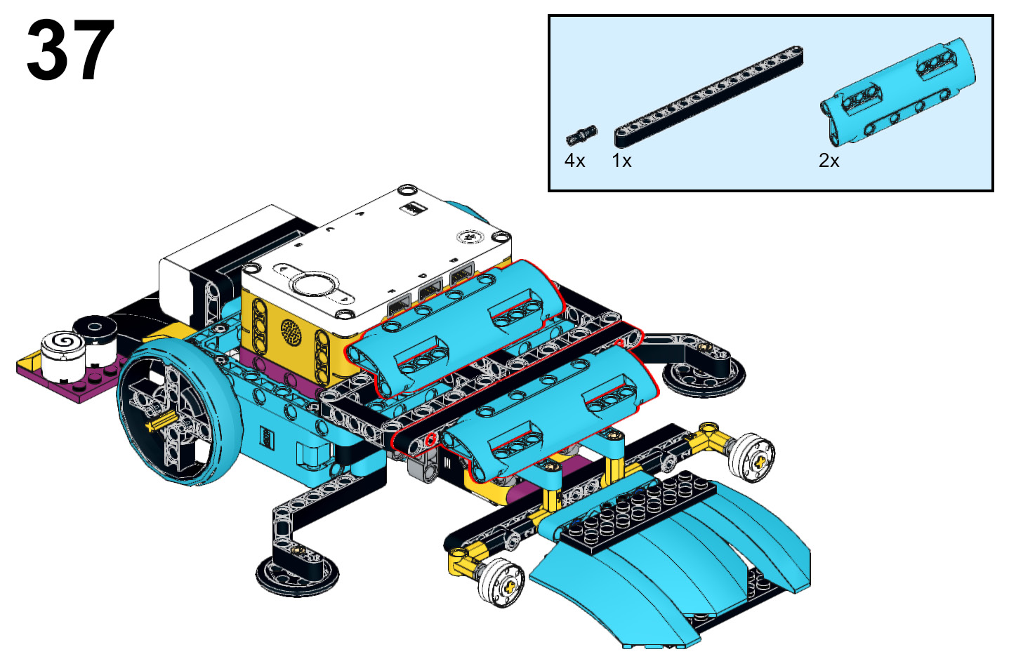
Figure 5.38 – The robot is now complete!
When it comes to organizing the wires, the key is to keep them away from the wheels and sensors. Also, it is important to have them away from the sides where another robot can get entangled in them. There is no perfect way to work the wires, but here is one way you can do it:
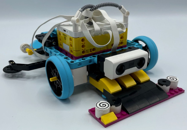
Figure 5.39 – The robot with wires on top
That's it! You have successfully built the sumobot. The fun now shifts to the coding as you design a program to keep the robot in the arena and looking to strike your opponent.
Writing the code
The code you are going to create is one where the robot will be able to do the following:
- Stay in the arena by stopping and backing up when the white rim of the arena is detected.
- Speed up to push an opponent out of the arena when the ultrasonic sensor detects an object up close.
- Speed up to push an opponent out of the arena when the force sensor detects touch from behind.
In all, there are six code stacks to make this happen. Let's begin.
The ports
You will connect the medium motors to ports C and F, the color sensor to port A, the ultrasonic sensor to port D, and the force sensor to port E:
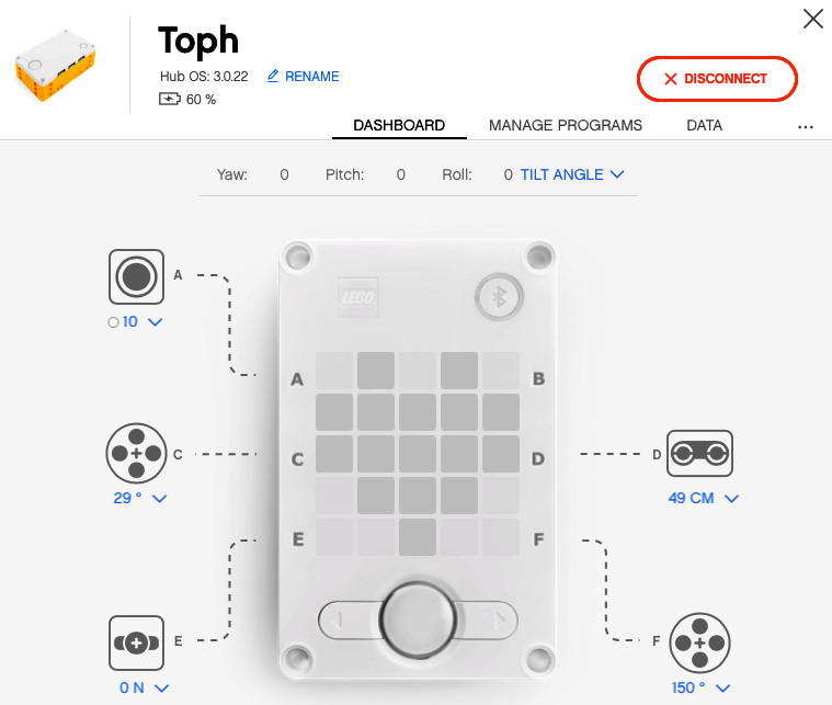
Figure 5.40 – The port view in the software
Before you code, you will need to add a More Movement extension block to your coding options. At the bottom left of your coding canvas, there is an extension block icon. Click on this icon, click on Show block extensions and select More Movement:
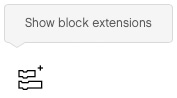
Figure 5.41 – Show block extensions
Now that your programming canvas is set up and ready, it is time to begin to build the first code stack that will activate the motors.
Code stack 1 – motors
This short code stack is just identifying which motors are for movement. It is kept open in case you want to modify and add more to it on your own. Let's begin adding the coding blocks:
- Add a yellow events block named when program starts.
- Add a pink movement block named set movement motors to and choose C and F:
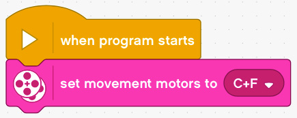
Figure 5.42 – The code stack for motor identification
Code stack 2 – end program
This code stack is designed to be able to turn off your robot when you need it to stop running. This is helpful if robots get tangled up, time expires, or you win! The steps for end program are as follows:
- Add a yellow events block named when left Button pressed.
- Add an orange control block named stop all:

Figure 5.43 – The code stack for end program
Code stack 3 – main program
This is the brains of the operation. This code stack will help the robot make decisions based on a series of events and actions. Again, this is designed in a way that you can always create your own sumobot and adjust its behaviors.
The following steps will be the main program:
- Add a yellow events block named when program starts.
- Add a purple light block named turn on for 2 seconds and change the graphic to number 3 and the time to 1 second.
- Add a purple light block named turn on for 2 seconds and change the graphic to number 2 and the time to 1 second.
- Add a purple light block named turn on for 2 seconds and change the graphic to number 1 and the time to 1 second.
- Go to the dark orange variable block section and click Make a Variable, and name it action.
- Add a dark orange variable block named set action to 0 and change it to 1:
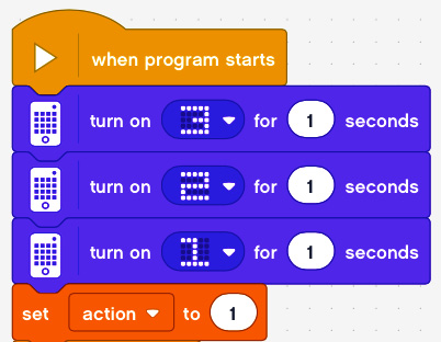
Figure 5.44 – The first five code blocks for this code stack
- Add an orange control block named forever.
- Inside the forever block, add an orange control block named if then:
A. Add a green operator block with an equal sign. Make the left side the orange variable block named action and the right side the numerator 1.
B. After the then statement, add a pink more movement block named start moving straight at 50% and change the percentage to -25%:

Figure 5.45 – Action variable when 1
- Add another orange control block named if then:
A. Add a green operator block with an equal sign. Make the left side the orange variable block named action and the right side the numerator 2.
B. Add a pink more movement block named move straight for 10 cm at 50% speed and change to 2 rotations at 75% speed.
C. Add a pink more movement block named move straight for 10 cm at 50% speed and change to a green operator block named pick random for the direction, with a range of -100 to 100 for 2 seconds at 75% speed.
D. Add a dark orange variable block named set action to and choose numerator 1:
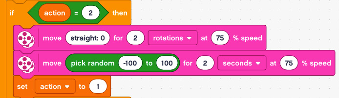
Figure 5.46 – Action variable when 2
- Add another orange control block named if then:
A. Add a green operator block with an equal sign. Make the left side the orange variable block named action and the right side the numerator 3.
B. Add a purple sound block named play sound Cat Meow until done.
C. Add a pink movement block named start moving straight at 50% and change to -75%.
D. Add an orange control block named wait until and add a blue operator block named ultrasonic D is closer than 15% and change to farther than 8 in.
E. Add a dark orange variable block named set action to and choose numerator 1:
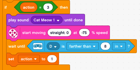
Figure 5.47 – Action variable when 3
- Add another orange control block named if then:
A. Add a green operator block with an equal sign. Make one side the orange variable block named action and the other side the numerator 4.
B. Add a pink movement block named stop moving.
C. Add a pink more movement block named move straight for 10 cm at 50% speed and change to 1 rotation at 75% speed.
D. Add a dark orange variable block named set action to and choose numerator 1:
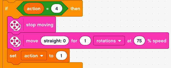
Figure 5.48 – Action variable when 4
- Add another orange control block named if then:
A. Add a green operator block with an equal sign. Make the left side the orange variable block named action and the right side the numerator 5.
B. Add a pink movement block named start moving straight at 50% and change to 75% speed.
C. Add an orange control block named wait until and add a blue force sensor block when sensor is released.
D. Add a pink movement block named stop moving.
E. Add a dark orange variable block named set action to and choose numerator 1:

Figure 5.49 – Action variable when 5
Now that you have programmed the various actions of the robots, you now need to write some code to enable these actions to occur.
Code stack 4 – white edge program
This code stack will help determine whether your robot sees the white edge and moves into action accordingly. The steps are as follows:
- Add a yellow events block named when program starts.
- Add an orange control block name forever:
A. Add an orange control block named if then:
- Change the if statement to a blue sensor block named color reflection < 50% and change to > 90%.
- Add a dark orange variable block named set action to and choose numerator 2 for the then statement:
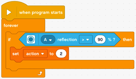
Figure 5.50 – The code stack for when the robot sees white
Your color sensor is now programmed and now you need to program the ultrasonic sensor.
Code stack 5 – ultrasonic program
This code stack will help the robot decide what to do when an object is detected. The steps are as follows:
- Add a yellow events block named when program starts.
- Add an orange control block name forever:
A. Add an orange control block named if then:
- Change the if statement to a blue sensor block named ultrasonic is closer than 15% and change to 6 inches.
- Add a dark orange variable block named set action to and choose numerator 3 for the then statement.
B. Add an orange control block named if then:
- Add a green operator block named and for the if statement.
- Change one side of the and statement to a blue sensor block named ultrasonic is closer than 15% and change to 6 inches.
- Change the other side to a blue sensor block named color reflection < 50% and change to > 90%.
- Add a dark orange variable block named set action to and choose numerator 4 for the then statement:

Figure 5.51 – The code stack for when the robot detects an object with the ultrasonic sensor
You are now down to one sensor left to program. It is time to write some code for the force sensor.
Code stack 6 – force sensor program
Just like you programmed earlier for the ultrasonic sensor, you need to write code for the force sensor to detect the impact when your robot collides with your opponent.
The following steps will code your robot to detect collisions and move into attack mode:
- Add a yellow events block named when program starts.
- Add an orange control block named forever:
A. Add an orange control block named if then:
- Change the if statement to a blue sensor block named force sensor is pressed.
- Add a dark orange variable block named set action to and choose numerator 5 for the then statement.
B. Add an orange control block named if then:
- Add a green operator block named and for the if statement.
- Change one side of the and statement to a blue sensor block named force sensor is pressed.
- Change the other side to a blue sensor block named color reflection < 50% and change to > 90%.
- Add a dark orange variable block named set action to and choose numerator 4 for the then statement:

Figure 5.52 – The code stack for when the robot detects touch with the force sensor
Your code is now complete and should look something like Figure 5.53(A) and Figure 5.53(B) when all done:
_B17864.jpg)
Figure 5.53(A) – The complete view of code
_B17864.jpg)
Figure 5.53(B) – The complete view of code
Go ahead and compete and see how your robot does. Remember, you have the power, imagination, and intelligence to make the robot better to your liking.
Making it your own
Just like every build so far, the challenge here is to take this build and code and modify it to your needs. Here are some ideas to explore if you desire:
- Implement another battle technique using the large motor.
- Gain more power by gearing your motors and wheels.
- Redesign the plow of the sensors to something else.
- Rewrite the code to have your robot behave in new ways.
- If you need help making a sumobot arena, then this website is a great place to get started: http://www.robotroom.com/SumoCircleMini.html.
- If you want to see examples of sumobot battles, then check out my EV3 camp website where you can see videos. Keep in mind these use LEGO Mindstorms EV3 as SPIKE Prime was not available in previous years: - https://sites.google.com/view/lego-ev3-camp-2019/sumobots.
- If you need a portable sumobot arena, this is one solution: https://www.youtube.com/watch?v=QeKa_r-OrK0&feature=youtu.be.
As you explore and try new methods, be sure to document and share so others can learn from your genius.
Summary
In this chapter, you explored how to build a robot that can compete in sumo competitions. You built out some attachments to coordinate with sensors so that your robot can make decisions and respond to an opponent in the field. The robot capitalized on a few standard strategies involving being low to the ground, allowing it to push an opponent by lifting them up.
Finally, we explored the coding by using code stacks to make decisions using a variable named action. This allows you to make a more precise decision-making robot.
In the next chapter, you will explore another robot that will succeed in another type of competition built for speed – the dragster!