Chapter 4: Building a Mechanical Bird
Biomimicry is the study and application of products, systems, mechanisms, and solutions to problems based on biological processes and functions found in nature. It is incredible what you can learn from plants and animals to find solutions to your own problems.
One of the many fascinating animals on our planet is the bird. It is a creature that has some features that are perfect for robot building and creating mechanisms. In this chapter, you are going to build a mechanical bird robot designed around the major features of this creature. You will be building wings and a body to look like a bird flying looking for prey.
Here is what your bird will look like by the end of this chapter:

Figure 4.1 – This is what your build will look like by the end of this chapter
In this chapter, we will break down the building and programming as follows:
- Building the body frame of the mechanical bird
- Building the wings of the mechanical bird
- Building the head and torso
- Writing the code
- Activating the bird
- Making it your own
Technical requirements
For the building of the robot, all you will need is the LEGO SPIKE Prime Kit. For programming, you will need the LEGO SPIKE Prime app/software.
Access to the code can be found here: https://github.com/PacktPublishing/Design-Innovative-Robots-with-LEGO-SPIKE-Prime/blob/main/Chapter%204%20-%20Bird.llsp.
You can find the code in action video for this chapter here: https://bit.ly/32is4IH
Let's start building it!
Building the body frame of the mechanical bird
The beauty of this robotics kit is that you can easily get started with any type of build because of the new pieces that are included. You are going to use the two yellow 11x19 base plates to create a platform for the bird to be built upon:
- Connect these two yellow base plates using two black connector pins along the long side of the base plates.

Figure 4.2 – Connecting two yellow base plates together
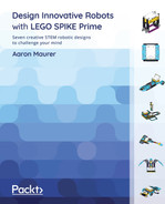
- Add two azure 11x15 open frames to each end of the base you just assembled. Use two black connector pins on each end pin hole along with one gray perpendicular four-pin element to secure each open frame in place.
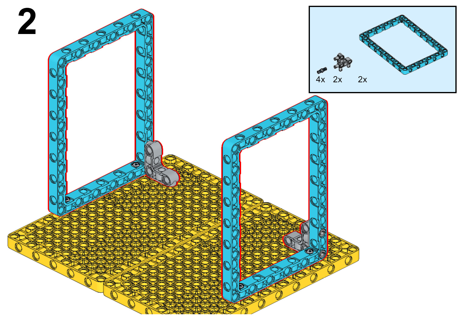
Figure 4.3 – Attaching two azure open frames to the yellow base plates
- Now that the base frame is built to keep the bird in flight, it is time to build the frame of the body of the bird. Start with the Intelligent Hub. On each side of the Intelligent Hub, secure a purple 7x11 open frame using two gray bush connector pins. Additionally, add two black connector pins to the outside edges of the open frames, as shown in Figure 4.4:
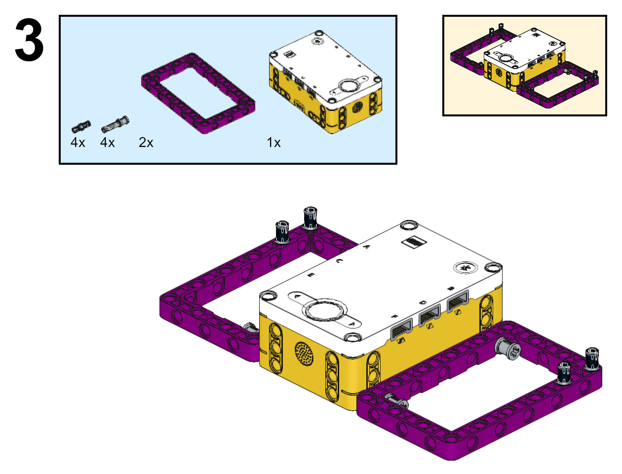
Figure 4.4 – Building the base frame of the bird's body
- Using the black connector pins, attach the bird's body frame to the azure 11x15 open frames.

Figure 4.5 – Securing the bird frame to the azure open frames
- It is now time to add some additional structural support. Starting on the outside top edge of each of the azure 7x11 open frames, attach a 3L yellow beam using one black connector pin and one blue connector pin. Following this, attach an azure 3x5 L-shaped beam securing the Intelligent Hub to the azure 7x11 open frames again using one black connector pin and one blue connector pin on each element.
Figure 4.6 – Adding structural support to the Intelligent Hub
- Add a purple 5L beam to the top of the 3L yellow beam and the 3x5 azure L-shaped beam using the blue connector pins still showing from the previous step. On top of the purple 5L beams, attach a gray perpendicular four-pin element. Finally, connect a black 5x7 open frame to each of the gray perpendicular four-pin elements.

Figure 4.7 – Adding black open frames to the top of the build
The base frame for the bird is complete. You will continue to add to the body, but for now, it is time to transition to building the wing mechanisms for movement.
Building the wings of the mechanical bird
In order to have a quality-looking bird, you need wings that move and flap just like you see in the wild. These next steps will help create the mechanism for the wings to flap:
- Inside each of the purple 7x11 open frames, insert a medium motor using two gray bush stop pins on the top and bottom of the side of each motor.

Figure 4.8 – Inserting the two medium motors
- Just like all previous builds in this book, be sure your motors are in the 0 position by aligning the gray dots on the motor gear and frame. Once you have double-checked the alignment, attach a yellow 3L beam to each of the motors using a tan axle pin and a black connector pin. Once the 3L yellow beam is attached, add another black connector pin to each of the elements on the bottom pin hole.

Figure 4.9 – Adding yellow 3L beams to medium motors
- To add the wing structures, follow these steps:
- Start by adding an azure 13L beam to the black connector pin on each of the medium motors.
- On the third pin hole from the other end on the azure 13L beam, insert a 3L pin connector with a 2L axle using the axle side with a bush stop inserted on the 2L axle side of the pin. Attach a purple 11L beam to this pin on the third pin hole.
- Add a black connector pin to the last pin hole of the azure 13L beam. Attach a purple 11L beam to the black connector pin using the end pin hole.
While the following figure shows these elements being held in place, the reality is that in this step, they will fall. You will secure them upright in the next step:
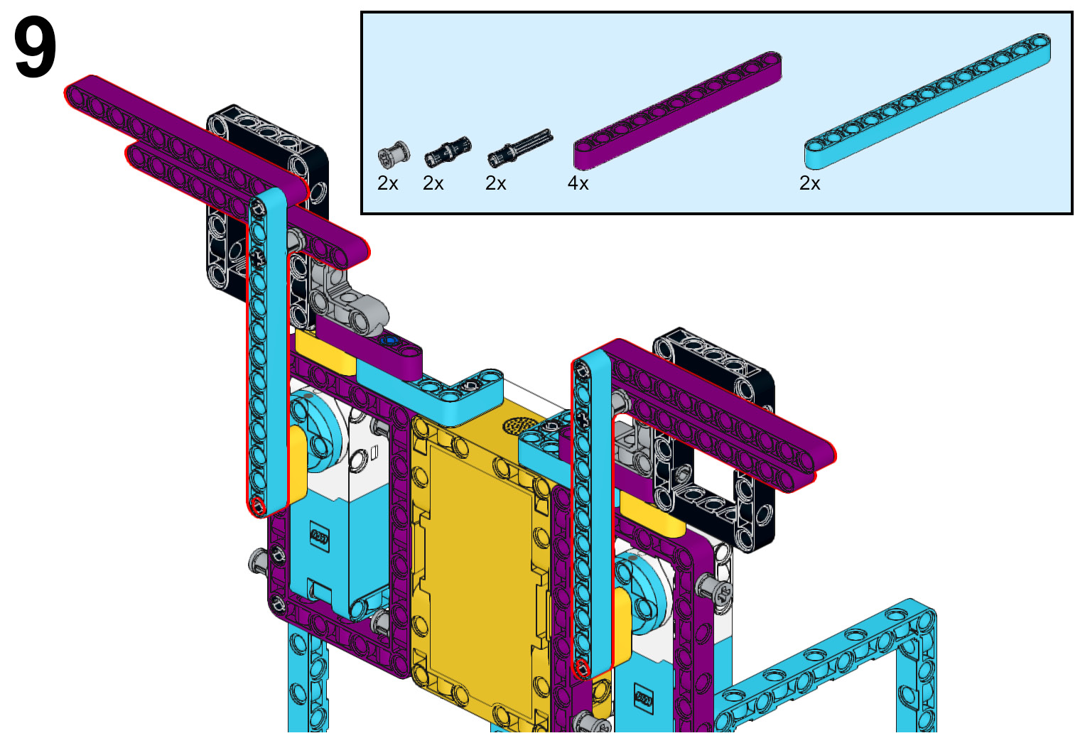
Figure 4.10 – Adding beginning wing structures
- Use a black connector pin to secure the wings upright by adding this pin to the fourth pin hole of the bottom purple 11L beam and connecting the pin to the black 5x7 open frame. Do this on both sides. On all four of the purple 11L beams, insert a 3L pin connector with a 2L axle on each end with the axle side facing toward the front.
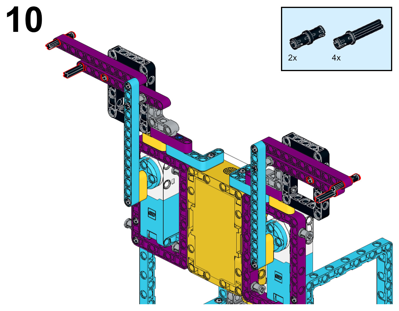
Figure 4.11 – Adding pins to extend the wings
- You are going to continue to build out the wings in this next step. To begin, attach a blue connector pin to an azure 13L beam. Leave the 2L part of the blue connector out. Insert this azure 13L beam on the black connector pin at the top end of the purple beam on the bird. Secure it in place using a yellow 2x4 L beam connected to the blue connector pin and black connector pin. Do this for both wings.

Figure 4.12 – Extending the wings
- The steps to add the wings are as follows:
A. Attach three black connector pins to the azure 13L beam and attach an azure 11x3 curved panel to this beam.
B. Connect an azure 7L beam to the top of the 11x3 curved panel using a black connector pin. Be sure to leave two pin holes hanging over the end of the curved panel.
C. Snap an azure 8x3x2 wedge to the end and secure it using the two pin holes of the 7L beam.
Do this for both wings:

Figure 4.13 – Adding the ends of the wings
It is now time to begin working on the head and torso of the bird's build.
Building the head and torso
With the wings now ready, let's continue to build the body to cover up some of the wing mechanisms and bring the bird to life:
- To begin this next section, attach the large motor to the top of the Intelligent Hub using four black connector pins. This motor will be used to rotate the head of the bird.
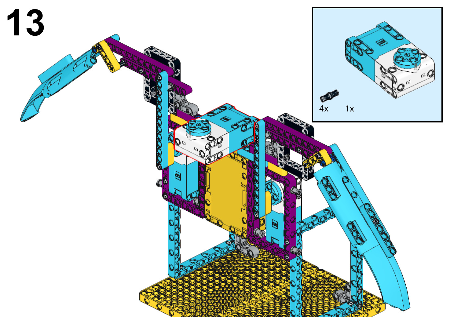
Figure 4.14 – Attaching the large motor to the Intelligent Hub
- On the underside of the large motor, insert a gray 5L axle beam on the motor.

Figure 4.15 – Inserting an axle beam on the large motor
- You are now going to build a submodel that will be used to build out the legs of the bird. Begin this submodel by inserting a tan connector pin on a yellow axle and pin connector #6. In Figure 4.16, you will see what the submodel will look like when complete in the upper right-hand corner:

Figure 4.16 – Inserting a tan connector pin onto the yellow axle and pin connector
- Stack two white axle and pin connector elements using two yellow 3L axle beams. Connect these elements to the tan connector pin from the previous step into the bottom pin hole of the stack.

Figure 4.17 – Combining the white connector pin elements with the tan connector pin
- On the underside of the yellow 3L axle beams, insert a gray axle and pin connector #1. On the outside pin holes of the gray axle and pin connector #1, insert a black connector pin with a tow ball.

Figure 4.18 – Adding gray connector pin #1 and a black connector pin with a tow ball
- Attach this submodel to the gray 5L axle beam connected to the large motor using the yellow axle and pin connector #6.

Figure 4.19 – Attaching the submodel to the large motor
- It is now time to add the legs to the bird. You will be building another submodel. Begin by using two purple 2x4 bricks. Insert a red axle pin connector to each of them along with a white axle and pin connector #4.
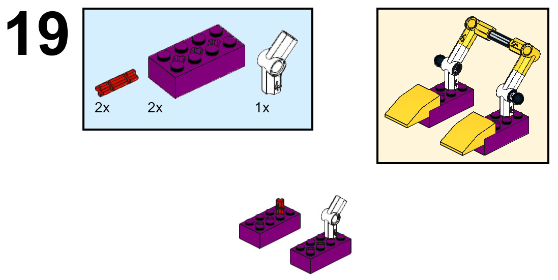
Figure 4.20 – Building the bird's feet
- Insert a red axle connector pin on the top of each of the white axle and pin connectors #4. Attach a yellow axle and pin connector #6 to the top of each red connector pin. Secure them together using a black 4L axle beam.

Figure 4.21 – Connecting the legs together
- The last step of this submodel is to attach a yellow curved 3x2 slope to the end of each of the 2x4 purple bricks. Insert a black connector pin with a tow ball to each of the pin holes on the white axle and pin connector #4.
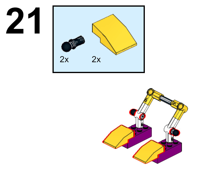
Figure 4.22 – Completing the legs
- The legs are going to be added under the large motor and the submodel you built in previous steps. The following figure gives you a view of where it will be placed. At this point, the legs are not connected to the bird frame:
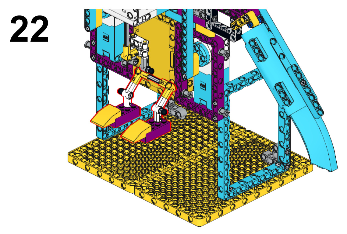
Figure 4.23 – Location of the submodel
- Now that you have an idea of where the legs will be placed, you will connect them to the bird's torso using two black 1x6 link elements.
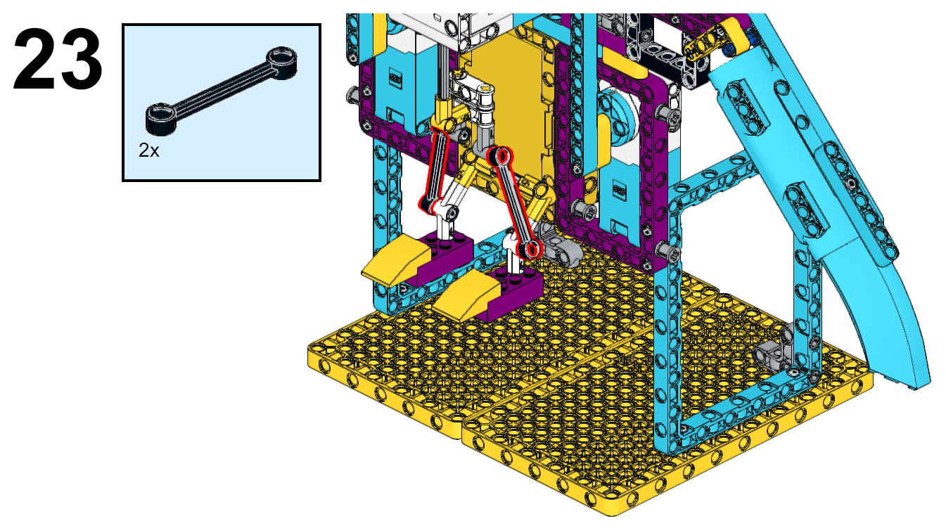
Figure 4.24 – Connecting the feet to the torso
- Let's move to the head build now that the legs are complete. To begin, attach a black double bent beam to each side of the large motor using two black connector pins for each double bent beam.
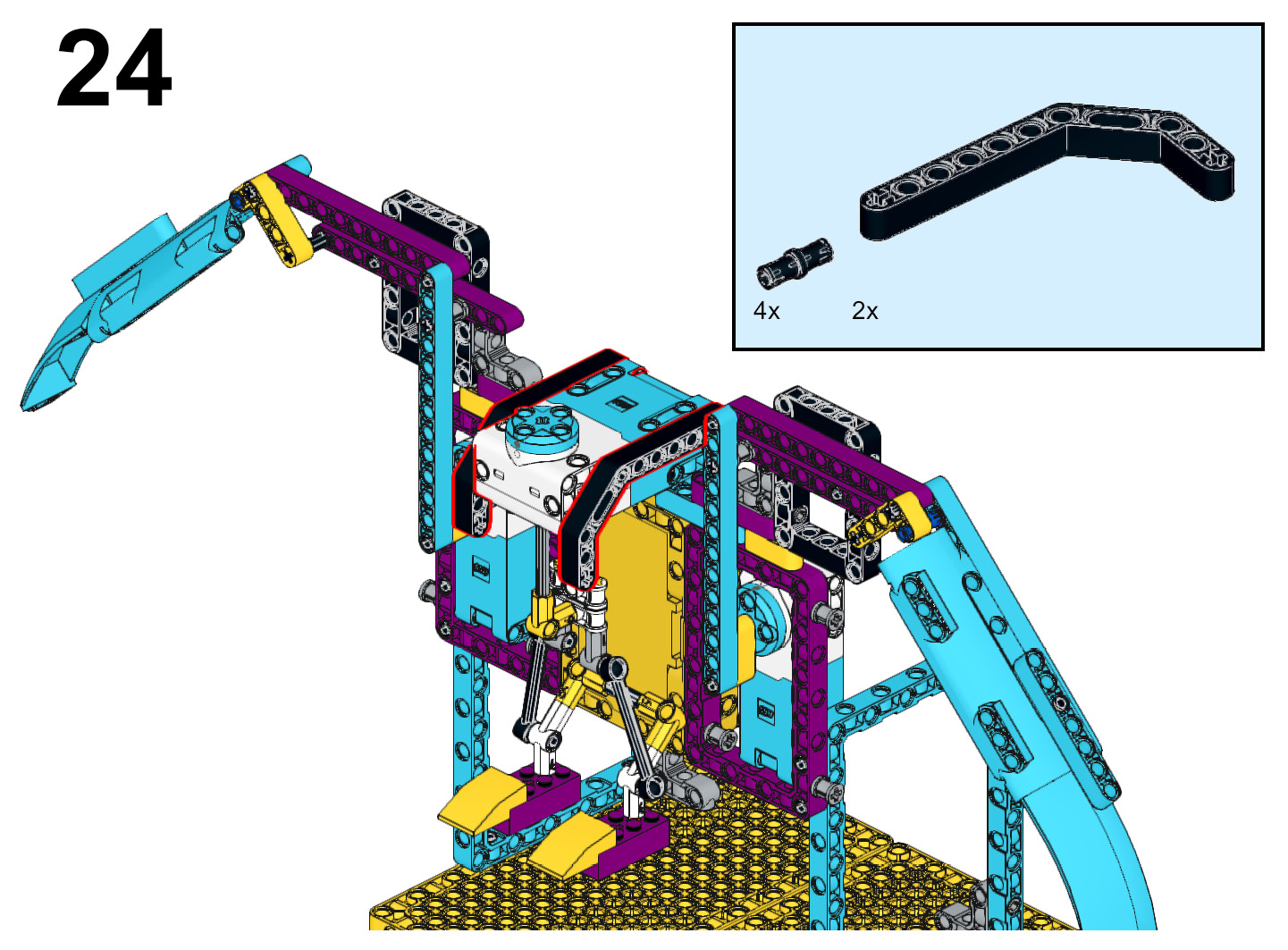
Figure 4.25 – Attaching black liftarms to the sides of the large motor
- Connect a black 9L beam to each of the black double bent beams using a black connector pin and a tan connector pin on each double bent beam.

Figure 4.26 – Attaching a black 9L beam to the black double bent beam
- When facing the front of the bird, insert two black connector pins seven pin holes apart. Insert the black connector pins in the third and sixth pin holes from the top of the black 9L beam. Slide an azure 7L beam onto the two black connector pins. Add two blue connector pins to each end of the azure 7L beam.

Figure 4.27 – Attaching the azure 7L beam to the black 9L beam
- Slide two more azure 7L beams onto the blue connector pins. Secure these three azure 7L beams to the other black 9L beam using two black connector pins.
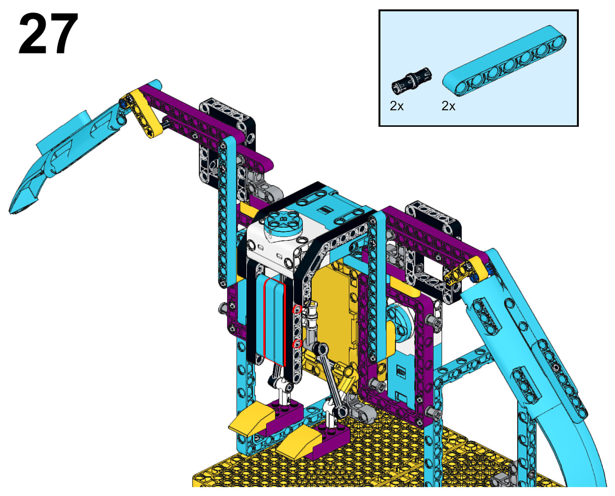
Figure 4.28 – Completing the body of the bird
- To build the base for the beak and the head, follow these steps:
A. On top of the large motor, begin by adding two blue connector pins.
B. Insert a black 2x8 plate onto each of the blue connector pins.
C. Secure these plates together using a black round tile piece.
D. Insert a black biscuit element on the top of the blue connector pins vertically, as shown in the following figure.
E. Add two black connector pins to the black biscuit element.

Figure 4.29 – Building the base for the beak and head
- Insert two black 2x8 plates onto the black connector pins on the black biscuit element.
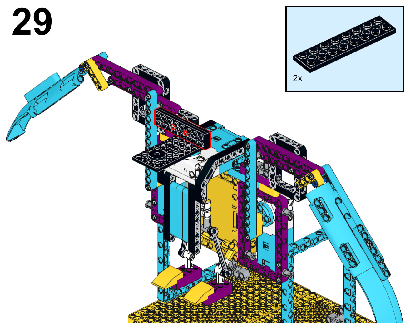
Figure 4.30 – Attaching two black 2x8 plates to the black biscuit element
- Using the pin holes on the back of the ultrasonic sensor, add a black connector to each and secure them onto the black 2x8 plates.
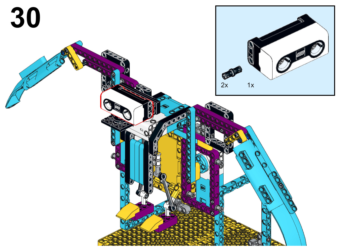
Figure 4.31 – Attaching the ultrasonic sensor
- Here are the steps to build out the beak of the bird:
A. Add a yellow curved 3x2 slope to the end of each of the black 2x8 plates. Hold them together by adding a yellow 2x4 brick to the underside.
B. Add two black connector pins to the top of the black biscuit element.
C. Attach a black 6x2 slope to each of the black connector pins.
D. Attach an azure 8x6x2 windscreen element to the top of the black 6x2 slope.

Figure 4.32 – Building out the head of the bird
- Add two gray perpendicular pin connectors to the top purple beam on each wing. Insert a purple biscuit element on each of the gray perpendicular pin connectors.

Figure 4.33 – Adding structure to the wings
- This next set of steps will help with the look of the wings in the join areas:
A. Add two black connector pins to the inside purple biscuit element on each wing.
B. Attach a tire to these black connector pins.
C. Insert a red axle connector pin on the middle of each wheel.
D. Attach an azure 2x2 round plate to the red axle connector pin.
E. Attach a white spiral tile to the top of each azure 2x2 round plate.
F. Insert a black connector pin on pin holes four and six on the azure 13L beam that is connected to each medium motor.
G. Attach a black biscuit element to these connector pins.
H. Attach two more black connector pins to the bottom of each of the black biscuit elements.
I. Attach a black 3x11x1 panel plate to these black connector pins.

Figure 4.34 – Final decoration elements
Your bird is now complete. It is now time to write some code to bring the bird to life.
Writing the code
The code for the mechanical bird will use the ultrasonic sensor as both the eyes and to trigger movement. The goal is to mimic a bird in flight looking for prey, so we will work to ensure the legs move with the head gesture as well as the wing mechanics.
The ports
You will connect the ultrasonic sensor into port B. You will plug the large motor into port F. You will plug the two medium motors into ports C and D.

Figure 4.35 – Port view in the software
Calibrating the motors
This first code stack will make sure that the head and wing motors are all set to position 0 before being activated to ensure everything works smoothly and properly:
- Under the when program starts block, insert a purple light up block that activates the lights on ultrasonic sensor B lighting up to 0 0.
- Add a pink movement block named set movement speed to and make it 15%.
- Add a blue set speed to motor block, set it to 10%, and change it to motor F.
- Add three blue go shortest path to position 0 motor blocks. Change them to motors C, D, and F.

Figure 4.36 – Calibration of the motors code stack
Wing movement
You will create a new code stack to allow the wings to move when triggered by an object in view of less than 5 inches:
- Add a yellow event block for the ultrasonic sensor that reads when closer than. Change it to port B and the distance to 5 inches.
- Add a pink movement block named set movement motors to and set it to C+D.
- Add another pink movement block named move for 10 cm. Change the setting to 5 rotations.
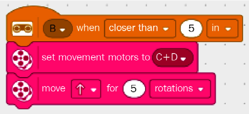
Figure 4.37 – Code stack for wing movement
Eyes and head movement
The final code stack will give the eyes the appearance of blinking, along with the head moving to scan for food:
- Add a yellow event block for the ultrasonic sensor that reads when closer than. Change it to port B and the distance to 5 inches.
- Add an orange control block named wait and change it to .5 seconds.
- Add an orange control block named repeat until:
A. In the space of this block, add a green operator block of equal comparison.
B. On the left side of the comparison, insert a blue motor block with C power.
C. On the right side of the comparison, type in a value of 0.
- Within the repeat until block, do the following:
A. Add a purple light block for the ultrasonic sensor named light up and turn on all the lights.
B. Add a blue motor block named go shortest path to position for motor F and change it to 330.
C. Add an orange control block named wait and change it to .5 seconds.
D. Add a blue motor block named go shortest path to position for motor F and change it to 30.
E. Add a purple light block for the ultrasonic sensor named light up and turn off all the lights.
F. Add an orange control block named wait and change it to .25 seconds.

Figure 4.38 – Code stack for the eyes and head movement
Here is a look at the code altogether:
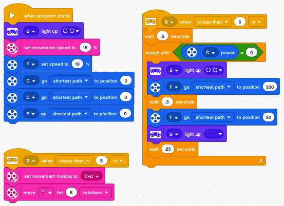
Figure 4.39 – Final look of the code
You have done it! Congratulations. Turn on the code and your bird and watch it come to life. Remember, this is just the start of the possibilities. What will you do to make it your own?
Activating the bird
This is just short sample code to get your bird started. You can continuously tinker with your code, changing various settings in the code as well as on the bird to get the bird working the way you choose.
While tinkering, here are some things I tried and found that I liked:
- Adjust the pins of the blue beams connected to the medium motors for different wing angles and movements.
- Adjust how the eyes blink, changing the light patterns.
Remember, the beauty of imagination and creativity is taking new learning and transforming it into whatever you desire. Let's explore some other ideas to spark your imagination.
Making it your own
Just like every build, the challenge here is to take this build and code and modify it to your needs. Here are some ideas to explore if you desire:
- Program the LED on the Intelligent Hub to mimic feather movement.
- Use the force sensor to trigger another behavior.
- Add sound effects.
- Build a model of food that can be clutched in the talons of the bird.
It is now up to you to transform your bird into the creature of your imagination. The possibilities are endless!
Summary
In summary, we explored how to make a mechanism powered by a motor to give the movement of wings of a bird in flight. You explored some new build techniques by using some of the basic elements that are found in the kit to help give a more realistic movement of the legs moving with the head while flying.
Finally, we explored the coding by using code stacks to make decisions. The eyes and head move if the power of motor C is not at 0. Once this motor stops, so do the head and eyes.
In the next chapter, you will explore building another robot by having a go at perhaps the most popular build idea – the sumobot.