Motors are devices that use electrical power to create mechanical rotation. With a LEGO motor, an axle can be inserted in the motor to make use of the revolution to, for example, spin the wheels of a robot or vehicle. But the motors have extra functionality: as servo motors, they are capable of precisely moving to a specific angle using a sensor inside the motor that monitors its angle and speed. The Hub uses the sensor embedded into the motor to allow setting the angular position of the motor’s rotation or set the motor’s speed. The exercises and project in this chapter show how to take advantage of the Robot Inventor motor’s capability for powering wheels, precise angular movement, and rotation sensing.
Speed and Angle

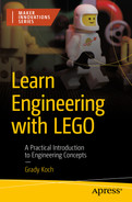
A photo of a machine that has 2 parts and four holes on the top. There is a point in the middle. It is the indicator of zero position.
The motor’s zero position indicator
Exercise: The Speed and Angle Demonstrator

A photo exhibits a hub with a motor attached to the side. The motor is connected to the hub through a port. A toy LEGO character is at the bottom.
The Speed and Angle Demonstrator

Two 3-D illustrations of a hub and connecting pin arrangement. It indicates the number of pins as 2 and number of hubs as 1.

A 3-D illustration of a hub and motor connection. It indicates the motor is attached to the hub and connected to a port through the wire.

A 3-D illustration of a hub and motor connection. There are 2 additional connecting pins attached to the motor. It indicates the number of pins as 2 at the top.

A 3-D illustration of a hub and motor connection along with an extended liftarm. It indicates the motor is connected to the port F of the hub.
Although the Robot Inventor measures motor speed as a value out of 100, or a percent of the maximum speed, another common way to describe motor speed is by revolutions per minute (RPM). RPM is an indicator of how many times the motor completes a full rotation over a time span of one minute. For example, the Medium Motor that comes in the Robot Inventor set has a maximum RPM of 135, so a 100 percent speed setting in a program corresponds to an RPM of 135.
Controlling Motor Speed in Word Blocks

A screenshot of a word blocks code, that has 6 steps from start to exit, as follows. 1. start. 2. set speed. 3. spin. 4. delay. 5. spin. 6. stop.
Setting motor speed in Word Blocks
Step 2: The set speed to block assigns a speed setting to the motor. Any following blocks that operate a motor will use this setting. Without this block, a motor will use a default speed of 75 percent.
Step 3: The run for block turns on the motor with user selection for the port to which the motor is connected, direction of rotation, and duration. The motor will run at the speed set in step 2.
Step 4: The wait block pauses the spinning of the motor. This pause keeps the motor from jerky motion before the next motor command of step 5.
Controlling Motor Speed in Python
The code begins by importing modules and creating a myhub object, as in all the Python code in this book. Next, an object is created to represent the motor 1. Motor() is a module within the mindstorms package imported in the first line of code, and to enable use it’s given a variable name: motor. The Hub’s port, on which the motor is connected, is specified inside the parentheses of Motor()—in this case, port F. Now the functions associated with the motor can be conveniently used, as seen in the next few lines of the program.
A motor can be turned on at a constant speed with the motor object’s run_for_seconds() function 2. This function runs the motor for the duration in seconds that are specified as the first number in parentheses, five seconds in this case. The second number in parentheses is the speed setting, set to 100 here for maximum speed. The speed setting can also be negative, which means that the rotation will be counterclockwise. After a one-second pause, a counterclockwise spin comes next 3.
Setting Motor Angle in Word Blocks
While the previous section described setting speed, the other basic parameter to work with is setting the motor’s angle position. An option for setting the angle is the direction for going to the specified angle: clockwise, counterclockwise, or in the shortest direction. For the shortest direction selection, the motor chooses whichever direction is the quickest to reach its destination.

A screenshot of a word blocks code, that has 10 steps from start to exit. The initial speed is set to 50%. The spinning position moves through 90, 0, 270, and 0.
Setting motor angle in Word Blocks
Step 3: The go to position block sets the motor’s angle to the position specified. Other input parameters include the port that the motor is connected to and the direction in which the motor should rotate as it travels to the specified position. The motor will move at the speed set in step 2. This block is used again in steps 5, 7, and 9 to position the motor at various angle settings.
Step 4: The wait block pauses action in the program to let the angle dwell at a position specified in the previous block. Such a wait block is also used in steps 6 and 8 to also pause at new motor settings.
Setting Motor Angle in Python
The motor’s run_to_position() function 2 is used repeatedly in the program to set various angle settings. This function takes three parameters in parentheses. The first is the angle to which the motor should rotate. The second parameter is the direction of the rotation: ‘clockwise’, ‘counterclockwise’, or ‘shortest path’. The third parameter is the speed of the rotation to the specified angle. A dwell time at each angle setting is made by pausing action with the wait_for_seconds().
Exercise: Understanding Torque and Stall
Motors have a limit to the amount of force, called torque, that they can spin with. If a task is to move something heavy with a motor, then a powerful motor is needed to apply high torque. Chapter 4 introduced the idea of torque, showing that gears need a certain amount of torque to get a gear system moving. In the experiments of Chapter 4, torque was supplied turning a crank. Instead of the crank, a motor can be attached to a gear system or machine to apply torque using electrical power. But there’s a limit on how much torque a motor can supply.

A photograph of a motor with a lift arm, a torque lift arm, and an angle demonstrator. A LEGO character stands at the bottom.
A liftarm is added to the Speed and Angle Demonstrator to block rotation of the motor

An illustration of a hub and motor arrangement along with other parts. 4 small connecting pins are attached to the hub.

A 3-D illustration represents the arrangement of a hub, motor, and an extended attachment of a liftarm.
With the liftarm now installed to the Speed and Angle Demonstrator, running the program for setting motor speed will show that the motor jams up against the blocking liftarm. This situation of the motor becoming stuck is called stall. After a pause, the motor will spin around in the opposite direction to again stall against the liftarm. Whichever direction the motor goes, it can’t push off the blocking liftarm because there isn’t enough torque to do so.
This exercise also shows that each time the motor stalls against the blocking liftarm, the motor will push for about two seconds, then back off and stop trying to push. This automatic shutoff is a safety feature built into the motor to prevent the motor, or whatever object is being pushed on, from being damaged. This safety feature can be shut off with advanced programming, but it’s best to keep the automatic stall shutoff until more is learned about using motors.
The Robot Inventor set comes with Medium Motors, but LEGO also makes a higher torque motor called the Large Motor that works with the Hub—the same programming Word Blocks or Python functions can be used for either motor. The Large Motor has 2.3 times higher torque than the Medium Motor.
Exercise: Powering a Vehicle with a Tank Drive

A photograph exhibits a tank made by the arrangement of the hub, motor, and connectors. A toy LEGO character is at the bottom.
The Tank uses a pair of motors that each drive a wheel
Building the Tank
Three wheels are involved with the Tank, with two large wheels driven by motors and a third wheel to give balance to the Tank. Without the third wheel, the Tank would fall over. This balancing wheel is a design called a caster, which has the ability to pivot to align with the direction of the Tank’s travel. Casters can be seen in action in everyday life on shopping carts and desk office chairs. A LEGO caster is part of the Tank building instructions, at steps 13–18.

A 3-D illustration represents the front and back view of the hub. 6 connecting pins are attached to the back of the hub connector.

A 3-D illustration represents the arrangement of a hub and motor. The motor is connected to the hub by wires.

A 3-D illustration represents the arrangement of a hub and motor. It indicates the motors are at the bottom and connections are at the back side of the hub.

A 3-D illustration represents the arrangement of a hub and motor. There is an attachment of an additional connector that comprises 9 holes in a row.

A 3-D illustration represents the arrangement of a hub and motor. 4 connecting pins are attached to the additional connector at the front.

A 3-D illustration represents the arrangement of a hub and motor. 2 smaller connectors and 1 wider connector are attached through the connecting pins.

A 3-D illustration represents the hub and motor arrangement. There are 3 small and 2 large connecting pins attached to the connectors at the front.

A 3-D illustration represents the hub and motor arrangement. it indicates the attachment of a connector with 9 holes facing upward.

A 3-D illustration represents the hub and motor arrangement. it indicates the attachment of 3 connecting pins at the front facing upward.

A 3-D illustration represents the hub and motor arrangement. it indicates the attachment of a connector through the connecting pins.

A 3-D illustration represents the hub and motor arrangement. it indicates the attachment of a connecting pin near the left motor.

A 3-D illustration represents 2 wheels attached to the motors present on either side of the hub. The wheels are connected to each side of the motor through connecting pins.

An illustration of assembled pieces of a motor. it indicates the mechanism between the connecting pins and the connectors.

An illustration of assembled pieces of the connectors. it indicates 2 head parts and 2 body parts of the connecting pins and their assembly in the connector.

An illustration of assembled pieces of the connectors. It has 2 parts. Each part is depicted separately.

An illustration of assembled pieces of the connectors. It has 2 parts. Each part is depicted separately.

An illustration of assembled pieces of the connectors. It indicates the connecting pins connectors separately.

A 3-D illustration represents 2 wheels attached to the motors present on either side of the hub. It highlights the assembly of multiple pieces of connectors at the front.

A 3-D illustration represents the hub and motor arrangement. The wheels are attached to the side. It indicates the attachment of 2 connecting pins at the top of the hub.

A 3-D illustration represents the hub and motor arrangement with wheels attached to the side. The wires from the motors are connected to the port of the hub. It indicates passing the cable through the wire connector and connecting the end of the cable to ports b and f.
Programming the Tank
Spin the Tank clockwise for five seconds, then move forward for two seconds, and backward for two seconds. Finally, spin counterclockwise for five seconds. Between each maneuver, pause for one second.
- 1.
Start the program.
- 2.
Assign motors to port B for the left motor and port F for the right motor.
- 3.
Spin clockwise for five seconds.
- 4.
Delay for one second.
- 5.
Move forward for two seconds.
- 6.
Delay for one second.
- 7.
Move backward for two seconds.
- 8.
Delay for one second.
- 9.
Spin counterclockwise for five seconds.
- 10.
Stop the program.

A flow diagram presents 10 steps as follows. 1. start. 2. assign ports. 3. spin clockwise. 4. delay 1 s. 5. move forward. 6. delay 1 s. 7. move backward. 8. delay. 9. spin counterclockwise. 10. stop.
Flowchart for the Tank algorithm
The Word Blocks Code

A screenshot represents the Word Blocks code to drive the tank. It has 10 steps. 1. start. 2. assign ports. 3. spin clockwise. 4. delay. 5. move forward. 6. delay. 7. move backward. 8. delay. 9. spin counterclockwise. 10. stop.
Word Blocks code to drive the Tank
Step 2: The set movement motors to assigns the ports to which the motors are attached. The left motor is on port B, and the right motor is on port F.
Step 3: The move for block turns on both motors. This block includes options for distance, time, and angular degree, with the time option used here. Another option is for selection of the direction of the tank as indicated by an arrow, allowing selection for straight movement or spins. A clockwise spin is selected in this step, whereas blocks 5, 7, and 9 use different directions.
The Python Code
An object is created to represent both motors with the MotorPair() function 1, which comes from a module within the mindstorms package. The port assignment is made in parentheses, with the left motor listed first. Control of the tank drive is then made with the move_tank() function by passing it the length of time, units of seconds, left motor speed, and right motor speed in parentheses 2. For example, to make the Tank spin, both motors are given the same speed but in opposite directions. While the 'seconds' unit is used here, other possible units for this function include distance, rotations, and degrees. The end of each maneuver by the Tank is marked by pausing with a wait_for_seconds() function.
Exercise: Using a Motor As a Rotation Sensor

A photograph of the hub and motor arrangement that has a lift arm in front attached to the motor. A geared wheel is attached to the other motor on the left side. A LEGO character is at the top of the hub.
The Position Mimic keeps a liftarm pointed in the same direction as the indicator on a control knob
Building the Position Mimic
The Position Mimic uses two motors, one as a control knob and one as a pointer that orients a liftarm. The knob motor, on the left side, serves to measure the angle position of the knob. The pointer motor, on the right side, points in the same angle as the knob motor. The control knob uses a gear to allow getting a good grip when turning the knob, and an indicator attached in front of the gear on the control knob shows the angle position that the motor holding the liftarm should duplicate.

A 3-D illustration represents a rectangular base. It has holes on its surface. 4 connecting pins are attached to the base facing upward.

A 3-D illustration represents the hub attached to the rectangular base through the connecting pins.

A 3-D illustration represents the hub attached to the rectangular base through the connecting pins. 8 connecting pins are attached to the base with 2 pairs at either end and 4 in the middle.

A 3-D illustration represents the hub attached to the rectangular base. 2 motors are attached to the base facing toward the front. The motors are connected to the hub through wires.

A 3-D illustration represents a hub attached to the rectangular base along with 2 motors connected with it. It indicates 2 connecting pins on the right motor and 1 long pin on the left motor.

A 3-D illustration represents a hub attached to the rectangular base along with 2 motors connected with it. A geared wheel is attached to the left motor, while a Liftarm is attached to the right motor.

A 3-D illustration represents a hub attached to the rectangular base along with 2 motors connected with it. It indicates the left motor is connected to port b and the right motor is connected to port F of the hub.
Programming the Position Mimic
Make the pointer motor continuously set its angle to the same angle as the knob motor. Keep up the angular tracking until either the left or right button on the Hub is pressed to stop the program.
- 1.
Start the program.
- 2.
Create a loop that repeats unless the left or right button is pressed. If either button is pressed, skip to step 4.
- 3.
Set the angle position of the pointer motor to be the same as the knob motor.
- 4.
Stop the program.

A flow diagram depicts 4 steps as follows. 1. start 2. Repeat if the button is not pressed. 3. Move the pointer motor. 4. stop.
Flowchart for the Position Mimic algorithm
The Word Blocks Code

A screenshot represents the word blocks code. It includes 4 steps that comprise, start, repeat, move, and stop.
Word Blocks code for the Position Mimic algorithm
Step 2: The repeat until block sets up a loop that repeats indefinitely until the condition is met that either the left or right button is pressed on the front. This means of stopping the program was also used in Chapter 2 for the Dance Floor.
Step 3: The go to position block tells the pointer motor to go to the angle position that matches the position measured on the knob motor. In other words, this block both reads a motor (the knob motor on port B) and rotates a motor (the pointer motor on port F).
The Python Code
The two motors are each assigned as objects 1, 2. A while True loop is used to keep the program running indefinitely 3, unless a button is pressed on the Hub 4. This loop-until-button-pressed design was also used in Chapter 2 for the Dance Floor. Within the loop, two lines of code measure the knob motor’s angle position and match this angle on the pointer motor. The knob’s measured position is taken with the get_position() function and assigned the value to a variable named position 5. This variable then gets inserted in the run_to_position() function, which makes the pointer motor go to the same angle as the knob motor 6. The run_to_position() function takes two additional parameters: the direction, set to ‘shortest path’, and the motor speed. Full speed can make the pointer motor’s motion jittery, so the speed is decreased to a level of 75.
Project: The Rear-Wheel Drive Car

A photograph of a car model made by the arrangement of hub, motor, connectors, and wheel. A LEGO toy character is at the bottom.
The Rear-Wheel Drive Car
Building the Rear-Wheel Drive Car
Instructions to build the Rear-Wheel Drive Car are given as follows. The drive wheels, at the rear of the car, use the differential described in Chapter 5 to make smooth turns. The motors should be zeroed before their installation, as in Figure 6-1. This is especially important for the steering motor, because the direction the car will steer is referenced to the motor’s zero position. In other words, the motor’s zero position has the car steered to go straight.

A 3-D illustration represents a motor with connecting wires. It exhibits 3 connecting pins attached to the motor on its backside.

A 3-D illustration represents a motor with connecting wires. It exhibits a rectangular connector attached to the back of the motor through the connecting pins.

A 3-D illustration represents a rectangular connector attached to the back of the motor. It denotes 2 smaller pins attached to the side, while 1 larger pin is attached at the top of the connector.

A 3-D illustration represents a rectangular connector attached to the back of the motor with a connecting pit at the top. A large rectangular connector is attached to the side of the smaller connector through 2 connecting pins. The middle portion of the larger connector is blank.

A 3-D illustration represents a rectangular connector attached to the back of the motor. A large rectangular connector is attached to the side of the smaller connector. It denotes that 8 connecting pins are fixed to the large rectangular connector.

A 3-D illustration represents a large rectangular connector attached to the back of the motor through other connectors. It denotes 4 more connecting pins fixed at its front and backside.

A 3-D illustration represents a large rectangular connector attached to the back of the motor through other connectors. 2 Liftarms and 2 small rectangular connectors are attached to the larger connector.

A 3-D illustration represents an assembled piece of a motor with multiple connectors. It indicates the application of 6 connecting pins on either side of the motor.

A 3-D illustration represents an assembled piece of a motor with multiple connectors. It indicates the application of 2 Liftarms on the side of the motor through the connecting pins.

A 3-D illustration represents an assembled piece of a motor with multiple connectors. It denotes the application of 2 more Liftarms perpendicular to the motor on either side.

A 3-D illustration represents an assembled piece of a motor with multiple connectors. It denotes 2 smaller and 2 larger connecting pins fixed on the vertical Liftarms.

A 3-D illustration represents an assembled piece of a motor with multiple connectors. It denotes the application of 2 more connectors on the vertical Liftarms through the connecting pins.

A 3-D illustration represents an assembled piece of a motor with multiple connectors. It denotes the application of 2 smaller and 2 larger connectors on the side.

A 3-D illustration represents an assembled piece of a motor with multiple connectors. It denotes the application of 2 smaller lift arms through the applied connectors.

A 3-D illustration represents an assembled piece of a motor with multiple connectors. It indicates 2 connectors are fixed on the extended Liftarms, on either side.

A 3-D illustration represents an assembled piece of a motor with multiple connectors. It indicates the application of 2 connecting pins horizontally, facing in the opposite direction.

A 3-D illustration represents an assembled piece of a motor with multiple connectors. 2 parts are depicted separately. It denotes the application of the 2 connecting pins on the Liftarm that has 9 holes in it.

A 3-D illustration represents a Liftarm with 9 holes on the surface. It denotes the application of 2 smaller connectors on the third and seventh holes.

A 3-D illustration represents a Liftarm with 9 holes on the surface. It denotes the application of 2 smaller connectors on the third and seventh holes. 2 connecting pins are applied on the smaller connectors in a perpendicular position.

A 3-D illustration represents a rectangular connector with connecting spaces on its border. The middle portion is blank. A Liftarm is connected at the top along with 2 smaller connectors in a horizontal manner.

A 3-D illustration represents a rectangular connector with connecting spaces on its border. These spaces help to attach different parts. It denotes the application of 2 connecting pins on the extended Liftarm attached to the rectangular connector.

A 3-D illustration of a motor assembled with the connectors. It has cables at the bottom. It has different parts on the upper surface.

A 3-D illustration represents an assembled piece of a motor with multiple connectors. It denotes the application of 2 smaller and 1 larger connecting pins on the extended Liftarm attached at the back of the motor.

A 3-D illustration represents an assembled piece of a motor with multiple connectors. It denotes the application of 3 connectors on the extended Liftarm attached at the back of the motor.

A 3-D illustration represents an assembled piece of a motor with multiple connectors. It denotes the application of 3 connecting pins to the attached connectors on the Liftarm facing downward.

A 3-D illustration represents an assembled piece of a motor with multiple connectors. It denotes the application of a Liftarm with 9 holes on it, fixed in a parallel position to the other Liftarm.

A 3-D illustration represents an assembled piece of a motor with multiple connectors. It has a long connecting wire in the back. It denotes the application of 4 connecting pins on the edge of the motor.

A 3-D illustration represents an assembled piece of a motor with multiple connectors. It has a long connecting wire in the back. it denotes the application of 2 small rectangular connectors on the side.

A 3-D illustration represents an assembled piece of a motor with multiple connectors. It indicates the application of 4 connecting pins at the backside connector, facing upward.

A 3-D illustration represents an assembled piece of a motor with multiple connectors. It denotes the application of 2 cylindrical pins indicating a text that reads also insert 2 pins on the other side of the car at the same location.

A 3-D illustration represents the backside of an assembled piece of a motor with multiple connectors. It indicates the application of 2 L-shaped connectors at the backside.

A 3-D illustration represents an assembled piece of a motor with multiple connectors. It indicates the application of 8 different parts to the assembly. It indicates to first press axles together. Second, press the pins into place.

A 3-D illustration represents an assembled piece of a motor with multiple connectors. It indicates the application of 2 wheels on either side with the help of 6 different connecting pins and a gear arrangement.

A 3-D illustration represents an assembled piece of a motor with multiple connectors along with 4 wheels at the bottom. It denotes the application of 2 wheels at the front with the help of connecting pins.

A 3-D illustration represents an assembled piece of a motor with multiple connectors along with 4 wheels at the bottom. It denotes the connection of a hub to the assembly.

A 3-D illustration represents an assembled piece of a motor and hub with multiple connectors along with 4 wheels at the bottom. It denotes the insertion of 3 pins on the left side of the car at the matching locations. It denotes the total number of pins as 6 at the top.

A 3-D illustration represents an assembled piece of a motor and hub with multiple connectors along with 4 wheels at the bottom. It denotes the application of an L-shaped Liftarms to the 3 pins on the left side of the car.

A 3-D illustration represents an assembled piece of a motor and hub with multiple connectors along with 4 wheels at the bottom. It denotes the application of 2 connecting pins on the top of the hub.

A 3-D illustration represents an assembled piece of a motor and hub with multiple connectors along with 4 wheels at the bottom. It indicates 2 instructions that read, Press the steering motor cable through the clip and connect the end of the left cable to port B and the right cable to port A of the hub.
Programming the Rear-Wheel Drive Car
Drive the car forward along a straight line for two seconds, then backward for two seconds. Repeat this motion but on a curve to the right, then repeat again for a curve to the left.
- 1.
Start the program.
- 2.
Align the steering motor for straight ahead.
- 3.
Drive forward for two seconds.
- 4.
Drive backward for two seconds.
- 5.
Align the steering motor for right curve.
- 6.
Drive forward for two seconds.
- 7.
Drive backward for two seconds.
- 8.
Align the steering motor for left curve.
- 9.
Drive forward for two seconds.
- 10.
Drive backward for two seconds.
- 11.
Stop the program.

A flow diagram depicts 11 steps. 1. start. 2. steer forward. 3. drive forward. 4. drive backward. 5. steer right. 6. drive forward. 7. drive backward. 8. steer left. 9. drive forward. 10. drive backward. 11. stop.
Flowchart for the Rear-Wheel Drive Car algorithm
The Word Blocks Code

A screenshot of the Word Blocks code denotes 11 steps. 1. start. 2. align the wheel. 3. drive counterclockwise. 4. drive clockwise. 5. align the wheel. 6. drive counterclockwise. 7. drive clockwise. 8. align the wheel. 9. drive counterclockwise. 10. drive clockwise. 11. stop.
Word Blocks code for the Rear-Wheel Drive Car
Step 2: The go to position block sets the steering motor to the zero position to align the wheels straight ahead. This block points out a couple things to double-check after building the car: the motor is zeroed and that the steering motor is connected to port B. Steps 5 and 8 also use this block, with different angle settings to steer right and left.
Step 3: The run for block turns on the drive motor to move the car, in this case for a duration of two seconds. The counterclockwise direction setting will drive the car forward, while a clockwise setting (used in step 4) will drive the car backward. This forward and backward combination is repeated again in steps 6, 7, 9, and 10.
The Python Code
There are two motors involved in the Rear-Wheel Drive Car, so objects are created for each and assigned to the variables drive and steer 1, 2. The motors’ variable names indicate their functions, making the code easier to understand. The drive motor is connected to port A, and the steering motor is connected to port B.
To steer the car, the steering motor is set to a specific angle setting using the run.to.position() 3. There are three motor parameters to enter in this function: angle setting, direction of rotation, and speed of rotation. The program uses this function repeatedly; the first time it is used, the car is steered straight ahead, so set to 0 degrees. To keep the motor from spinning to a point of being blocked as the tilted wheel hits up against the car’s chassis, the 'shortest path' parameter is used. Finally, using the full speed of the motor may cause the front end of the car to jerk, so a moderate 50 percent speed is a good choice.
Now that the steering direction is set, the next two lines of code drive the car forward and then backward with the run_for_seconds() function 4. This function takes two parameters: duration and motor speed. The direction of travel is specified with either a positive or negative motor speed. A forward direction for the car corresponds to a negative speed setting; hence, -75 percent for speed moves the car forward. Using a negative speed setting to move forward may seem counterintuitive. It’s because the vehicle’s many gears affect the direction in which the motor will direct the vehicle; the wheels in this design actually spin in the opposite direction than the motor. If a farther distance is desired, then speed can be increased to 100 percent or time duration can be increased. To move backward, a positive value for the speed should be used, in this case 75 percent.
The Rear-Wheel Drive Car can be turned by adjusting the angle of the steering motor, such as by the run_to_position() function to set an angle of 15 degrees 5. This angle tilts the car’s front wheels toward the right. To curve to the left, this function can be used again with an angle setting of 345 degrees. The angles of steering used here are examples that can, of course, be experimented with. Also, variables could be used, such as for steering angles or durations of time to drive, to allow convenient change of these parameters in more complex programs.
Summary
This chapter explored the use of the motors that come in the Robot Inventor set. A motor can be used for both simple functions, like spinning a wheel, and complex functions, like moving to a precise angle position. Several exercises worked with motors to use these spinning and positioning functions. A motor can also be used as a rotation sensor, and another exercise used this feature to make a control knob. One of the primary uses for motors is to move a wheeled vehicle or robot, and this chapter showed two ways to build a drivetrain: (1) tank drive with side-by-side motors each powering a wheel or (2) rear-wheel drive with one motor for spinning wheels and a second motor for steering. An exercise worked with tank drive, and the chapter summary project worked with rear-wheel drive.